Some video clips from the week..
Using the test equipment in the lab to observe the operation of a microcontroller circuit board
We have already used multimeter last week. We learned other instruments used for testing electronic devices in Fablab.
1. Multimeter
As per the dictionary, the multimeter is 'an instrument designed to measure electric current, voltage, and usually resistance, typically over several ranges of value'.
2. Digital Storage Oscilloscope (EZ Digital DS-1100 100MHz)
Wikipedia: Oscilloscopes are used to observe the change of an electrical signal over time, such that voltage and time describe a shape which is continuously graphed against a calibrated scale. The observed waveform can be analyzed for such properties as amplitude, frequency, rise time, time interval, distortion and others.... A digital storage oscilloscope (often abbreviated DSO) is an oscilloscope which stores and analyses the signal digitally rather than using analog techniques. It is now the most common type of oscilloscope in use because of the advanced trigger, storage, display and measurement features which it typically provides.
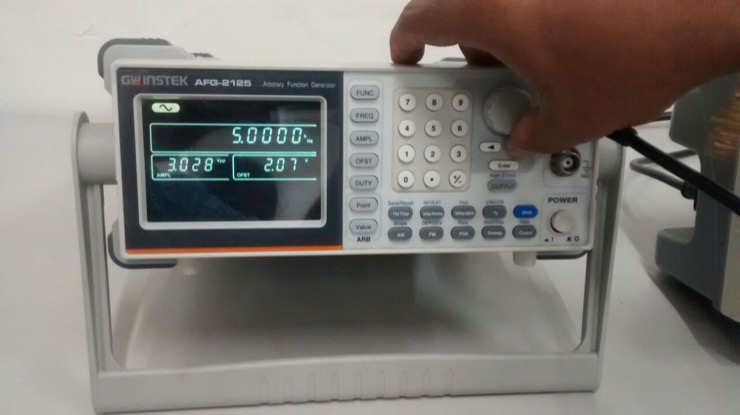
3. Function Generator (25MHZ AFG 2125)
Wikipedia: A function generator is usually a piece of electronic test equipment or software used to generate different types of electrical waveforms over a wide range of frequencies. Some of the most common waveforms produced by the function generator are the sine wave , square wave, triangular wave and sawtooth shapes.
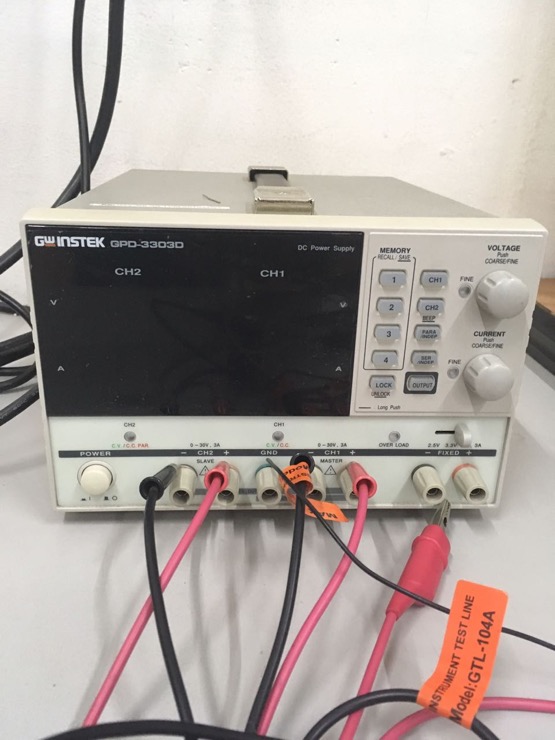
4. PowerSupply (Instek GPD-3303D)
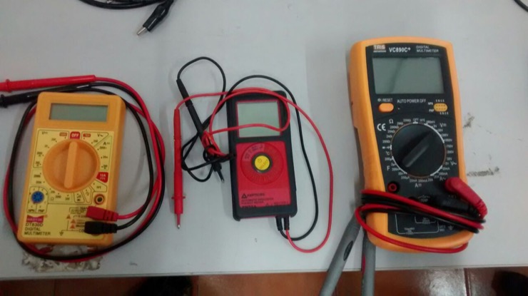
These are the different multimeters available in our lab.
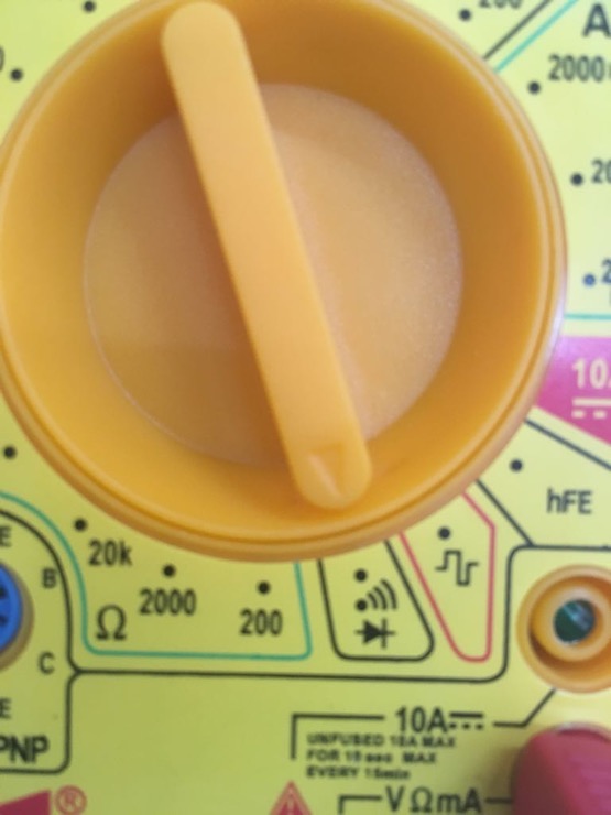
To test the circuit conductivity, turn the dial of the multimeter to 'Continuity test mode'.
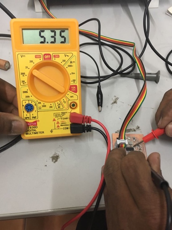
In the 'DC voltage mode', the dial is placed at 20V to test the voltage across ATTiny44. The value is around 5V.
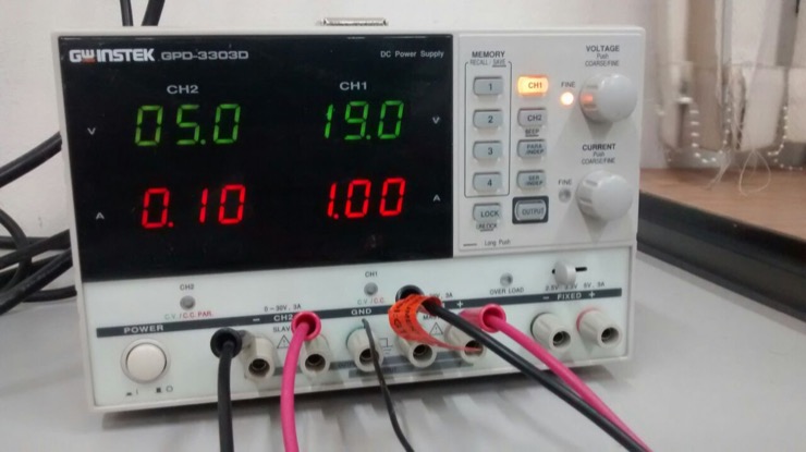
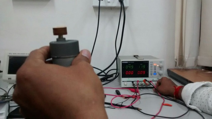
The DC PowerSupply (Instek GPD-3303D) instrument which has dual channel, with a maximum of 3A output per channel, in the voltage range of 0 to 30 V.There are buttons to choose the required channel and a knob to adjust the voltage value. The text in green refers to the voltage value and the text in red refers to the current value in ampere.There are four memory modes to store values for easy retrieval.
Press the 'Output' button, which then lights up in blue when active, to get the desired output in the channel. If the chosen values are overloading the connected device, a red LED light blinks as a warning. This is a DC motor being tested. More the load on the motor, more power is drawn.
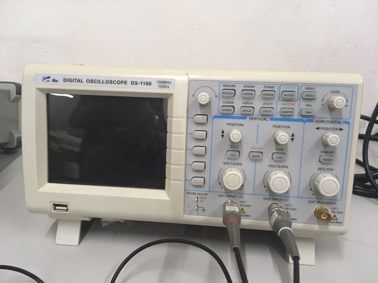
The 'Digital Storage Oscilloscope (EZ Digital DS-1100 100MHz)'in our lab. Options are available to detect AC or DC signal. Two ports are available to connect two channels, with CAT II cables.
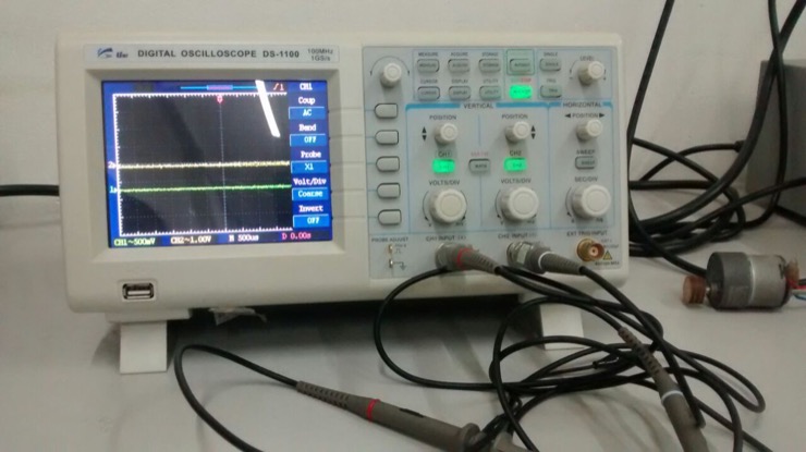
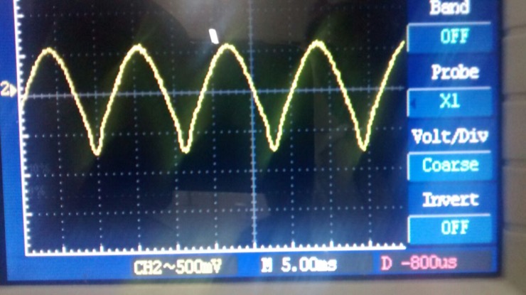
The green line refers to the signal in channel 1 and the yellow line refers to channel 2.
A test probe can be plugged in to check if the oscilloscope is detecting the signal accurately.
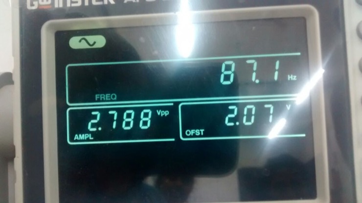
The Function Generator (25MHZ AFG 2125) in our lab.
The frequency, voltage and offset voltage of the signal to be generated can be adjusted by pressing the appropriate button and then using the knob.
A maximum of 5V signal can be generated.
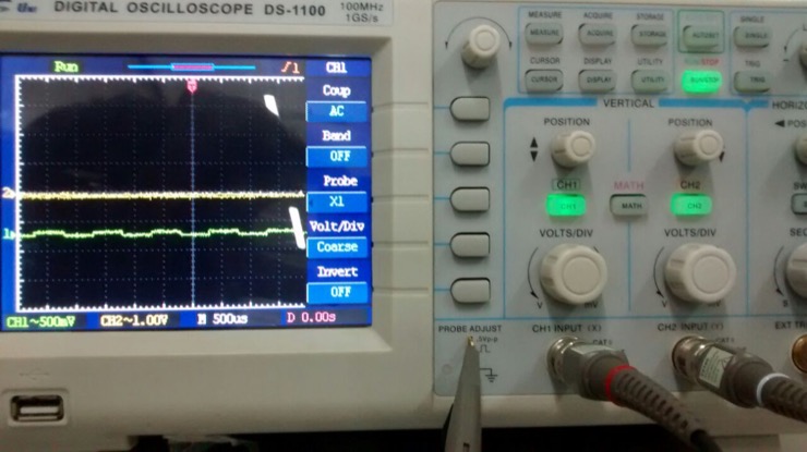
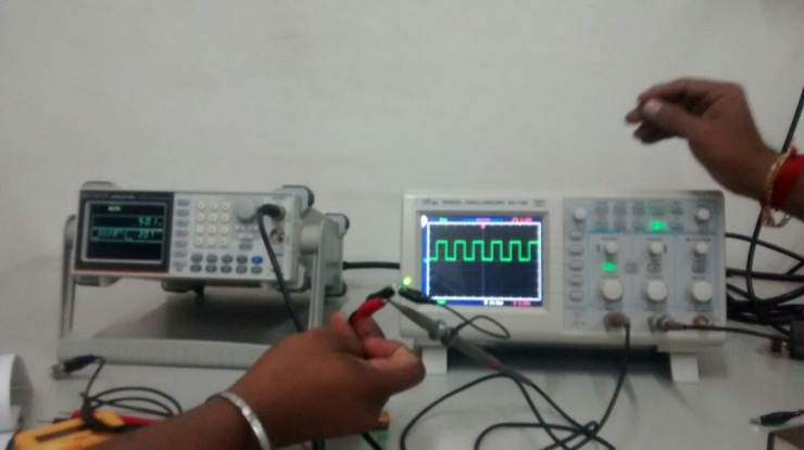
We tested an LED light by generating input signal from the Function generator. We also connected the probes of the oscilloscope to the LED to check the signal and compare if it is the same as what we generated.
The oscilloscope detected the signal nearly accurately. 2.6 (amplitude)*0.005 (5 millisecond)=0.13 ; Frequency=1/time = 1/0.13 = 7.69 Hz. This is close to the 8 Hz signal that we generated using the function generator.
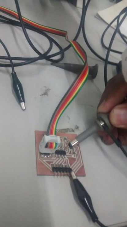
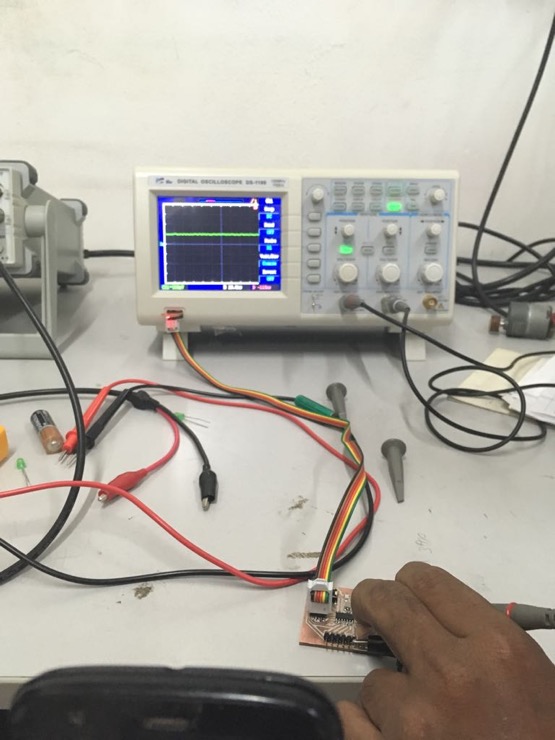
We connected one of our PCBs to a power source and analyzed the signal using the oscilloscope. The negative terminal was held to 'Ground' and the positive terminal was held to 'Vcc' in the board.
The signal was detected accurately as 5V. (10*0.5)
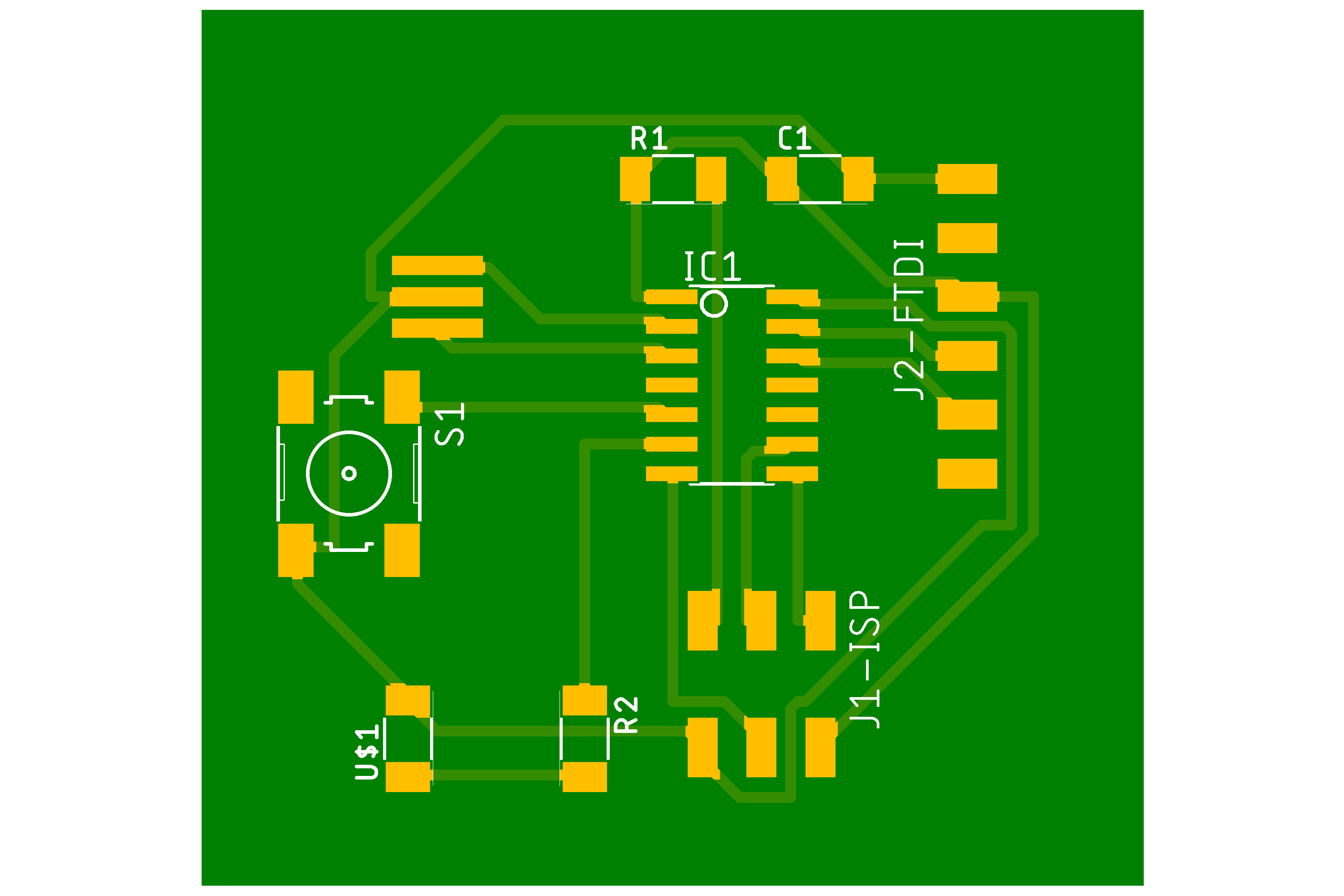
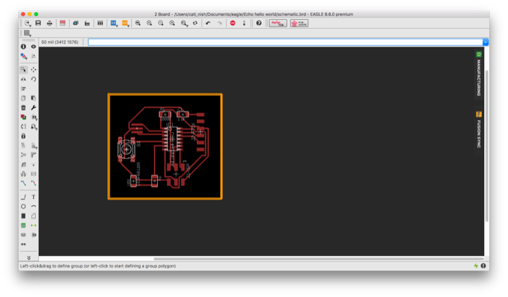
Redraw and modify the echo hello-world board. Check the design rules.
I installed
Autodesk's Eagle on my Mac to redraw the
echo hello-world board and then modify it by adding an LED, resistor and switch. I modified the design rules to mill the PCB as required and generated the files for traces and outline.
Download the design files of
traces and
outline.
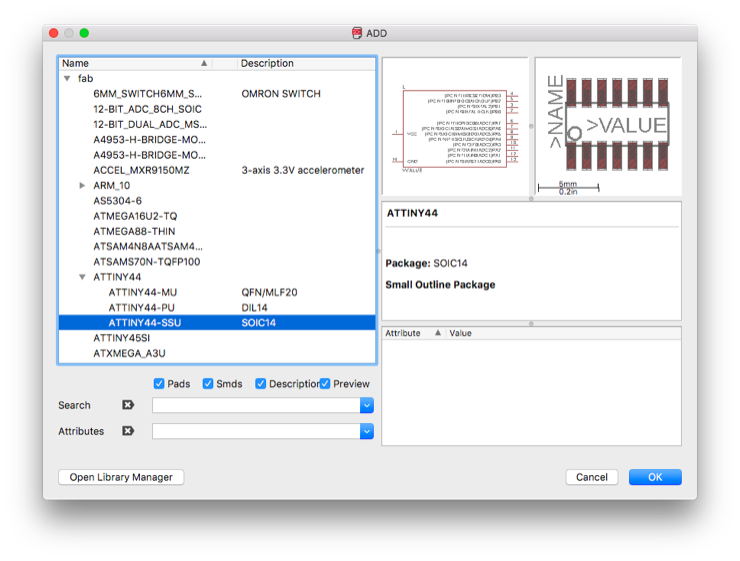
I added the fab.lbr to Eagle's list of libraries of components. I could now search and choose the components that I needed for the board from here. When there were more than one of the same kind, I always chose the one with the keyword 'fab' in its name.
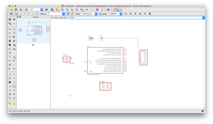
I typed 'net' in the command line to add the connections between the components.
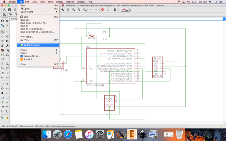
Choose 'File>Switch to board' to see the board layout.
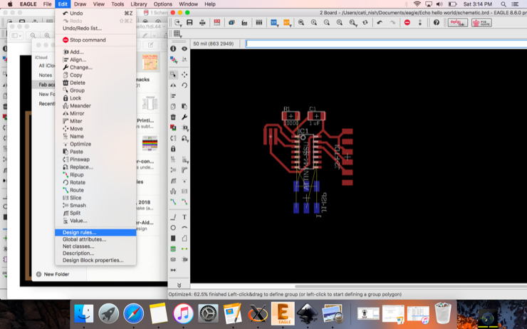
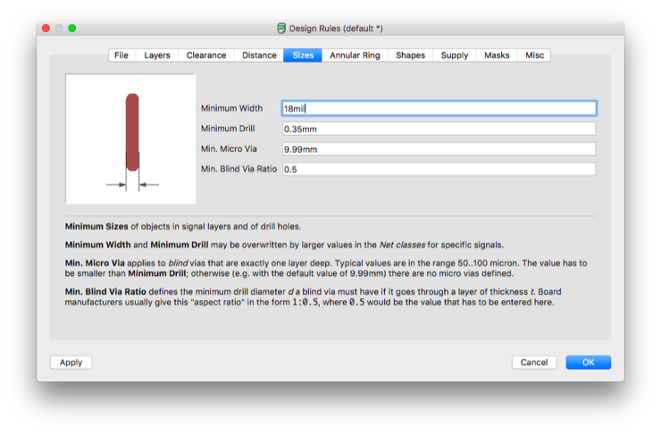
Adjust the positions of the components. Choose 'Edit>Design rules'.
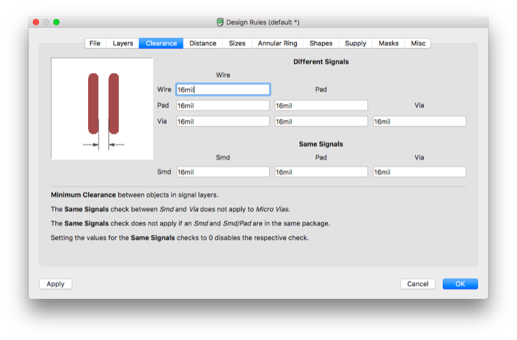
Modify the clearance which is the gap between two traces by the milling machine, to 16mil (16 millionths of an inch) which is 1/64 inch or 0.4mm. This is to accommodate the 1/64 inch tool.
The minimum width of components is chosen to be 18mil.
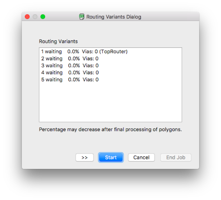
Choose Options>Autorouter ; Choose only the top layer and press 'Start'. When the job is complete, you can toggle between the different routing variants and choose the best one.
I had forgotten to add the extra components and modify the board. I switched back to schematic and added LED, resistor and switch.
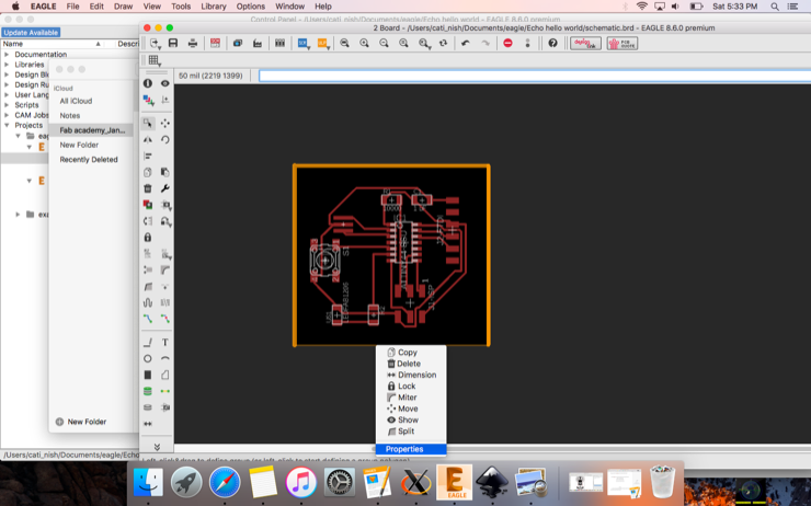
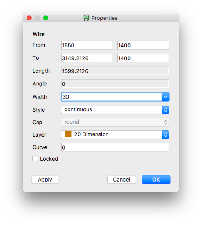
Click and drag the boundary lines to border the board. Right click on each line and choose 'Properties'.
Modify width to '30mil' to accomodate the 1/32 inch tool.
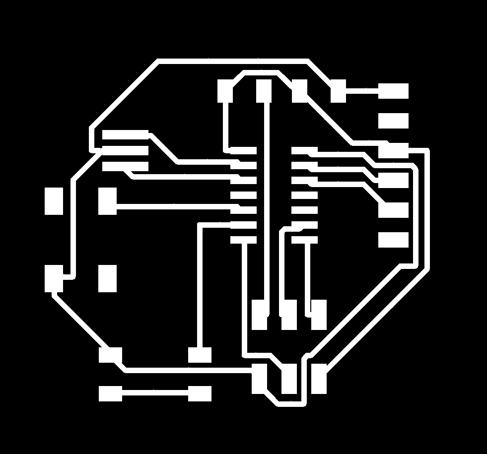
For traces, choose the top layer only in the 'layer settings'; choose background as black and image as white. For outline, choose 'Dimensions' only , choose background as white and outline in black. Export these two settings as two different image .png files.
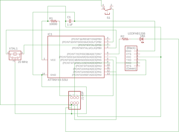
Schematic which I referred to while soldering the components on the board.
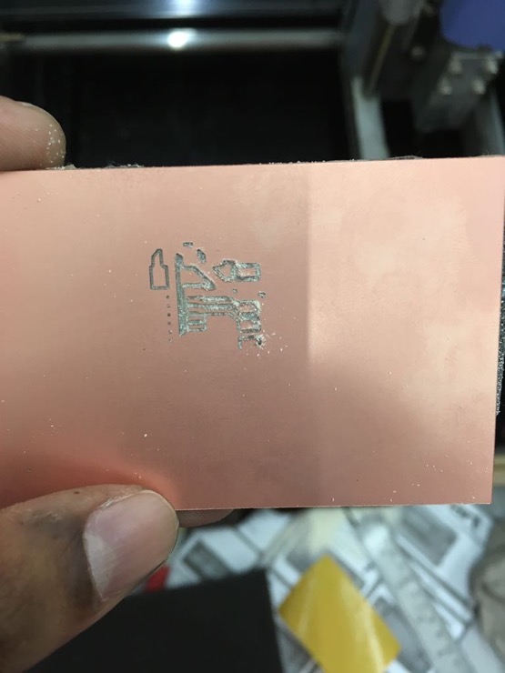
Making the PCB: milling and soldering components
I had to use the machine twice because of a partly-finished first job.
My soldering technique is still amateurish and I had to desolder and solder back a few times to get it right. I tend to pour too much lead on the board.
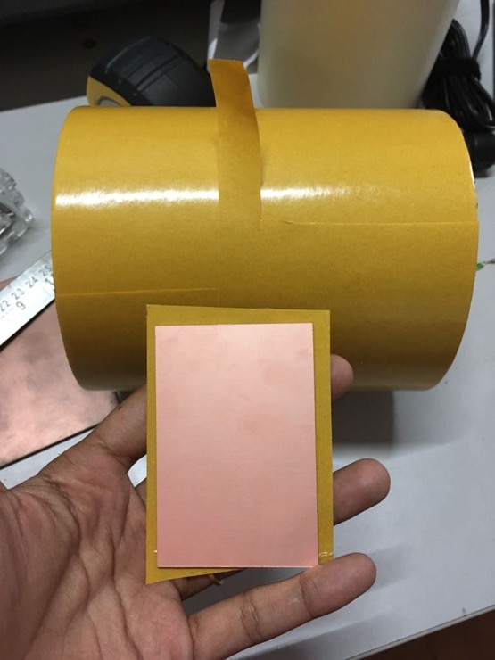
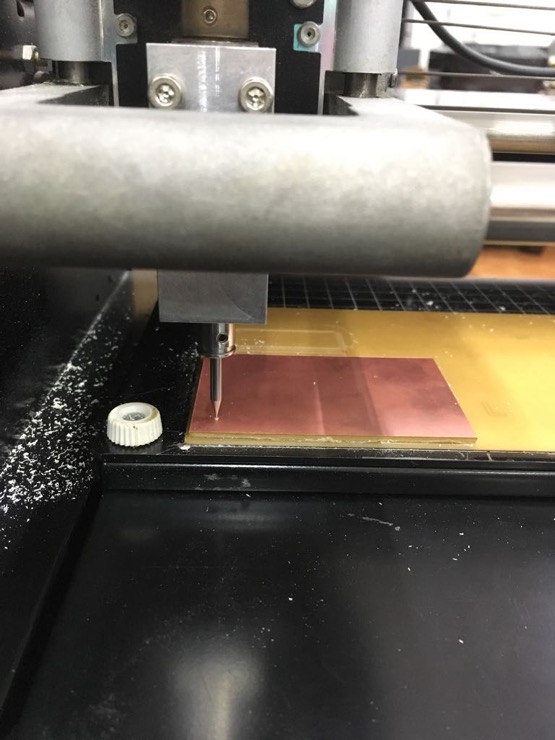
Stick the board on a double-sided adhesive tape.
Positions set and ready to mill.
Check the gap. It should have enough clearance to be able to drill into the depth of the board.
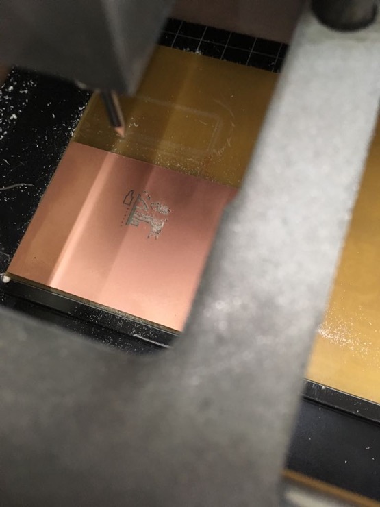
The tool went to the middle of the board, printed this and stopped. I panicked and lifted the tool up. Bad move. Go to next image to find out why.
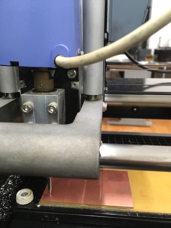
The machine has this contraption to replace the covering lid. If this loosened, the machine thinks that the lid is lifted and stops milling.
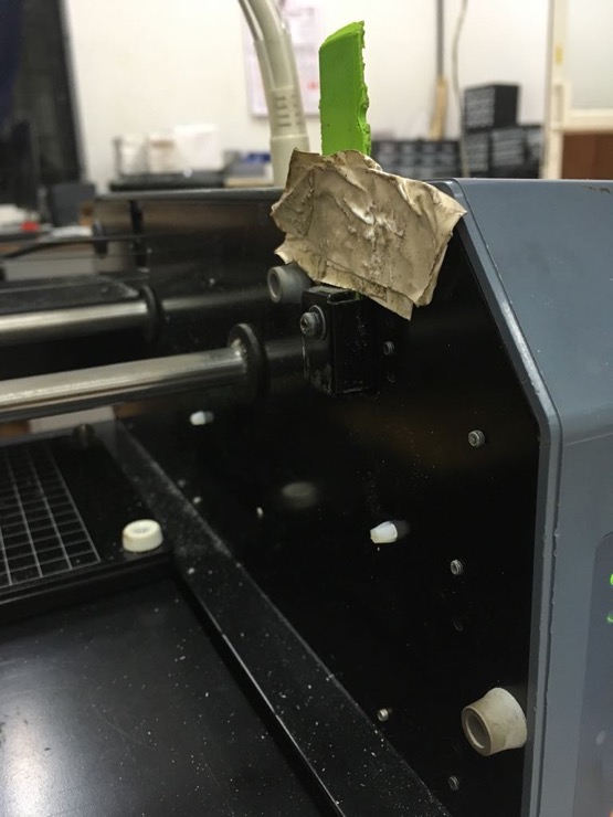
This was what had happened and I should have just pressed on this green thingy to tighten the connection and continue the job. But I moved the tool, so no way the machine would be able to continue from where it stopped.
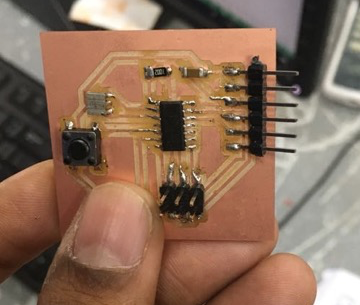
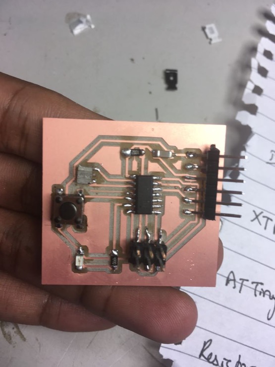
After milling the second board and soldering the components on it.
I tried connecting my board to the programmer that I made last week. I followed the steps to modify the fuses. I kept getting errors in connection. I spent a lot of time debugging with the help of Vinod, our instructor, whose eyes can substitute for the multimeter! We found three mistakes: (1) Machine had not milled away one portion which connected the resistor to ground. (2) My design had an issue. I had missed the crucial connection of resistor to the 'Reset' pin in the IC. (3) There was a short circuit caused by solder between two pins of the FTDI.
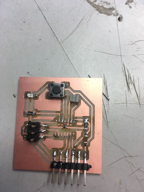
Had to desolder and remove the IC to make a new connection between resistor and reset pin of IC. The new connection was made using solder and the IC was soldered back on top it on the board.
The new connection was made using solder and the IC was soldered back on top it on the board.
Test the PCB
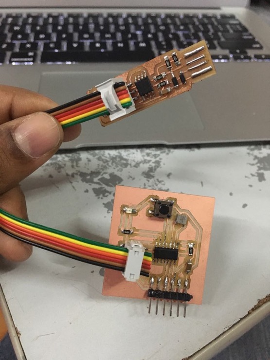
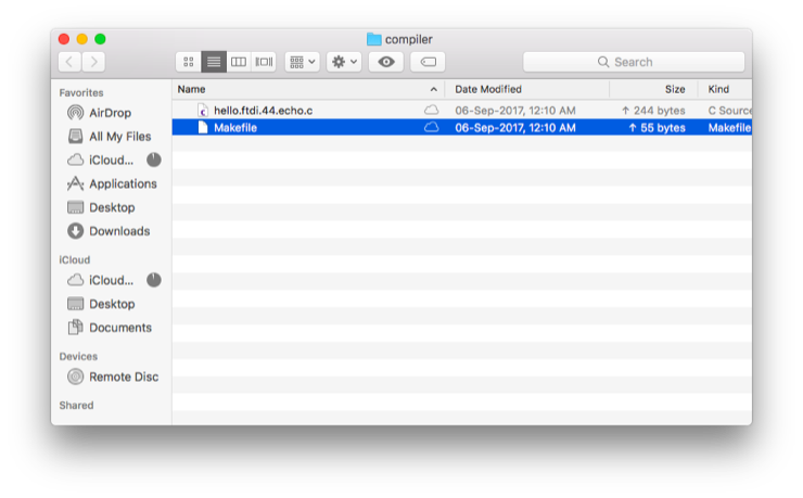
Connected the board to my ISP programmer and plugged the ISP into my PC. Downloaded the .C and .make files from the 'Embedded programming' page.
Rename the .make file to just 'Makefile'. The .c and the make files have to be in the folder. Open the terminal from within this folder.
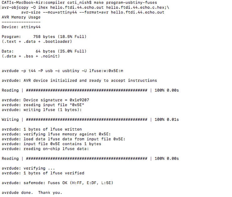
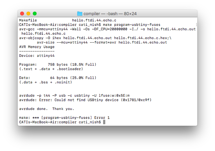
Type 'make program-usbtiny-fuses'. I got this error because the ISP was not well-inserted into my PC. I sorted this out.
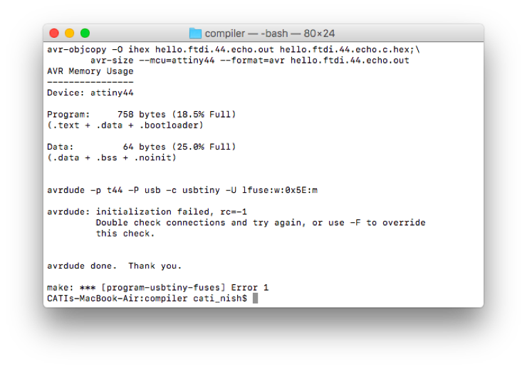
I got the 'Initialization failed. rc=-1' error multiple times and I had to go back to multimeter and our instructor, Vinod to debug. The mistakes and the steps I had to go through for debugging have been explained in the previous section.
'Completed. Fuses OK finally. Yet to check if the 'echo' program is running.
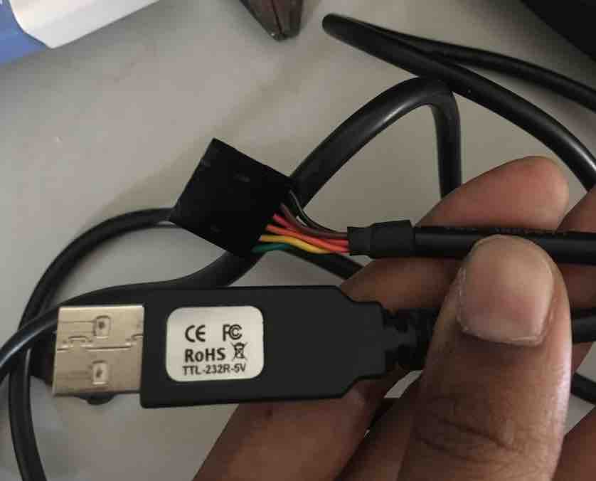
The USB to TTL serial cable(5.0 V) that we used to connect from the FTDI pins on our PCB to the USB port on the laptop.
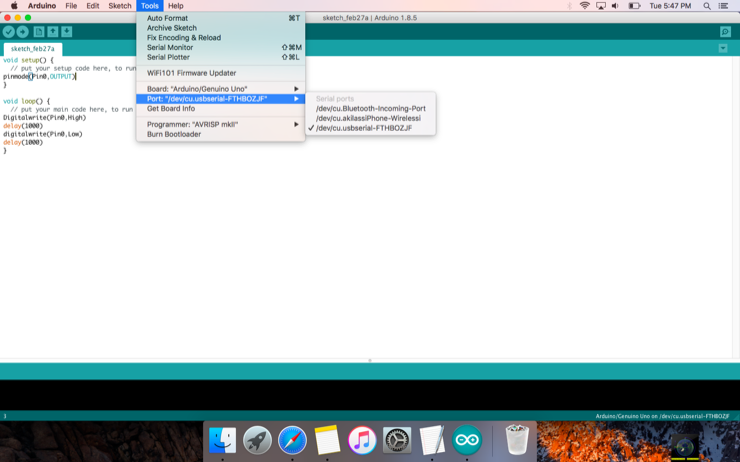
I used the 'Arduino' software to check the program. Choose Tool>Ports>USB serial port.
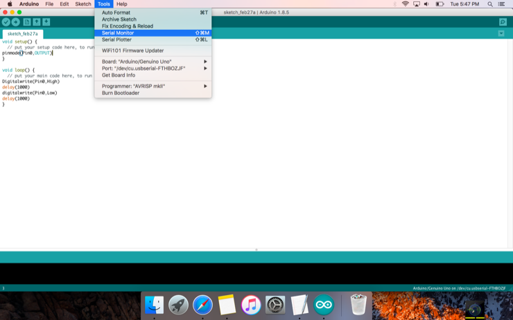
Choose Tools > Serial monitor.
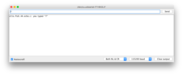
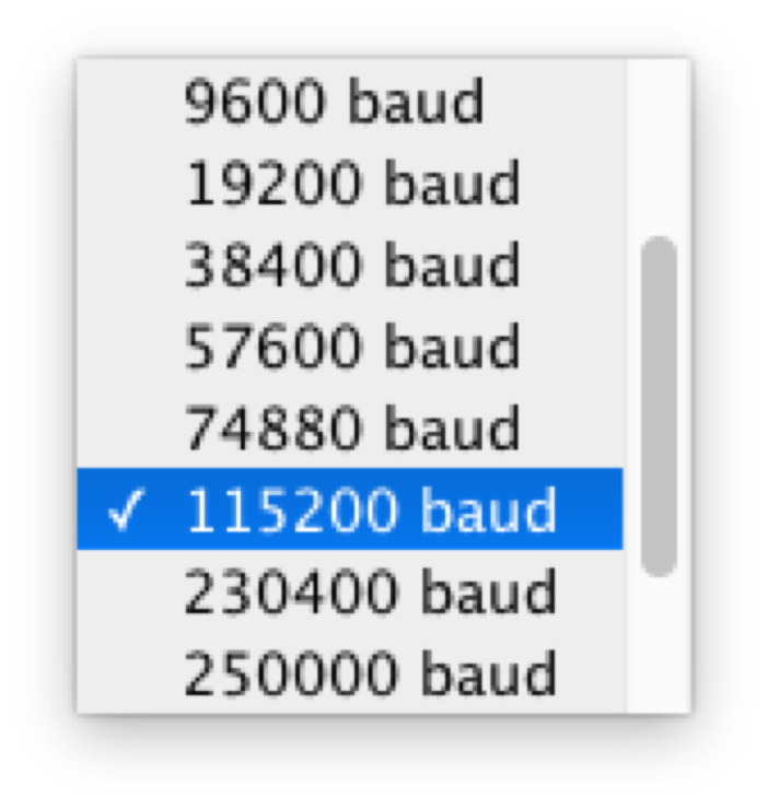
Serial data speed is measured in terms of baud rate. According to electronicdesign.com, 'Baud rate refers to the number of signal or symbol changes that occur per second. A symbol is one of several voltage, frequency, or phase changes'. We had to choose 115200 baud for our PCB, which means the means that the serial port is capable of transferring a maximum of 115200 bits per second.
Checking the 'echo' program by typing in a letter. The program returns the same letter.
Typing in more letters and checking.