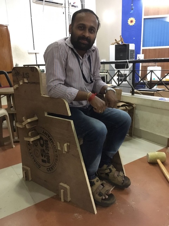
This week's assignment was fun. It was nerves-racking to get the design right to make a usable end-product. The scale of the machine and materials made it all the more important to make as little mistakes as possible. I tried my hand at an adaptive chair for children with disabilities. It turned out fairly well for the first attempt (I could sit on it!). But I can spot many defects with the design which I'm motivated to set right and try making the chair again. An adaptive chair has been an urgent need for a long time at my workplace (NISH) where kids with cerebral palsy visit for therapy. I hope to make this usable for them.
Group assignment:
Some video clips from the week..
Characterizing the machine: test runout, alignment, speeds, feeds, and toolpaths.
This document gives very simple and clear instructions on how to switch on the machine, set the zero axes and so on.
Some useful notes from a shopbot manual on 'feeds and speeds':
'A challenge of getting a good CNC cut is in selecting the best cutting speed (feed rate) and router/ spindle RPM (speed of rotation). Feeds and speeds are a critical part of machining and should be fully understood before deviating from recommended settings. A primary concern of machining is chip load, which is a representation of the size of the chips produced during cutting. The goal is to get the maximum chip load possible to increase productivity, reduce heat, and prevent premature dulling. When chip load is too small, bits will get too hot and dull quicker. When chip load is too high, the tool will deflect creating a bad surface finish and, in extreme cases, chip or break the bit.
Chip load is a function of three different parameters: feed rate, RPM, and number of utes on the tool.
Chip load is the thickness of the chunk of material taken by a tooth of the cutter. This is determined by how fast the cutter is moving forward into the material and how fast it is turning
Chip load = Feed Rate / [RPM x number of flutes].
This formula provides a starting point for determining the most suitable parameters for any cutting situation'.
Although we didn't use this formula for our assignment and relied on our instructors' experience with the machine, it is good to know this for future use.
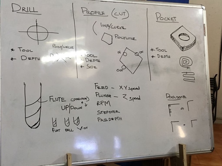
1. A few basic concepts as taught by our instructor, Yadu.
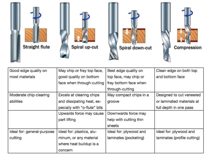
2. How to choose the right tool? Excerpts from a Shopbot manual.
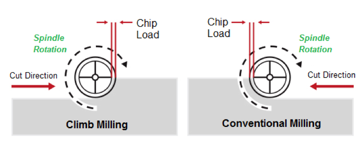
3. We could opt from either of these two types of milling. From some googling around, I decipher that climb milling is preferred for better surface finishes as the chips are evacuated behind the cut and we are not re-cutting them. Conventional milling is beneficial when machining hard materials like metals.
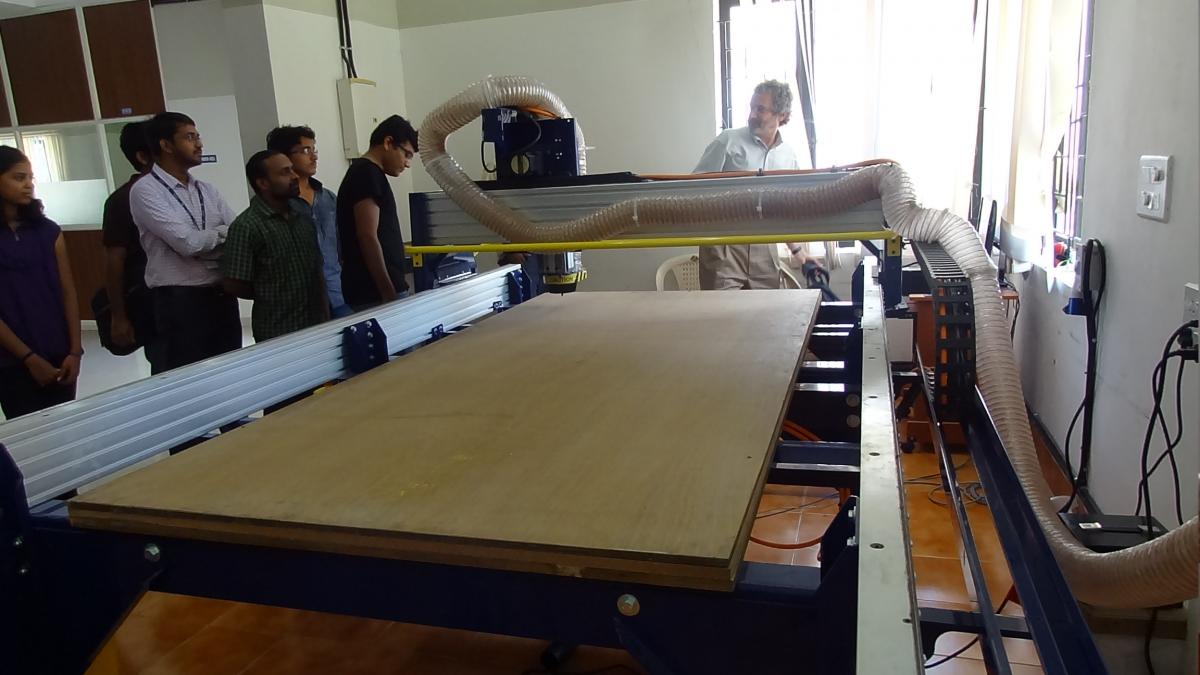
4. The Shopbot milling machine in our lab. During Neil's visit to Trivandrum.
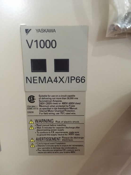
5. The V1000 is the vector control motor, which drives the movement of the spindle on the shopbot bed. As per yaskawa.com, V1000-4X is a version of the standard V1000 in an integral enclosure which provides the protection required in tough washdown or dust-tight environments.
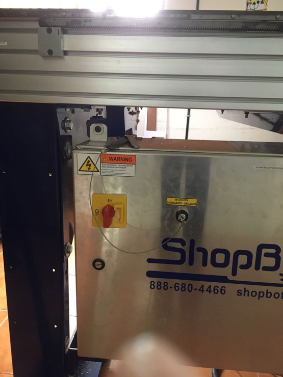
6. The on/off switch for the Shopbot and the key to engage/disengage the spindle to which the cutting tool is attached.
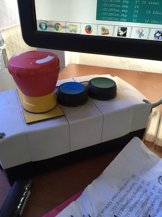
7. The red button is for emergency stop. The blue button is to reset and the green button is to start the spindle.
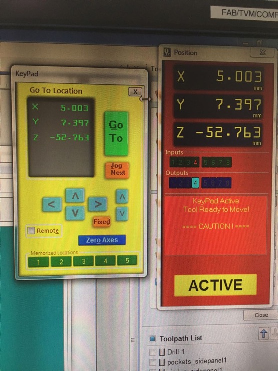
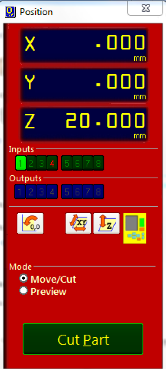
8. The Shopbot machine control interface from the connected PC. The red window shows the position of the tool and the yellow window is the keypad to control it along the X, Y and Z axes. The 'Zero axes' option is found here too to set the origin.
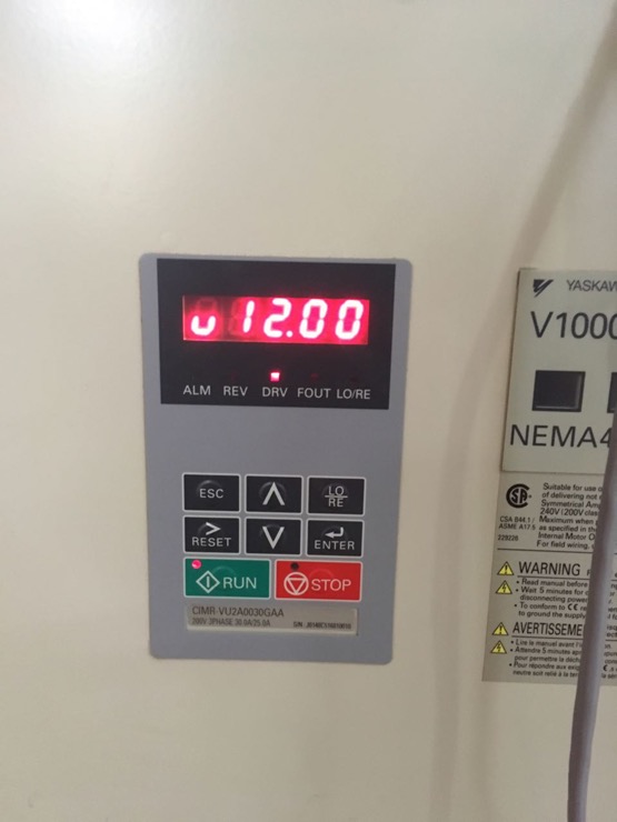
9. The small control panel on the machine displaying the spindle speed (12000rpm).
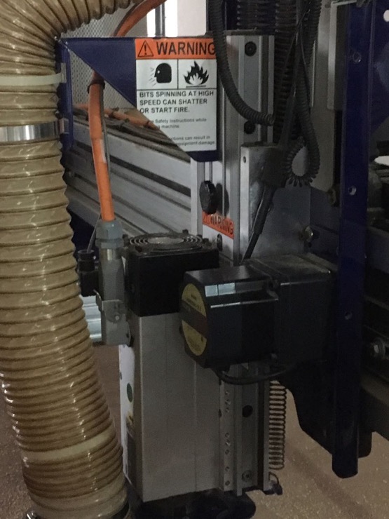
10. The warning note on the machine.
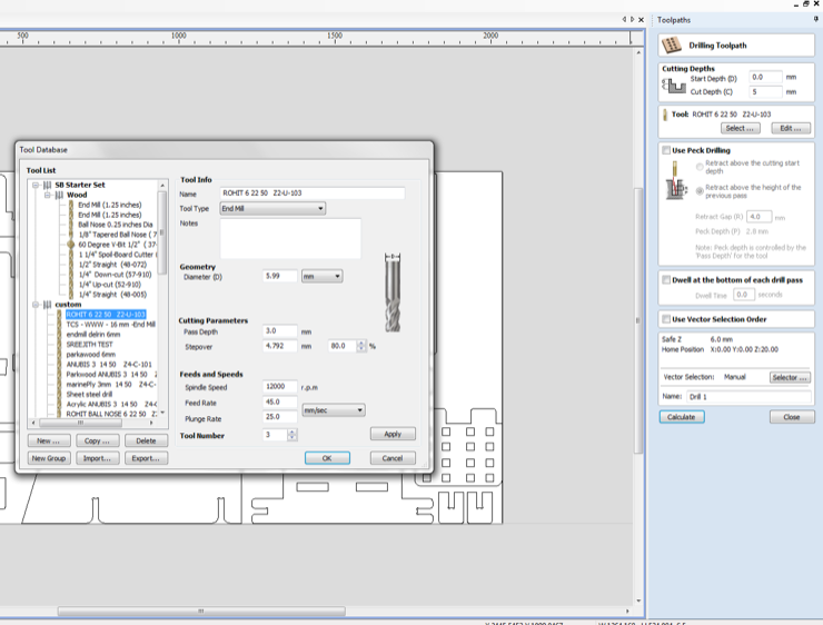
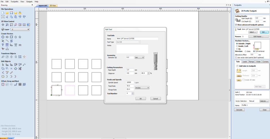
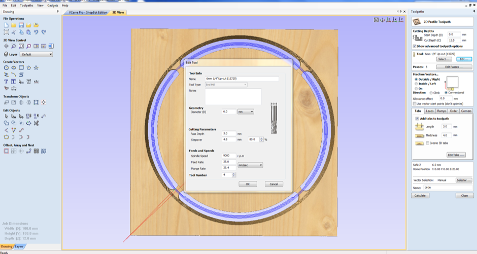
11. Open the 'VCarve' software and choose the tool and parameters for cutting, feed and speed.
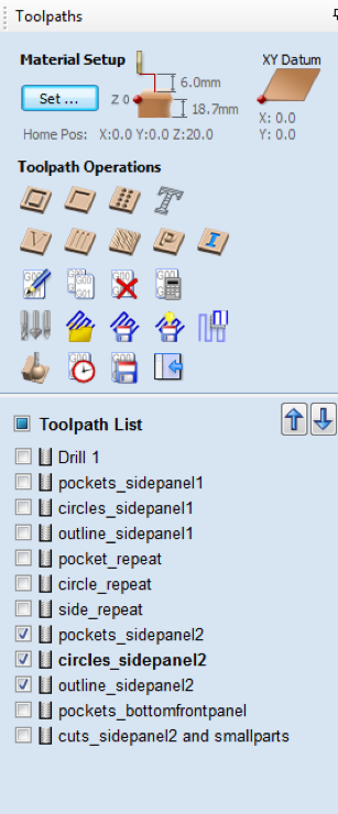
12. Toolpath operations and list of toolpaths. To edit a toolpath, select it.
13. The XYZ co-ordinates of the tool position. In our lab, the longer side of the table is the x-axis and the shorter side is the y-axis. The options for zeroing the axes are below.
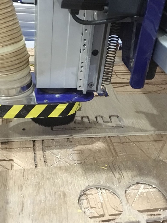
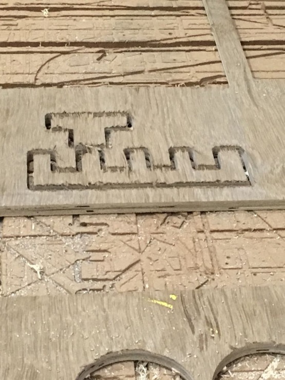
14. The machine milling our test design.
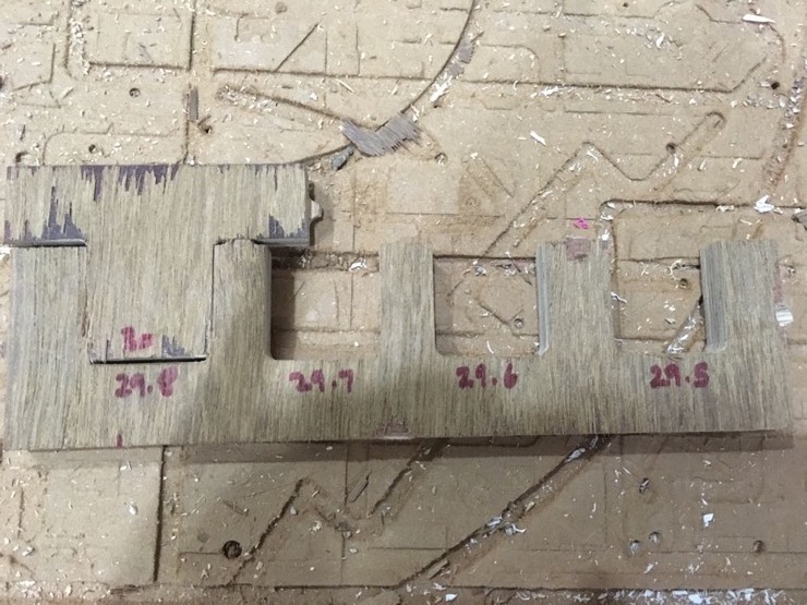
15. Design to test tightness of fit. The female slots are of varying lengths.
16. The T-shape had to be hammered into the 29.8mm wide slot. However, after a few days, we saw that the T-shape could be prised into the 29.5mm wide slot as well. Wonder how?
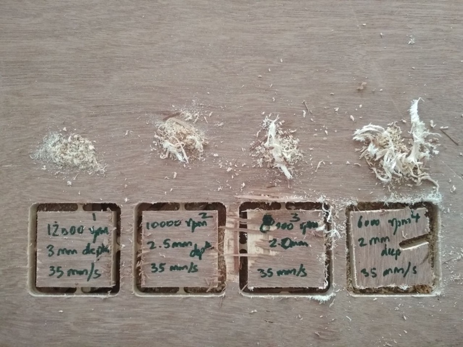
17. We milled a few square shapes with varying parameters for cutting, feed and speed. Toolpaths are generated for each square. The shapes with the same tool speed (in rpm) can be grouped together, even if they have differing depths and/or speed.
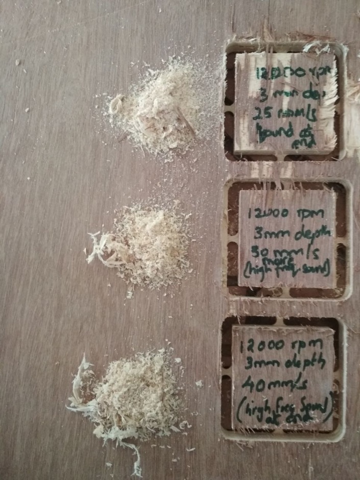
18. The quality of cutting deteriorates when both spindle rotation speed and depth are decreased. It is best at 12000rpm and 3mm depth, 35mm/s speed. For the same speed, at 6000rpm and 2mm depth, the tool loosened.
19. At 12000rpm, we heard a high frequency sound, especially at higher speeds.
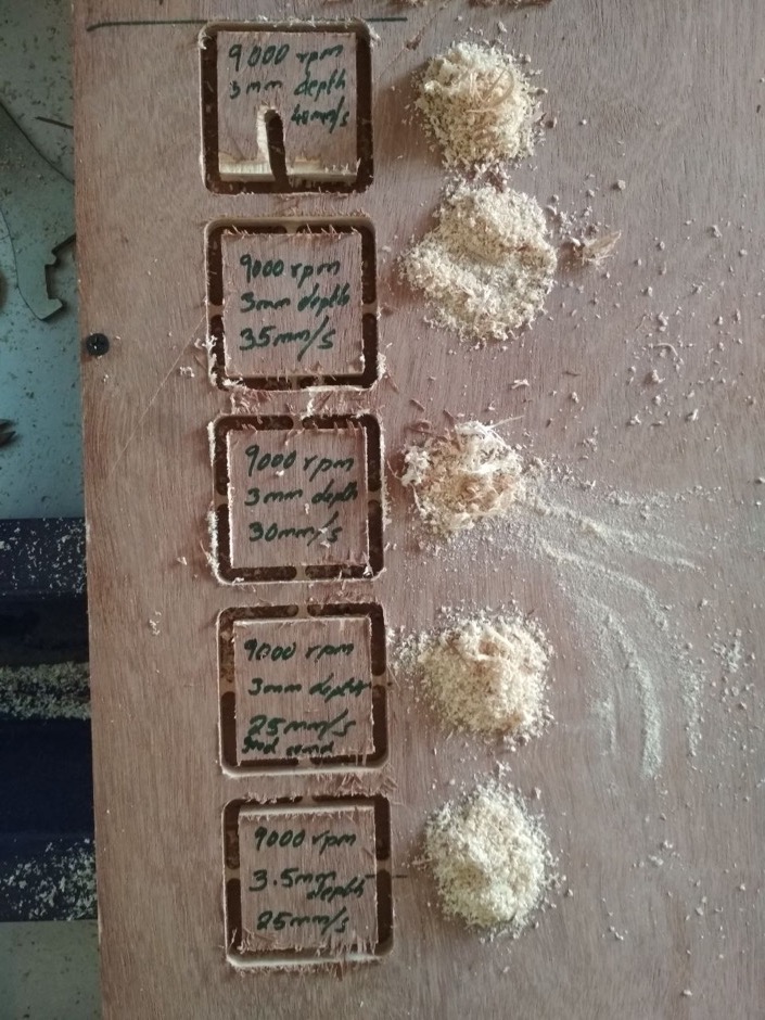
20. It seemed to us that the best cutting quality (+good chip texture+good sound) was obtained with the following parameters: 9000rpm spindle speed, 3mm cut depth and 25mm/s tool speed.
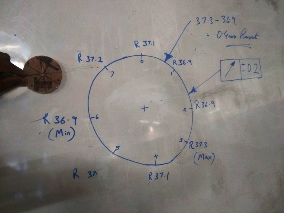
21. We cut a circular shape to measure the tool run-out. Run-out is due to the inaccuracy of rotating mechanical systems, when the tool or shaft don't rotate in line with the main axis.
22. The radius of the circle was measured at different points throughout the circumference. Half of the difference between the maximum and minimum values gives the value of the tool run-out. We measured : 37.3 - 36.9 = 0.4mm; Run-out= +/- 0.2mm
Designing an adaptive chair for kids with disabilities
It has been a long-pending dream to make adaptive furniture like
this or
this with options to adjust the angle and height of the different components. I used Fusion 360 to design a press-fit model adaptive chair.
Download the design files here:
(.dxf) and
(.f3d)
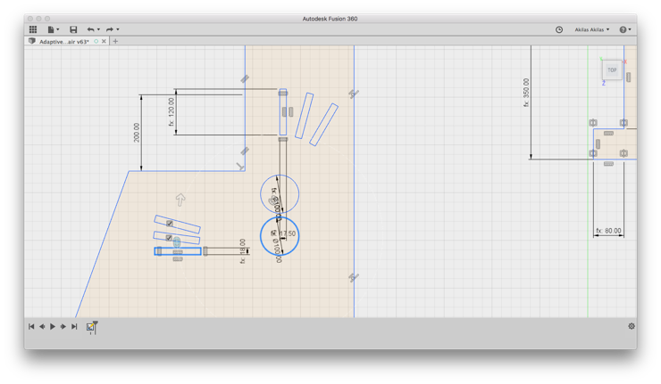
1. The biggest difficulty in designing the chair was the placement of the slots for inserting the removable plank, to adjust the seating angle. This was the first design of the cross-section of the chair side-frame.
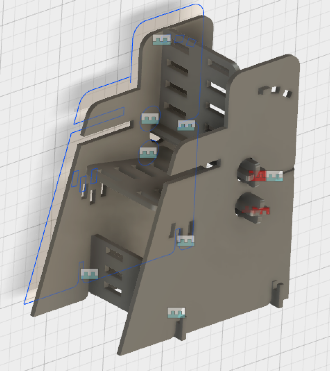
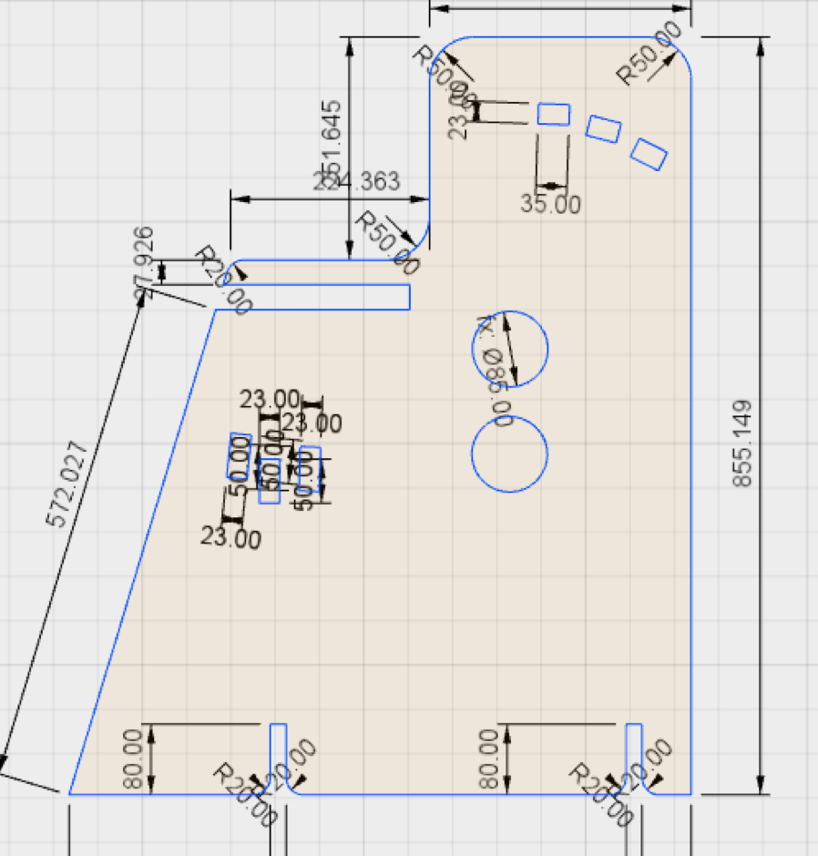
2. This is the final sketch design of the side panel of the chair.
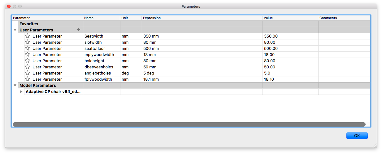
3. The design is parametric. Here is the list of parameters used.
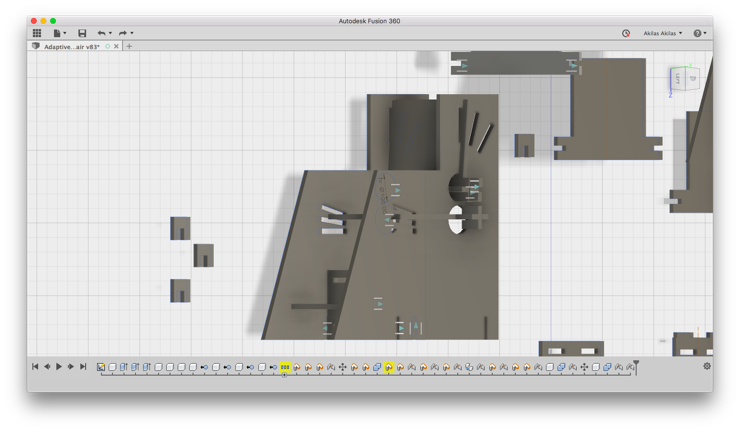
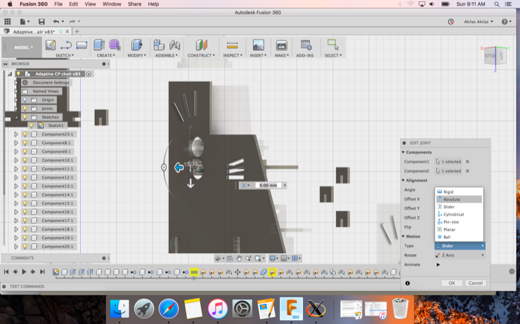
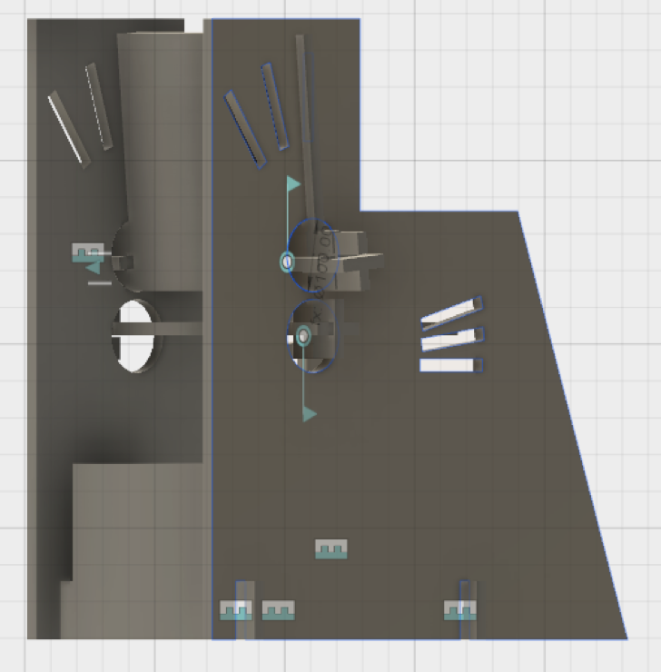
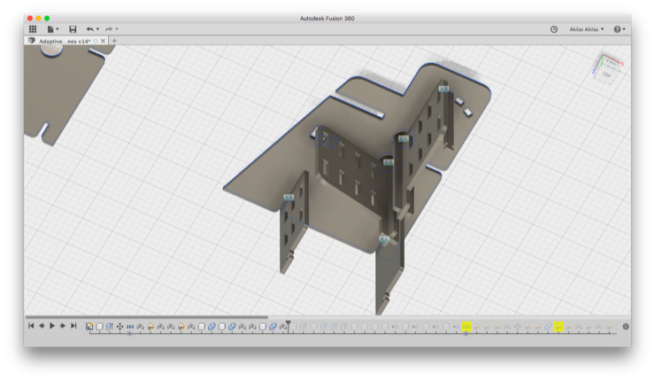
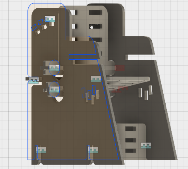
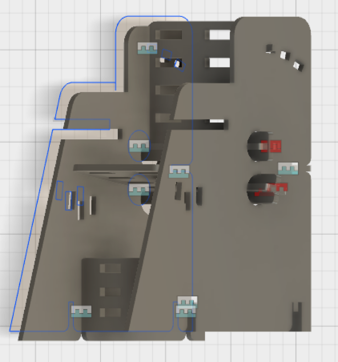
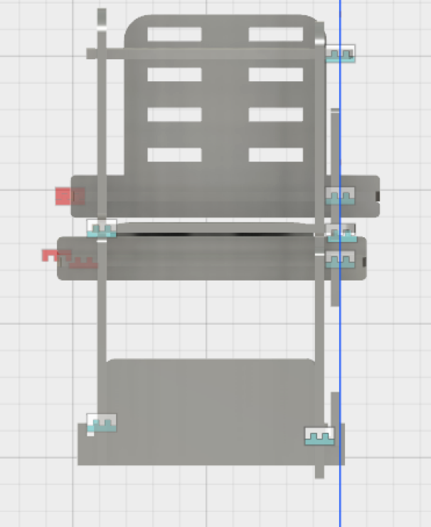
4. After creating the 3D models, assembling the components in Fusion was a good exercise to check the design. I could spot a few design flaws that I could immediately rectify. I realized that this is a useful feature, to avoid mistakes before actually milling.
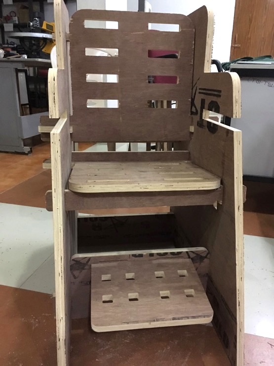
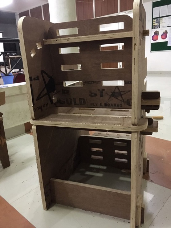
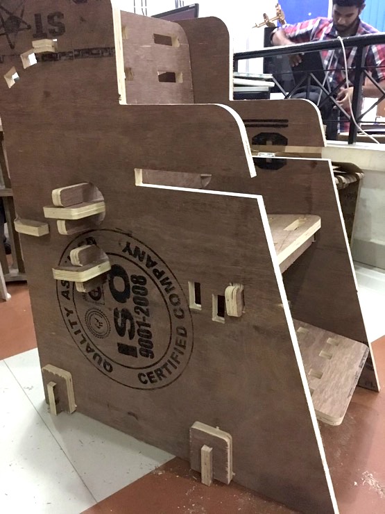
Milling and assembling the parts
When assembling, I realized that I should have machined both the male and female parts of the joints. I had designed the female slot, based on the assumption that the plywood would have a uniform thickness of 18mm throughout. Unfortunately, that was not the case and the joints turned out to be loose at some places, wherever the plywood was less thick.
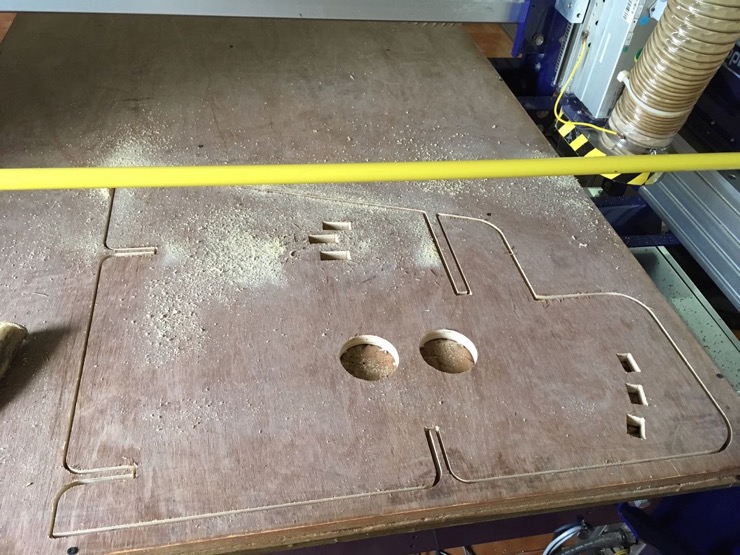
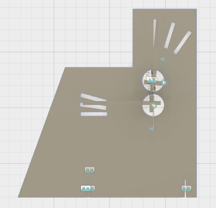
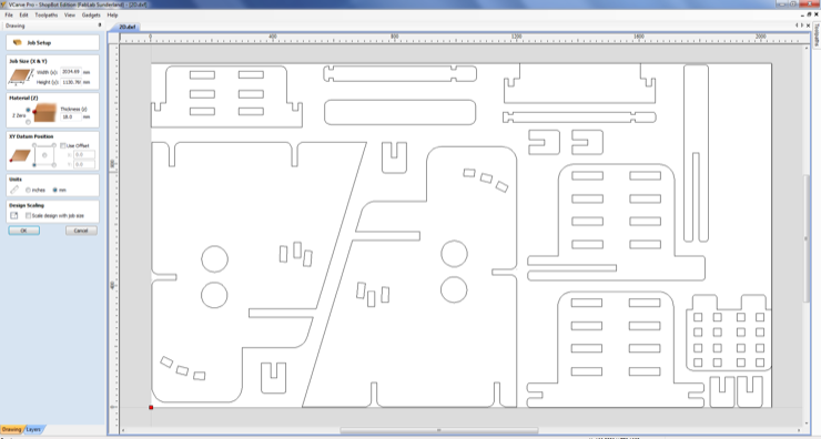
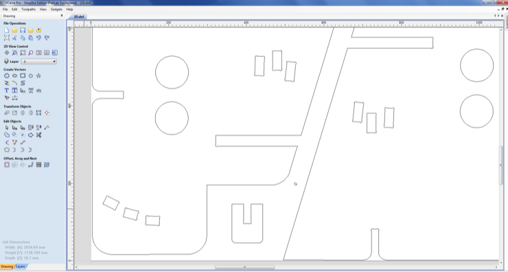
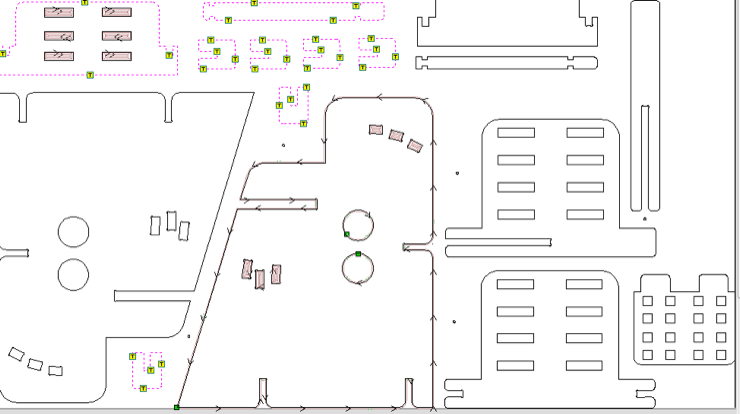
Laying out the different components for milling. Yadu helped me do this so neatly.
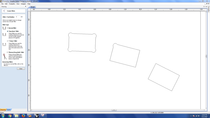
Adding 'dog-bone shape' to wherever there is a right-angle cut.
Generating the toolpaths - 'pockets' for the holes and 'cutpath' for the cut-outs.