Week 11: Input Devices
Group assignment:measure the analog levels and digital signals in an input device
Individual assignment: measure something: add a sensor to a microcontroller board that you have designed and read it
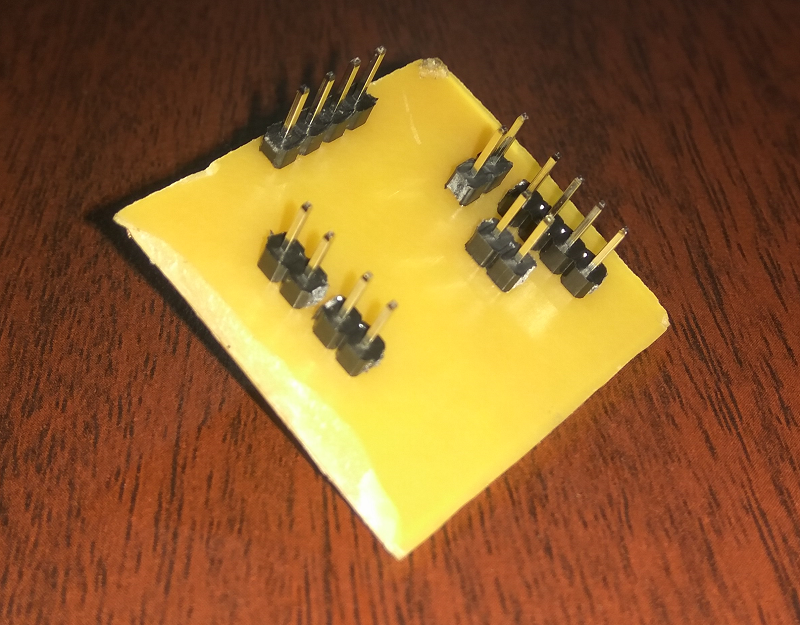
In this week we need to connect a sensor to a microcontroller and read that value, I plan to make something that will be useful for me. So first I decided to make a microcontroller board, I choose Attiny44 and replicate the board used in the Embedded programming week with site changes, I remove the Led and Pushbutton from the design and add header pins to that so that I can connect it with more any sensors I want. Soextra header pins are provided to connect VCC and GND . For designing, I am using eagle software familiarise in electronic design week
Designing
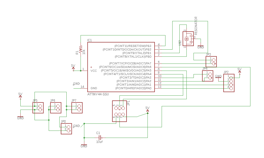
In Eagle, I choose the Attiny44 package from the fab library that I added on electronic design week, Reset pin is pulled up by connecting 10k resistor series with VCC and Capacitor of 1uf connected across Vcc and GND.ISP header connected to respective MOSI, MISO, SCk, VCC, RESET and GND pins of Attiny44.PA2, PA3, PA7 and PB3 from ATtiny 44 connected to JP3 and JP4, JP2 is used to connect RX and TX.Schematics is creatby refering the electronic design week
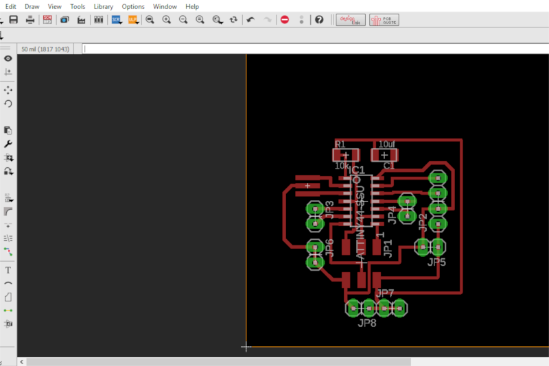
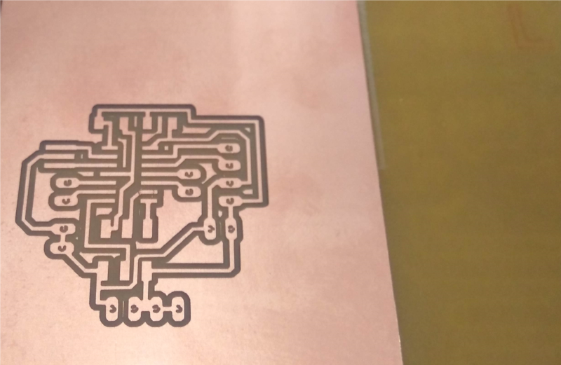
After completing the schematics next, I go with board design. Rather than automatic routing manual routing makes pcb, more excellent and perfect. Here I give 16 mm clearance and 18mm width.
PCB Milling
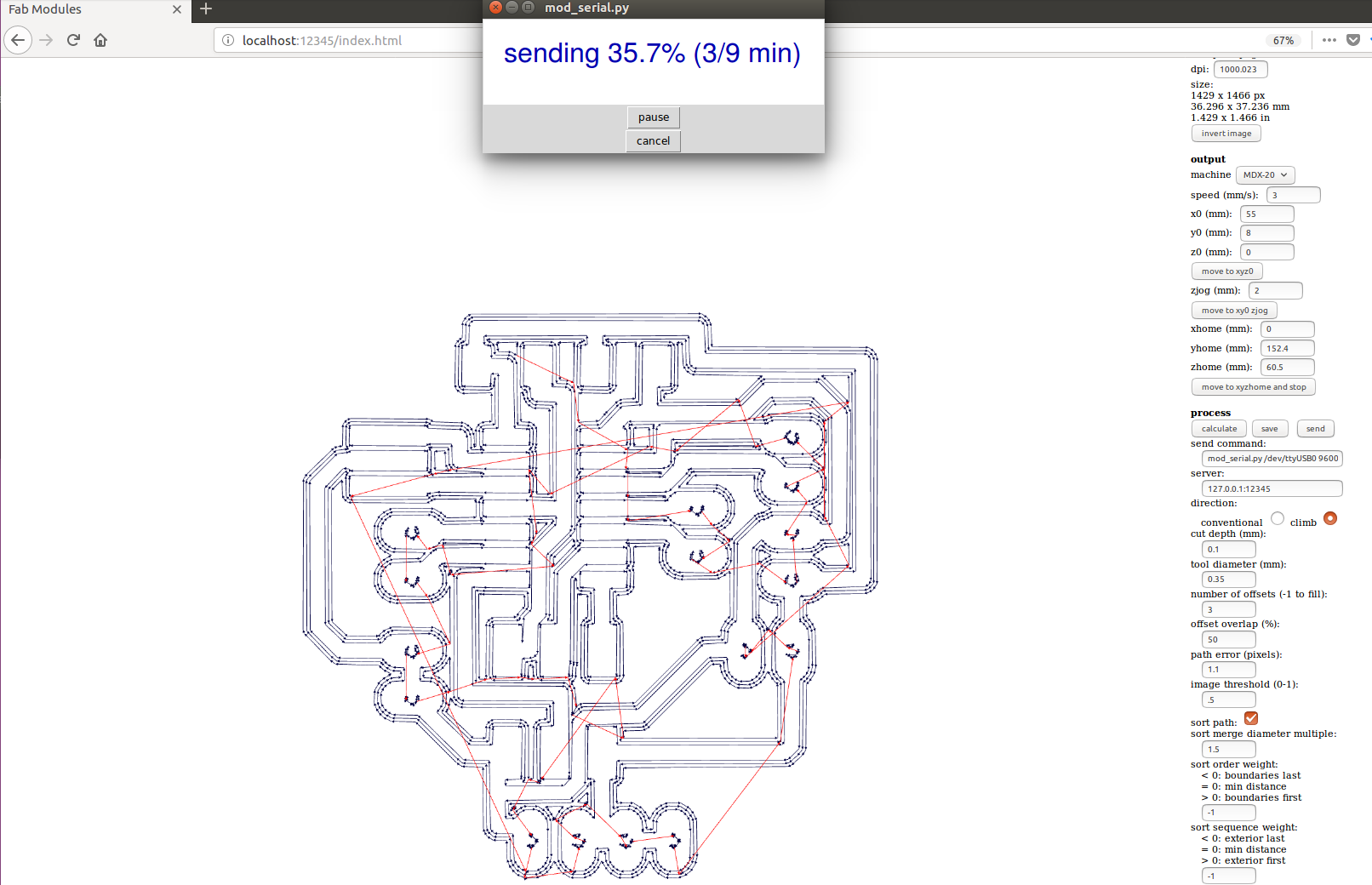
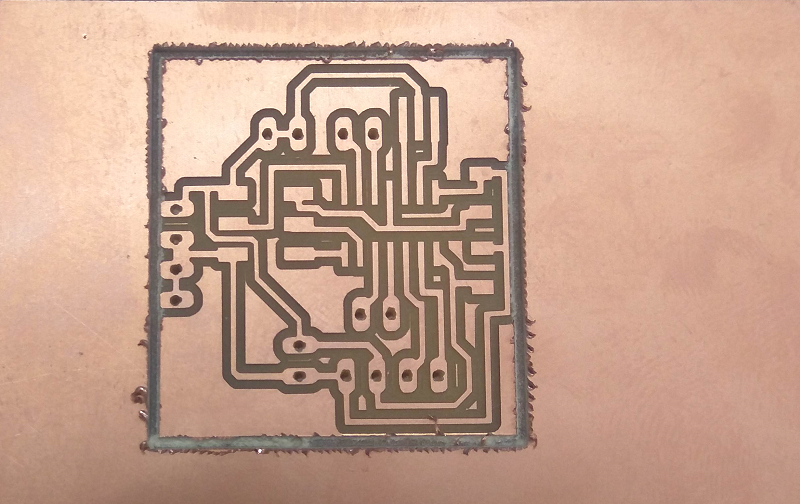
PCB production process is familiarise in electronic production week so the learnings from that week helps a lot to operate the Modella MDX 20 for PCB milling in this week I have used 1/64 bit to mill the pcb, after design i check DRC no errors founded so I export the monochrome image of pcb and give Mods software to send G-code to Rolland mill to perform cutting. While giving tool diameter a 0.39mm tool path not shown is not the perfect one, design in eagle is perfect, so I change tool path to 0.35 it shows complete tool path, and I reduce speed to 2 and perform the mill, it takes 15 Minutes to perform milling .
After that i change tool to 1/32 to perform cuttting and drilling , first i perform drilling and then i go with cutting , when cutting startes when i loock i feel some trouble , cutting tracck go near to traces so even after one round of offset cut i stop the machine and take out and go to use haxsaw to cut the pcb .
After cutting the pcb, take components from the lab, and perform soldering, its go very fast than usual, after soldering connect pcb connected with my USBtiny ISP made in electronic production week is used check is it working using below command in terminal. Same USBtiny is used for programming the entire week.
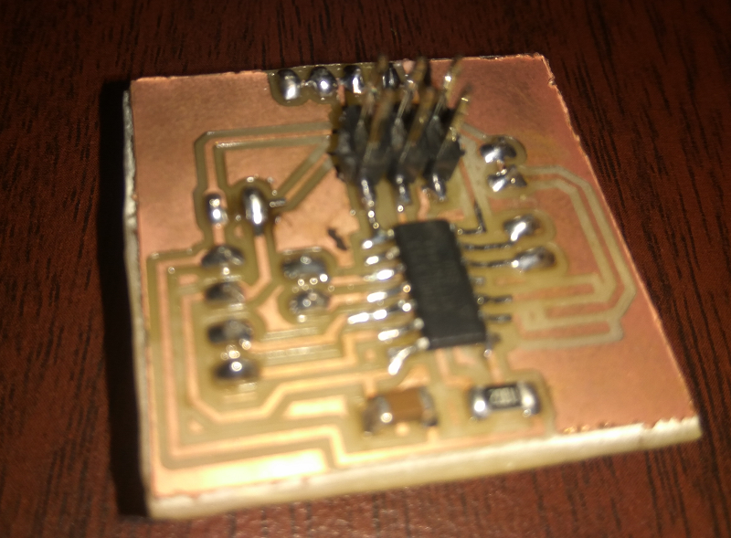
sudo avrdude -c usbtiny -b 9600 -p t44
Result shows that my PCB is working good , next i need to add some sensor to my board
My Work
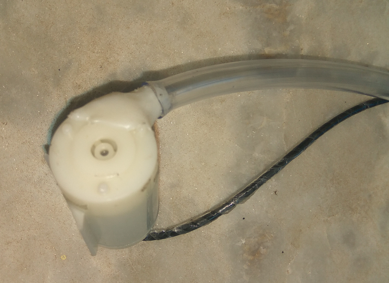
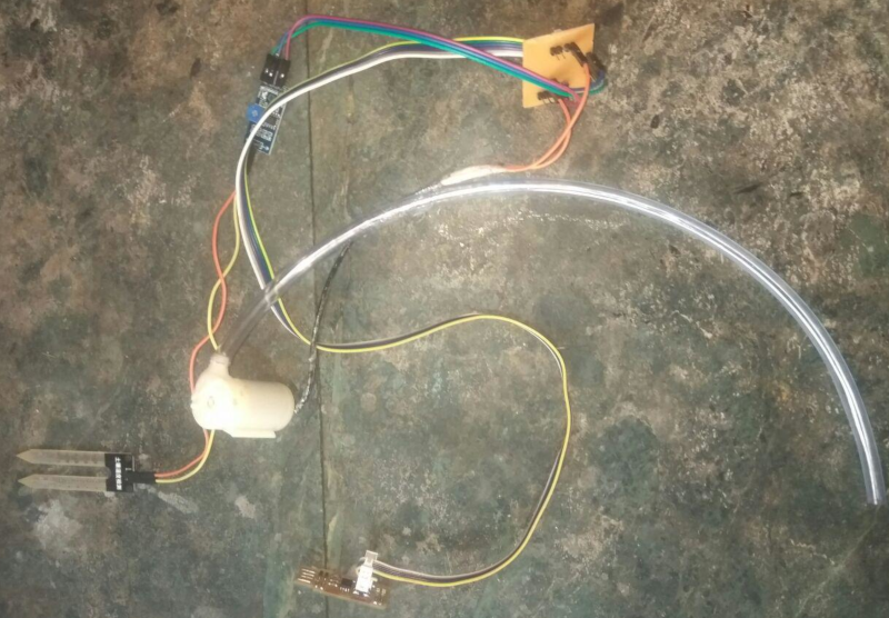
When I see my flower pot in my home I decided to make an automatic watering system that measures water quality of the solid and spread water for the plant. To do that I need some material, so decided to check my sensor kit and I found a soil moisture sensor also I take a small 5v water pump that I used in my fish tank .First I take water pump and fit it with a small tube, actually its tip is already broken, so I add some hot glue to make it, next take soil moisture sensor
About Soil Moisture sensor
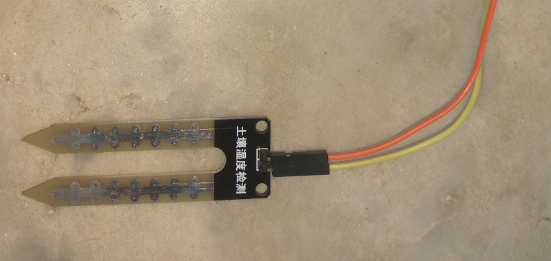
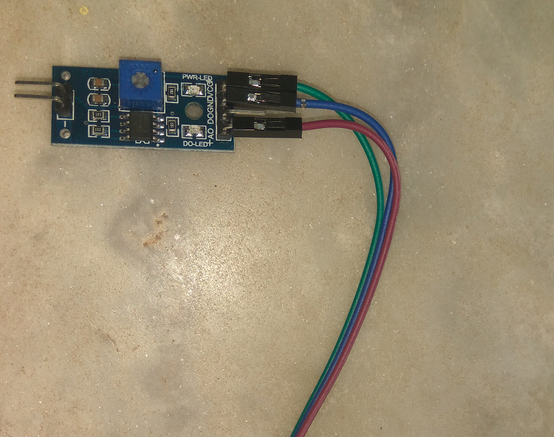
soil moisture sensor consist of two components, one is a two-legged part, which measures the water content, this has two header pins. This header pins connected to next part, which is an Amplifier/ A-D circuit which is in turn connected to ATtiny 44. Amplifier has a Vin, Gnd, Analog and Digital Data Pins means that we can get the values in both Analog and Digital form.
soil moisture sensors are designed to estimate soil volumetric water content based on the dielectric constant of the soil. Dielectric constant means the ability of soil to transmit electricity of water. Which means constant dielectric increases as the water content of the soil increases. So Measurement of dielectric constant gives an unpredictable estimation of water. The soil moisture sensor consists of two legs which are used to measure the dielectric constant of soil which gives the volumetric value of water in the soil
Details are taken from this source
Connection with Soil moisture sensor with Attiny 44
- Connect two pins from part 1 to two pins of Amplifier ciruit ( part2) using jumper wires
- Connect VCC , GND and AO of Amplifer circuit to 5V, GND and PA3 of ATtiny 44 pcb
Code
In Embedded programming week I familiarise on the Attiny44 IC and program it using Arduino IDE, I decided to go all my weeks with Arduino IDE it's quite simple to program.First, I go with measuring soli humidity and shows the value in Serial monitor.Attiny44 IC does not equip with Hardware serial, so we need to go with Software Serial communication to see the results in the serial monitor. For performing we need to use software Serial library, it is already installed in Arduino core. #include<SoftwareSerial.h > which calls the library, and SoftwareSerial serial(0,1) creates an object named serial, 0 refers to pin (PA0) set as Receiver pin and 1 for the pin (PA1) set as transmitter pin. For more details regarding SoftwareSerial Refer this
The soil moisture sensor is an analogue Sensor, so we need to connect it with an analog pin to read the value from that.Attiny44 consist of 10it analog to digital converter means that it will map input voltages between 0 and 5 volts into integer values between 0 and 1023. Value can be read using analogRead(pin-number)
// created : 13 April 2018
// author : Amith G Nair
#include <SoftwareSerial.h>  // call the software serial libaray
SoftwareSerial serial(0, 1); // create serial object
 int x
void setup() {
  serial.begin(9600);         // baud rate for serial communication
}
void loop() {
 x=analogRead(A3);      // read the Analog port A3 which sensor connected
 serial.print("Soil Humidty level:");
 serial.print(x);
 serial.println();
 delay(1000);     // delay for 1000 mili seconds
}
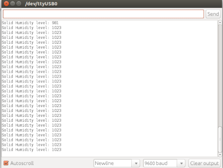
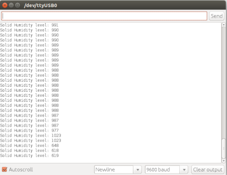
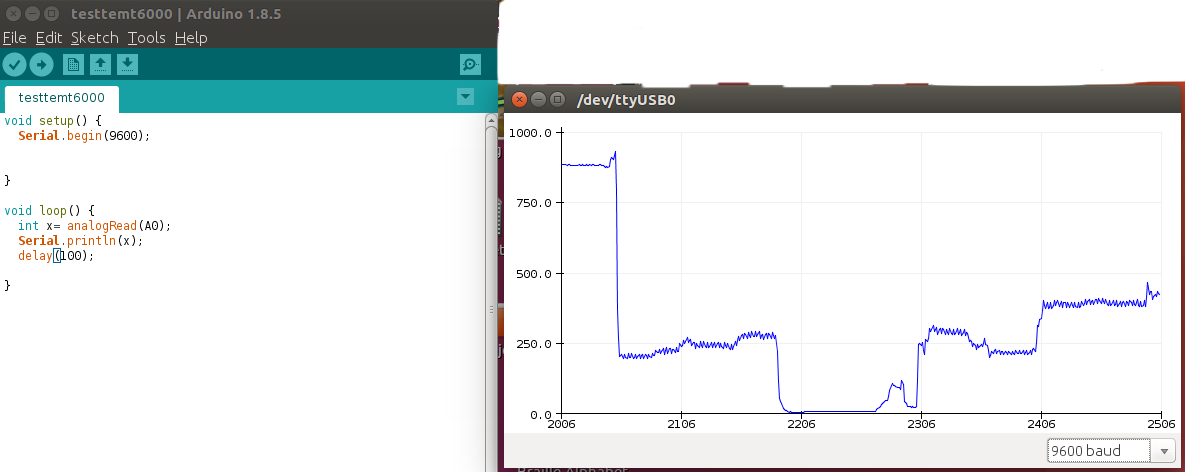
After making the connection and take 4 cups of soli with different humidity and read each level and not down. Verifying the code, upload it to the board and open the serial monitor. I will see the sensor data on the monitor changed when dip the sensor leads in various cups
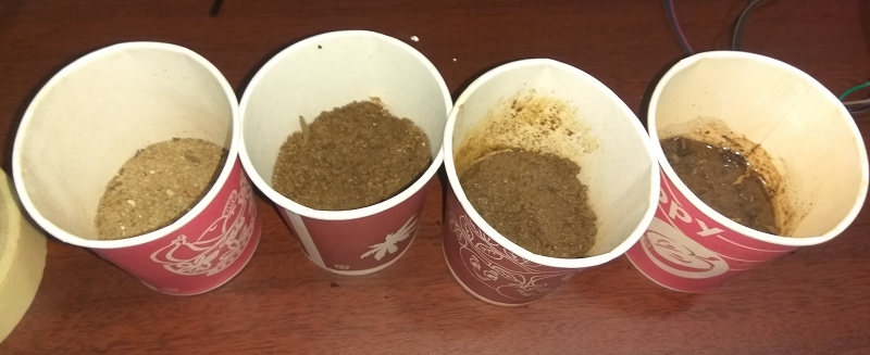
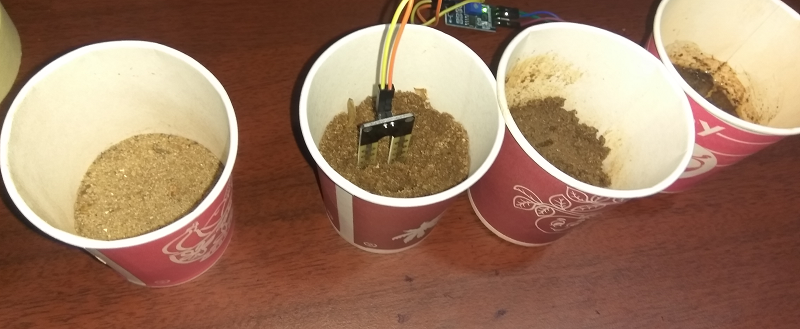
From that i under stand that if soil is very dry sensor shows a value of 1023 while we perform analog read and value goes down when water content in soil decreaseses
Hereafter reading the serial value using the analogRead function then it performs the If condition, which checks the humidity level and then performs the operation function. I declare two functions named motor() for turn on the motoron(), and motoroff() turn off the motor.Next i connect motor pump with circuit so that when water content in soil falls below threhold level, water pump will on for 2 minutes .I connect VCC of Motor with PA7,because PA7 goes high means 5V will get on these pins . Its enouf for the working of this motor .
// created : 13 April 2018
// author : Amith G Nair
#include  <SoftwareSerial.h >  // serial libaray intialization
SoftwareSerial serial(0, 1);  // RX, TX
int sensorPin = 3;   //sensor connecting pin
int sensorValue = 0;
void setup() {
serial.begin(9600);  // set the data rate for the SoftwareSerial port
}
void loop() {  // run over and over

 sensorValue = analogRead(sensorPin);
 serial.print("Solid Humidity level: ");
 serial.println(sensorValue);
 delay(1000);
 if (sensorValue>750)
 {
   motoron();
 }
 else
 {
   motoroff();
 }
}
void motoron() // switch on the motor
{
analogWrite(2,1023);    // turn ON the motor connected to pin 2
serial.println("Motor is on");
}
void motoroff()   // switch off the motor
{
analogWrite(2,0);      // turn off the motor connected to pin 2
serial.println("Motor is off");
}
Work With G-61 Accelerometer
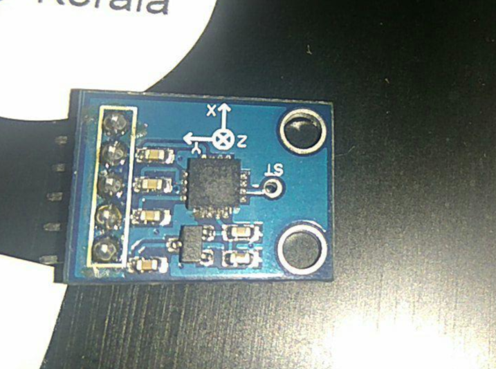
GY-61 DXL335 3-Axis Accelerometer Module is a three axis accelerometer sensor module based on ADXL335 integrated circuit. The ADXL335 is a triple axis accelerometer with extremely low noise and power consumption. The sensor has a full sensing range of +/-3g. It can measure the static acceleration of gravity in tilt-sensing applications, as well as dynamic acceleration resulting from motion, shock, or vibration 3.3V voltage regulator to power the ADXL335 so power provided should be between 3.3V and 6V DC.
Details are taken from this source
Using this module we can measure
- Acceleration in in three directions x, y, z;
- Angles and orientation
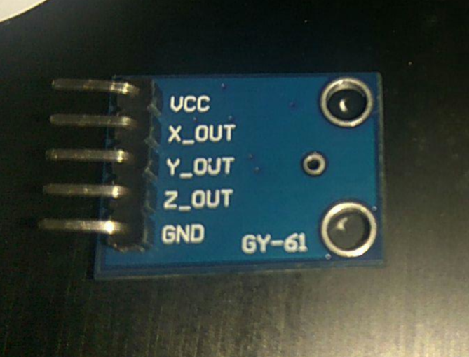
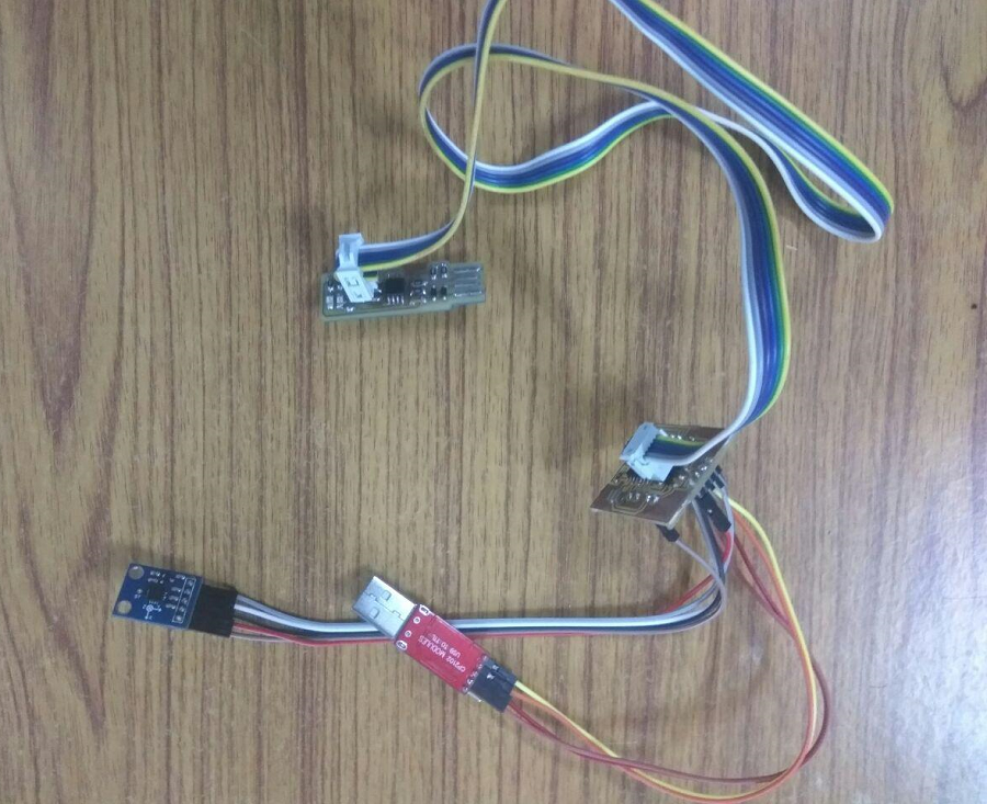
In order to use the accelerometer i powered the G-61 board 5v and gnd and also connect x, y and z output from sensor is connected to PA2, PA3 and PA7 of Attiny44 and Read the analog values
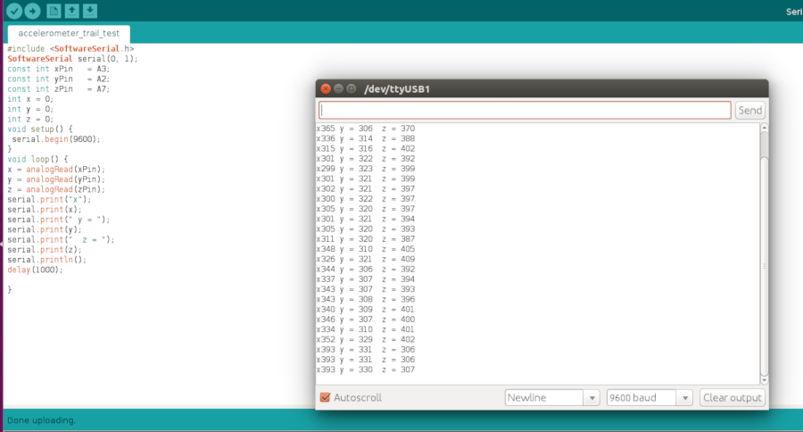
Code
// Created by Amith Gopakumar : April 15 2018
#include  <SoftwareSerial.h > // call the serial library
SoftwareSerial serial(0,1);
const int xPin =A3;
const int yPin =A2;
const int zPin =A7;
int x =0;
int y =0;
int z =0;
void setup() {
 serial.begin(9600);

}

void loop() {
 x=analogRead(xPin);  // read x value
 y=analogRead(yPin);  // read y value
 z=analogRead(zPin);  // read z value
 serial.print("x");
 serial.print(x);
 serial.print("y =");
 serial.print(y);
 serial.print("z =");
 serial.print(z);
 delay(1000);
}
Group Assignment
The sensor is a module or a chip that observes the changes happening in the physical world and sends the feedback to the microcontroller. Microcontroller accepts two types of input they are digital and analog
Analog sensors sensed the external parameters and given output in a range of 0 to 5V. for example if we are using LDR sensor module. In 9.00am it gives an output of 3v, and 11.am output is 4v, and 1 pm output is 4.5v, and in night output is 1v. it shows that analog sensors measure the quantity not only the presence of something.
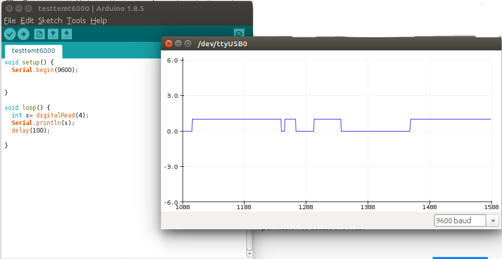
Digital Sensor produce discrete values (0 and 1). Discrete values often called digital (binary) signals in digital communication.for example if we are using PIR sensor .it gives output of 3.3v when motion is detected and 0v were no motion detected.Here We used Arduino connected with PIR sensorand run the code and made the plot.