Week 13: Interface and Application Programming
Group assignment:Compare as many tool options as possible
Individual assignment:Write an application that interfaces with an input or output device that you made
This week assignment is to write a application to interface the input and output. I plan to start with MIT app inventor and after that try others.
I decide to on and off a lamp using smartphone. To do that we need to communicate MCU board using Bluetooth of phone. So, I connect Bluetooth Module HC-o5 with MCU board that I developed in output week.
HC-05
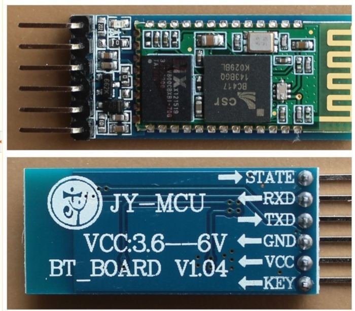
HC-05 is Bluetooth module help us to making a communication between two separate MCU Boards or MCU with smartphones. HC-05 module is a Bluetooth SPP Serial Port Protocol module, which means it communicates with the Microcontroller via the Serial Communication using Rx and TX.
The Bluetooth module HC-05 is a MASTER/SLAVE module. By default, the factory setting is SLAVE. The Role of the module (Master or Slave) can be configured only by AT COMMANDS. The slave modules cannot initiate a connection to another Bluetooth device but can accept connections. The master module can initiate a connection to other devices. The user can use it simply as a serial port replacement to establish a connection between MCU and GPS, your embedded project.
There are six pin outs from the board of which we will be using 4 pins. Mainly they are VCC, GND, TX, RX.
Connect HC05 Bluetooth module with Microcontroller Board
This week i am using the board that i used in output week. As we know that Vcc and Gnd of that HC-05 module is connected to VCC and GND pins of MCU board . The TXD pin goes to RDX pin of Arduino, and RXD pin goes to TXD pin of Arduino, i.e. (digital pin 0 and 1).
After Made the Connections led on the Bluetooth led flashes continuously which denotes that the module not paired with any devices, so we need to match the Bluetooth module to our mobile as like connecting one device to other using Bluetooth. The default pairing code is 1234.
When this module is connected to/paired with any other Bluetooth device the led blinks with a constant delay say for example 2s delay which indicates that the module paired.
MIT App Inventor
MIT App Inventor is Opensource cloud-based platform that develop android applications using pick and drop methods. I am familiar with the scratch application on my pi computer, so I feel its easy way to make android applications.
This application is good for beginners to make android applications. I want to make an app that has two buttons on for on the light and other for off. To start first go to appinventor.mit.edu/explore and by clicking on the orange create apps button in website helps to login into account. I login into app inventor using my Gmail id .
To start making my application click on the project menu on top and select start new project. Now we are on the design panel of the project, where I can layout user interfaces of my APP. Here we have text, buttons, labels etc. for making our UI
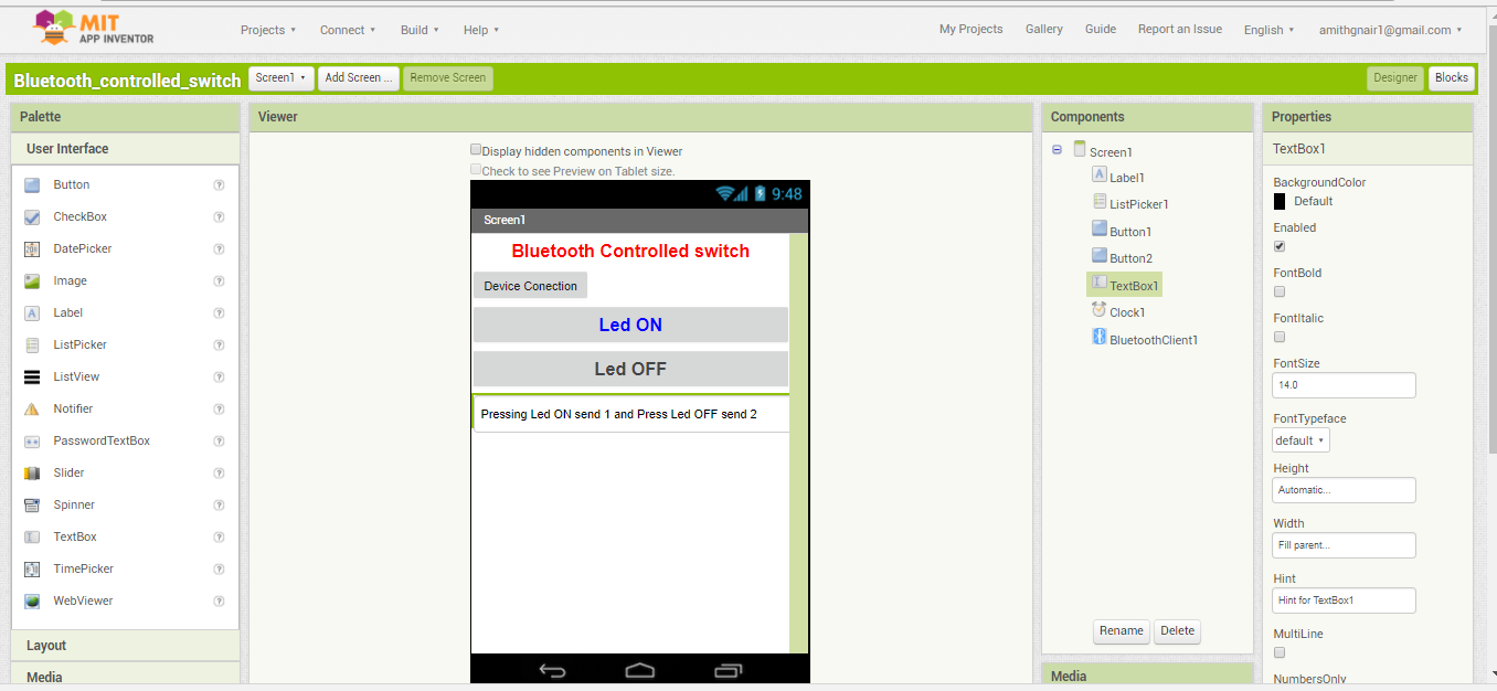
I used the label to create the title of my app and use Listpicker is used to list out the Bluetooth module addresses and names. After that, I add two buttons for On and OFF the Lamp. APP making logic is very straightforward means what you need pick and place.
After finishing the front view I go to Block editor stage, here in which we program the behaviour of APP. There are the different building block that helps as to do things like maths, text, logic etc.
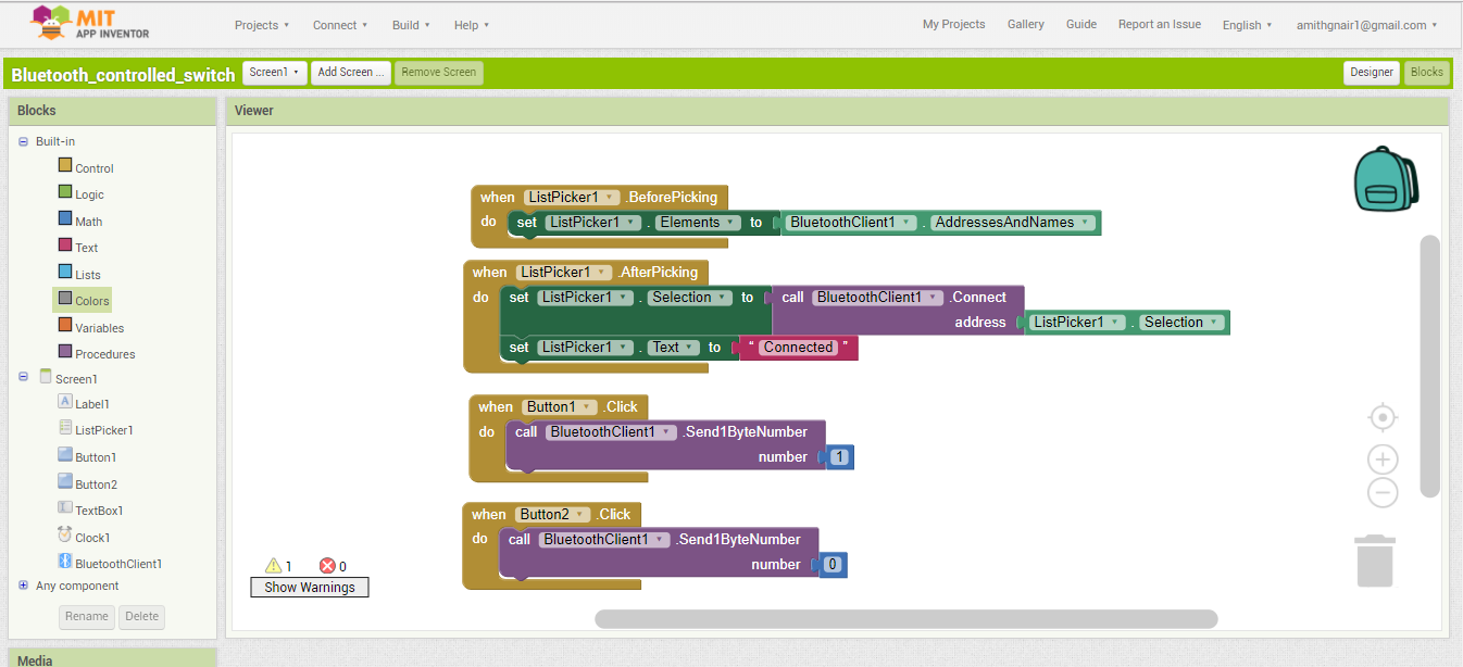
First block job is to list out the addresses and names of connected Bluetooth devices.
Second block job is when we select the Bluetooth. it establishes connection between selected device and application
First block job is to list out the addresses and names of connected Bluetooth devices.
// created by AMith G Nair : April 19 , 2018
#include <LiquidCrystal.h >  // call the LCD library
const int rs = 5, en = 6, d4 = 7, d5 = 8, d6 = 9, d7 = 10;  // intialization of pins of LCD module
LiquidCrystal lcd(rs, en, d4, d5, d6, d7);


const int ledPin = 4;      // the pin that the LED is attached to
byte serialA;
void setup()
{
 lcd.begin(16, 2);
 Serial.begin(9600);
 pinMode(ledPin, OUTPUT); // set led pin as output
}

void loop() {


  serialA = Serial.read();     // read the serial data
  switch (serialA) {
   case 1:       if one recives below statement executes
      lcd.clear();
      digitalWrite(ledPin, HIGH);  // make ledpin high
      lcd.setCursor(0, 1);   // set Cursor
      lcd.print("LED ON");   // LCD printing
     break;
   case 0:         // if recieve zero  below statement executes
      digitalWrite(ledPin, LOW);  // makes led pin low
      lcd.clear();
      lcd.setCursor(0, 1);// set Cursor
      lcd.print("LED OFF"); // LCD printing
     break;
 }
}
This code is very simple it checks if any serial connection is available and then read that variable. This variable is used for the condition checking .Here I connect a led on 13 pin already so if Serial data gets d value 1 its goes on and if value is 0 then led goes off.Code is uploaded using FAbISP made in electronic production week
After checking this its working perfectly , then I connect a relay box to control the lamp , relay box has three inputs VCC, GND and Control pin , control pin is used to On and Off the relay .I connect the relay box common pin to Phase wire from the plug and Normally opened pin to lamp and neutral pin connected directly from lamp holder to plug . Now I can control the lamp using bluetooth.I also connected the LCD dispon/ off it will print on that
After working with Bluetooth, app inventor and my MCU board, I think to work with some other tools also. So I decided to go with python and joystick. I refer our instructor Yadhus page to make that.I choose to use the Attiny44 board that I made for input week. I decided to create GUI with car and car is moving depends on the joystick. Python programming language used for writing the GUI. For communication MCU connected with Joystick, I used the serial library. In my application, there is a green car .
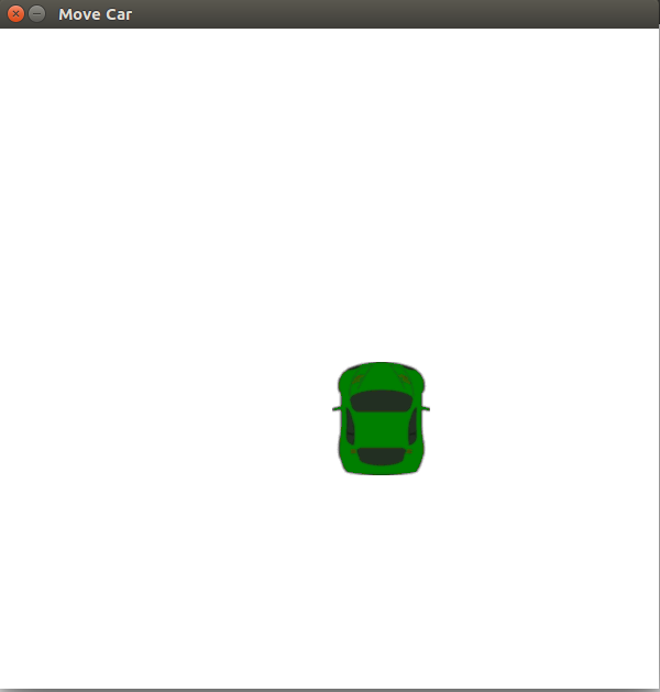
The movement of car depends on the direction of joystick.Micro controller reads the ADC value from joystick,here we have two ADC values X and Y depends on that they send some datas serially and GUI accepts that datas and move the car accordingly. For python codeing i refer this link .
Connection
Here i am using the same board that i made during the input week, Attiny44 - , That board cotain 10 bit adc, So i decided to use that for connecting it with Joystick
Joystick has 5 inputs VCC, GND,X axis,Y axis and switch. I connect VCC ,GND to the pins provide in MCU board and Also connect X axis and Y axis to A2 and A3 pins. Joystick consist of two potentiometer which measures the movement of stick in x and y axis. When we connect the x axis and y axis with MCU it send the analog values to MCU
Code:
Analog read function which reads the analog value, by default x and y gives a value of 512.when we moves x towards positive axis gives value upto 0 and negative axis gives a value upto 1023.Similarly for y also.
// created by amith G Nair: 23 April 2018

#include<SoftwareSerial.h> // Software serial library
SoftwareSerial serial(0, 1);
const int xPin = A3;  //declare th pins
const int yPin = A2;
void setup() {
  serial.begin(9600);
}

void loop() {
  int x = analogRead(xPin);   // read the sensors connected to analog pins
  int y = analogRead(yPin);   // read the sensors connected to analog pins
  if (x < 450 && y > 500  && y < 550 )  // cecking conditions
  { serial.print("R");

  }
  else if (x > 600 && y > 500  && y < 550 )
  { serial.print("L");

  }
  else if (y < 400 && x > 500 && x < 550)
  { serial.print("F");

  }
  else if (y > 550 && x > 500 && x < 550)
  { serial.print("B");

  }
  else if (x > 500 && x < 550 && y > 500  && y < 550)
  {serial.print("S");

  }delay(100);
}
So my aim is to move car forward when joystick moves forward, so I put some conditions inside the program when joystick moves forward it send a character of “F” and moves backward it send a character of “B” , moves Left it sends a character of “L” and moves right it sends a character of “R” .
After that I write the python script, that accepts the data coming through serially and depends on the data car moves forward and backward.
#Code is created by Amith G Nair : 23 April 2018
# refered the code of Yadhu Sharon : http://archive.fabacademy.org/archives/2016/fablabtrivandrum/students/384/week16.html
import sys, pygame, math
from pygame.locals import *
import time
import serial
a = serial.Serial(port='/dev/ttyUSB0',baudrate=9600,parity=serial.PARITY_ODD)   # open serial port

white   = (255, 255, 255)  # create the while colour array
black   = (  0,   0,   0)  # create the while colour array
width = 600                 # width of window
height = 600           #heigh of window
pygame.init()                        # initialize all imported pygame modules
clock = pygame.time.Clock()          # 	create an object to help track time
surface = pygame.display.set_mode((width, height)) # 	Initialize a window or screen for display
pygame.display.set_caption('Move Car')    # 	Set the current window caption
crashed = False
carImg = pygame.image.load('car.png')  # 	load new image from a file
def car(x,y):
    surface.blit(carImg, (x,y))
 x =  (width * 0.45)
y = (height * 0.8)
x_change = 0
car_speed = 0
FPS = 300
x=300
y=300
while not crashed:
    for event in pygame.event.get():          # get events from the queue
        if event.type == pygame.QUIT:
            crashed = True
    data=a.read()
    if data=='R':
    x+= 10
    elif data== 'L':
    x-= 10
    elif data=='F':
    y+= 10
    elif data== 'B':
    y-= 10
    surface.fill(white)  # fill the windows with white colour
    car(x,y)
    pygame.display.update()  # Update portions of the screen for software displays
    clock.tick(60)
After saving the python code I download a simple car image from online and reduce its size in gimp and save it as car.png.Then open the terminal and go to the folder where I saved python code and run the code by typing python joystick.py, it shows a window car I used the joystick to move that
Group assignment:
I worked with both python and MIT app inventor tools, others almost try with any of the two. After completing the individual assignment we sit together and discuss the tools we used, What we have done is we share our knowledge that we gain from this week.
In our lab all of them used At least MIT app inventor or Python to create the desktop or PC applications.
App inventor is just a block-based programming tool to create Android applications. It is just a starting programming language for beginners and not for advanced purpose. Python is typing programming language. It doesn't rely on blocks for programming; Python is a much harder programming language than App Inventor. Apps created using App Inventor can be downloaded to your Android phone or, if you don't have an Android, you can download an emulator from the website, but Python does not require the use of either an emulator or a phone.
Python Tkinter Vs game
Tkinter is one of the best GUI toolkits for Python and mostly it is used for utility applications. But pygame is used to create games and are not comparable. It all depends on the application you want to write. The choice of the right tool is usually something significant