Week 20:Project Developement
My project work started from June 6; I don't work for my project week before that day. From that time onwards need to do all the work and to complete it on June 16. Put the alarm on my phone and start my work.Smart phone is good for managing our work so it remind me every day about the presentation date.I refer online pages got details about how to measure voltage and current.3D designing is going on the other side. It's a different experience that I got after engineering graduation, before a couple of months back I only know something about electronics just but now I know how to fabricate our product digitally through various techniques.
Our last two weeks of Fabacademy we need to do a project that integrates the learnings that we acquired during this course, from starting onwards I have a plan to make a smart Plug that monitors the voltage and current and we can control it using the regular phone. I am still stuck with that idea. Measuring the voltage and current helps us to know about the power consumption,All of our houses have energy meters, and it only shows the entire energy consumption of the house. Using this device, you can monitor the power consumption of the individual device and also convert your existing equipment to IoT controlled device.
For doing this project, I referred various websites and got a lot of information from them for voltage and current measurement I got a lot of data from OpenEnergy monitor website and also Refer two Instructables tutorial for integrating telegram with Esp8266 mini Board Link 1 Link 2
My project can be divided into various parts :
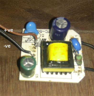
Part 1: Power supply: Here we need good and Noise free supply, so I used a small smps of 5v taken from the mobile charger. When we give 220v input, it returns with the voltage of 5v and current of 2A. For power supply i used a Small SMPS whih taken from moblie charger
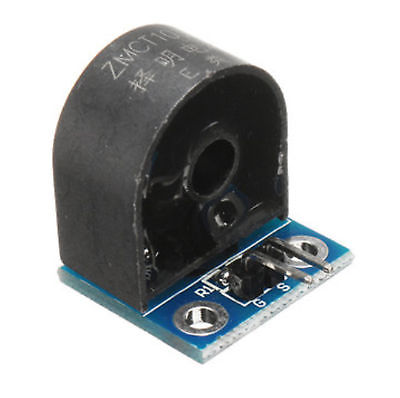
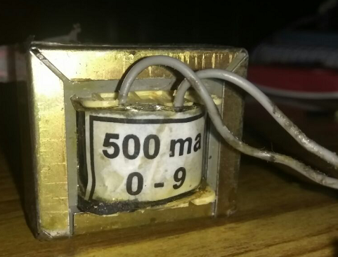
Part2: Potential Transformer and Current Transformer: For Measuring voltage I purchased a conventional step-down transformer of 220/9v and used a signal conditioning circuit to measure the voltage. For current measurement, cheap Chinese sensor ZMCT103c is used.
Part 3: MCU board that measures voltage and current, MCU board is equipped with atmega328p which measure voltage and current and send that data to Esp8266 mini Board through Rx and Tx pins
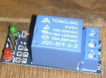
Part4: Relay and Esp8266 mini Board: is used to run the telegram control code which accept the sensor data from MCU board and establish connection with telegram and also controls the on/off operations utilizing the Relay , here in our lab only 12v relay exists so I purchased a 5v relay module and used with ESP8266 board
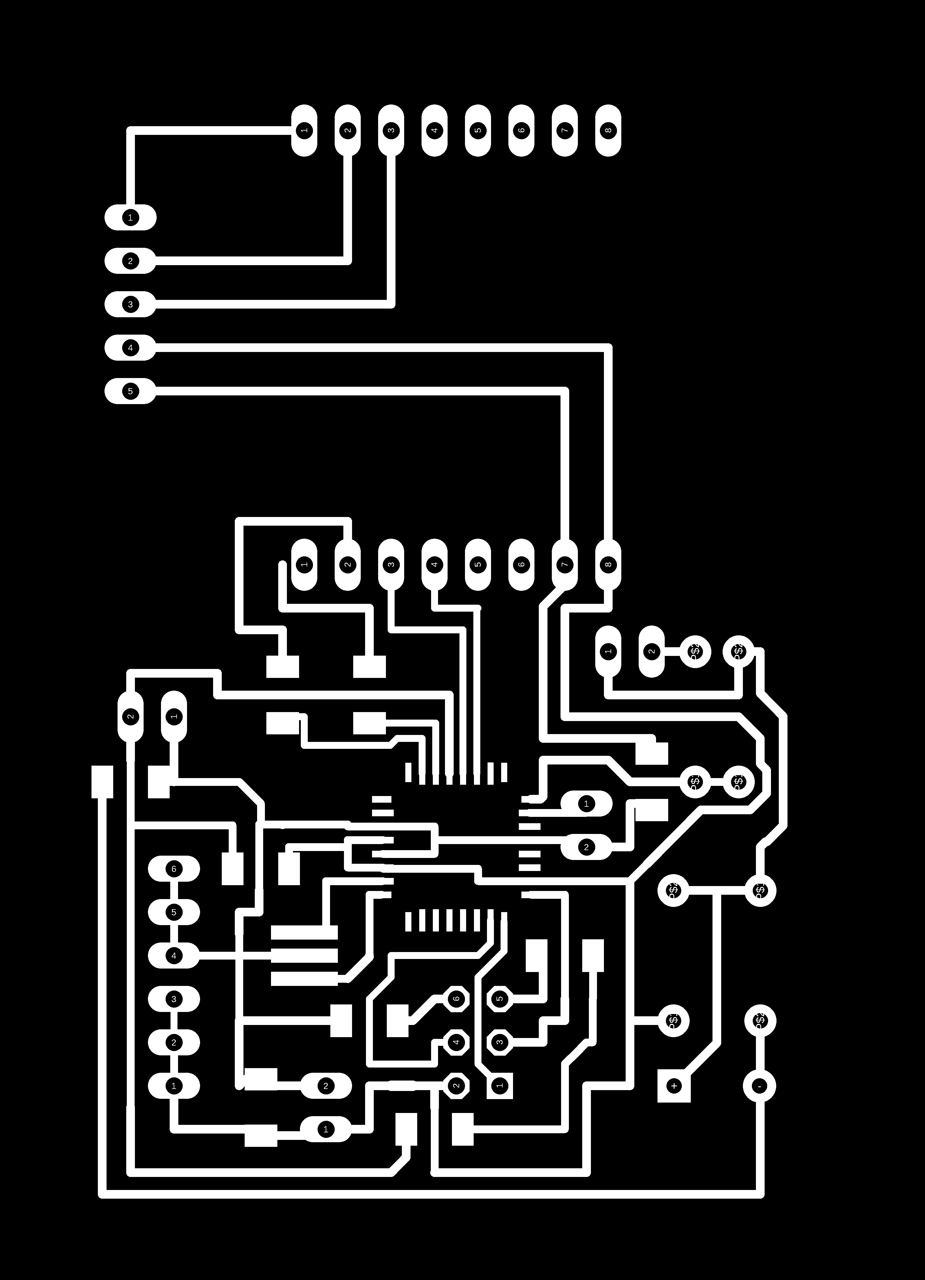
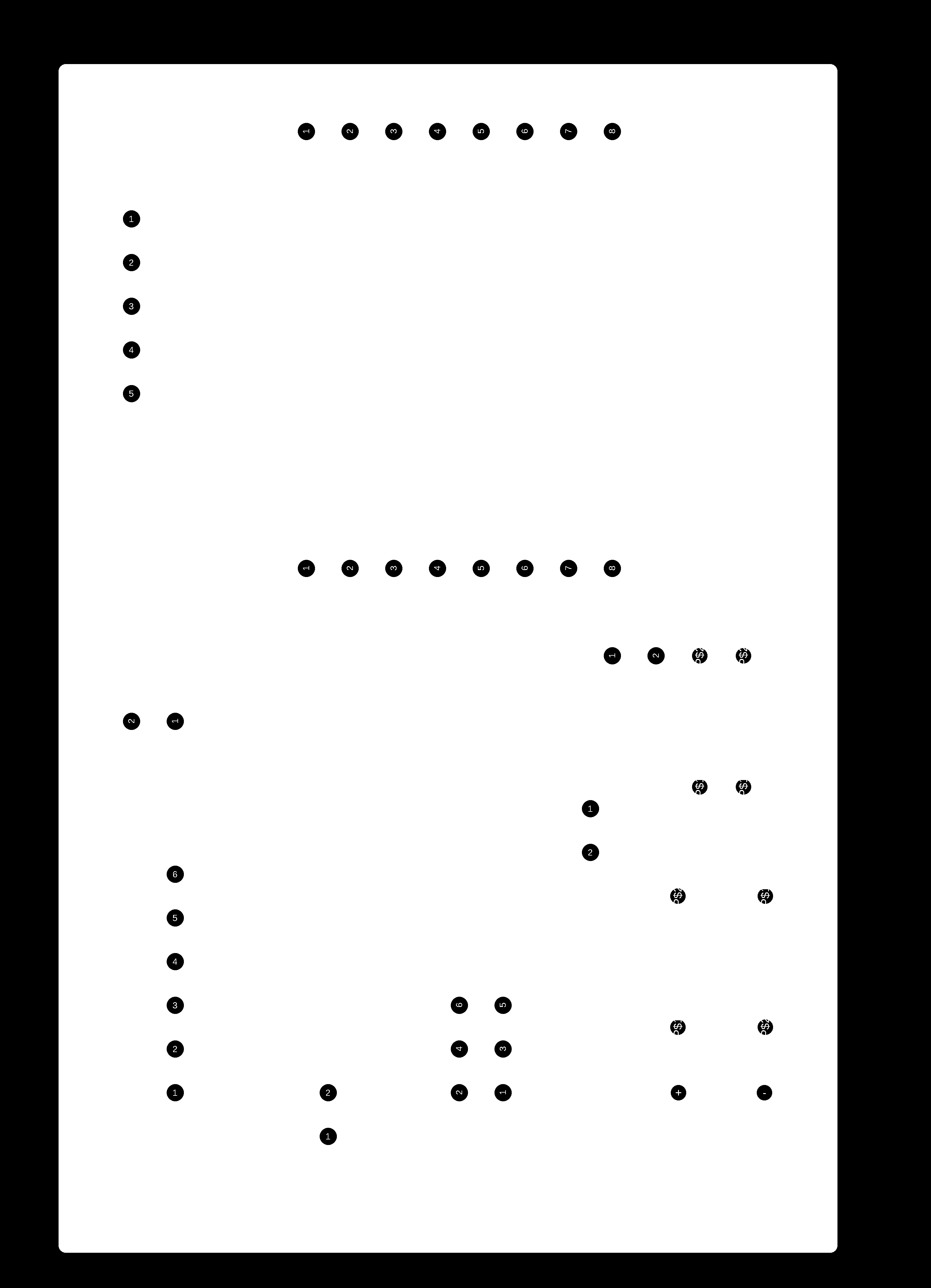
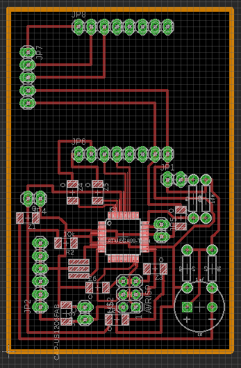
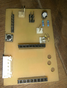
PCB design and Production :
Atmeag328p ic is used for making the Pcb; I am familiar with this on output week, so it's not a had part for designing the Pcb on the eagle.Atmega328p have eight analogue ports here I am using A0 and A1 for voltage and current.
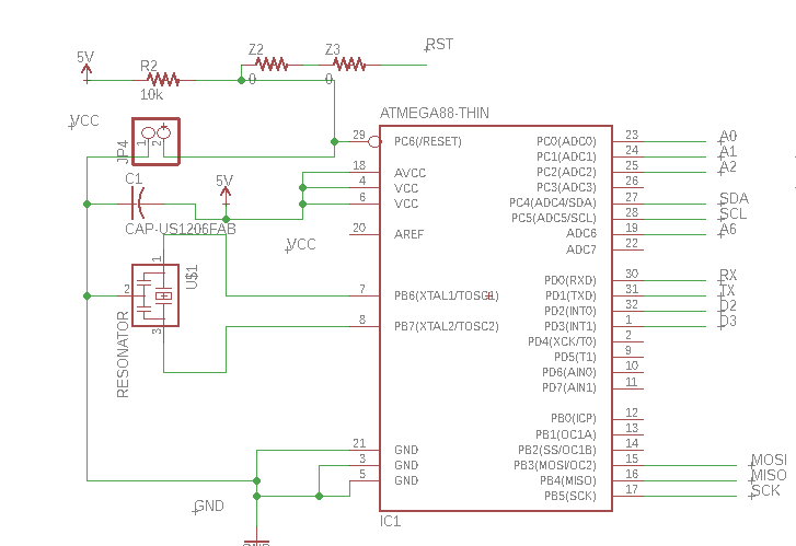
20Khz Resonator is connected across XTAL1, XTAL2 and ground Resonator is used to provide the clock to micro-controller. Clock is used to carry all the function that microcontroller provides.R resonator is a combination of both crystal oscillator and load capacitances connected to ground. Resonator consist of 3 legs which two connected to XTAL1, XTAL2 and centre leg is connected to GND.JP4 is for connecting press button switch , which is connected with reset and GND.Reset pin is pulled up by connecting 10k resistor seriously with VCC. Z2 and Z3 are zero resistors in order to avioid jumber wires while connecting reset pin of isp header.A1 connected with signal conditioning circuit which is connected with potential transformer.A0 is connected with ZMCT103 Current transformer directly.Rx and TX pins are connected with headers for Connecting Esp8266 mini board Also i2C connection is also establish between them.MOSI,MISO and SCK are provided for connecting it with ISP header.
Signal Conditioning Circuit for Potential Transformer
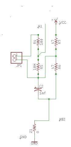
Signal conditioning electronics detailed below, is to condition the output of the AC power adapter, so it meets the requirements of the Atmega328p analog inputs: a positive voltage between 0V and the ADC reference voltage.O output of the step-down transformer is 9v, The signal conditioning electronics need to convert the output of the adapter to a waveform that has a positive peak that's less than 5V, So we need to:
- scale down the waveform
- add an offset, so there is no negative component.
The waveform can be scaled down using a voltage divider connected across the adapter's terminals, and the offset (bias) can be added using a voltage source created by another voltage divider connected across the power supply (in the same way we added a bias for the current sensing circuit).
Resistors R5 and R4 form a voltage divider that scales down the power adapter AC voltage. Resistors R6 and R7 provide the voltage bias. Capacitor C2 provides a low impedance path to ground for the AC signal. The value is not critical, between 1 μF and ten μF will be satisfactory. R5 and R4need to be chosen to give a peak-voltage-output of ~1V. For an AC-AC adapter with a 9V RMS output, a resistor combination of 10k for R5and 100k for R4 would be suitable:
The voltage bias provided by R3 and R4 should be half of the Arduino supply voltage. As such, R3 and R4 need to be of equal resistance. Higher resistance lowers energy consumption.
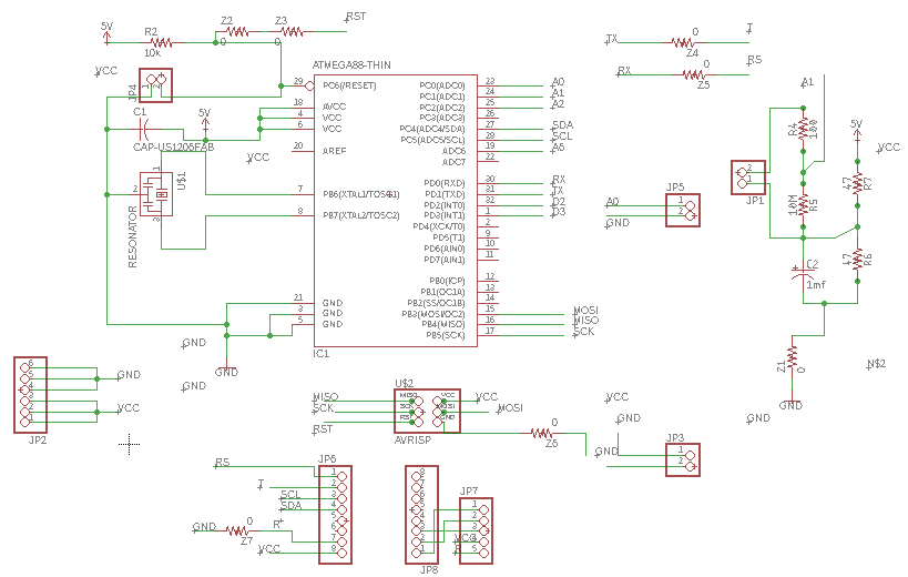
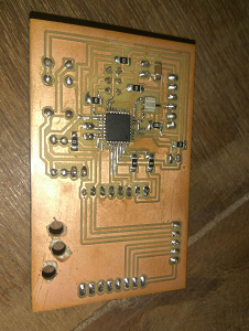
JP5 and JP6 header pins are provided for connecting esp8266 mini board with MCU board directly. Also offer VCC and GND directly, some extra supply is the need for working with the esp8266 board.JP2 are the additional VCC and GND pins.JP5 is provided to connect current sensor( Output of current sensor is two wires signal and GND, signally connected to Ao pin and other to GND of the board )Z4 and z5 are zero resistors used to avoid jumpers to connect with esp8266 Rx and Tx pins.After completion of PCB schematics next go with Board design, here i usd 18mm thickness as the width and 16mm as clearnce.It Takes 1 hours to route the enitre board.After that i export the PNG files for Milling the traces and also for cutting .
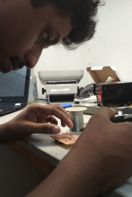
Completing the milling next, I go with soldering part. First I made a list of items I need and then I take it from the inventory list.
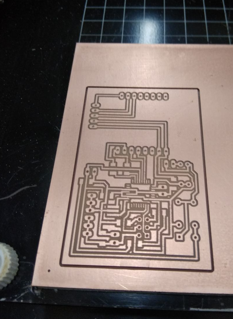
After completing the soldering process, I check it working with FABISP that I made in electronic production week. Next is the critical step I need to measure the voltage and current. Here I am using the ZMCT103C current transformer for measuring flow.
Embedded Programming
Current Measurement: I purchased a low-cost current transformer for Amazon website: ZMCT103C 5A Current Transformer with high accuracy, right consistency, for current and power measurement.5A AC Sensor requires two connections to from MCU board, and it needs you to run the wire that you wish to measure current on through the centre of the current transformer. How this sensor works is It measures the peak voltage dropped across the 200-ohm transistor that is on the transformer output and convert that voltage to current using ohms law I=V/R.
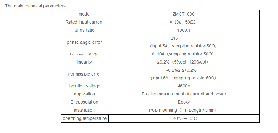
Details about CT is found from This source
Then multiplies the peak voltage by 0.707 to get and RMS Voltage across the resistor. (0.707 as a factor only applies to Sine Waves. It multiplies the RMS current by 1000 to get yield the value going through the wire being measured. (The current transformer has a 1000 to 1 ratio). Details are taken from this source ta12-100-arduino-ac-current-sensor-tutorial(Henry's Bench)
  /*
  http://www.chinalctech.com/index.php?_m=mod_product&_a=view&p_id=722
  http://henrysbench.capnfatz.com/henrys-bench/arduino-current-measurements/ta12-100-arduino-ac-current-sensor-tutorial/
  */
  // Henry's Bench TA-1200 AC Current Sensor Tutorial
  int sensorTA12 = A0; // Analog input pin that sensor is attached to
  float nVPP;   // Voltage measured across resistor
  float nCurrThruResistorPP; // Peak Current Measured Through Resistor
  float nCurrThruResistorRMS; // RMS current through Resistor
  float nCurrentThruWire;     // Actual RMS current in Wire
  void setup()
   {
     Serial.begin(9600);
     pinMode(sensorTA12, INPUT);
   }
    void loop()
   {
      nVPP = getVPP();  /*
     Use Ohms law to calculate current across resistor
     and express in mA   */
      nCurrThruResistorPP = (nVPP/200.0) * 1000.0;         /*
     Use Formula for SINE wave to convert   to RMS
     */
      nCurrThruResistorRMS = nCurrThruResistorPP * 0.707;
        /*
     Current Transformer Ratio is 1000:1...
        Therefore current through 200-ohm resistor
     is multiplied by 1000 to get input current
     */
       nCurrentThruWire = nCurrThruResistorRMS * 1000;
      Serial.print("Volts Peak : ");
     Serial.println(nVPP,3);
      Serial.print("Current Through Resistor (Peak) : ");
     Serial.print(nCurrThruResistorPP,3);
     Serial.println(" mA Peak to Peak");

     Serial.print("Current Through Resistor (RMS) : ");
     Serial.print(nCurrThruResistorRMS,3);
     Serial.println(" mA RMS");

     Serial.print("Current Through Wire : ");
     Serial.print(nCurrentThruWire,3);
     Serial.println(" mA RMS");
     Serial.println();
       }


   /************************************
  In order to calculate RMS current, we need to know
  the peak to peak voltage measured at the output across the
  200 Ohm Resistor

  The following function takes one second worth of samples
  and returns the peak value that is measured
   *************************************/


  float getVPP()
  {
    float result;
    int readValue;             //value read from the sensor
    int maxValue = 0;          // store max value here
     uint32_t start_time = millis();
     while((millis()-start_time) < 1000) //sample for 1 Sec
     {
         readValue = analogRead(sensorTA12);
         // see if you have a new maxValue
         if (readValue > maxValue)
         {
             /*record the maximum sensor value*/
             maxValue = readValue;
         }
     }
        // Convert the digital data to a voltage
     result = (maxValue * 5.0)/1024.0;
     return result;
   }
Voltage Measurement: For measuring voltage, I am using 220/9v transformer along with signal conditioning circuit. Details about the signal conditioning circuit are explained in schematic section.All the details are got from Open energy monitoring website The output from the transformer is 9v, and its scale down using voltage divider circuit and then that signal is offset using 2.5 voltage. So midpoint of the signal is shifted from 0 to 2.5v. Read the voltage at the analog pin and subtract it from 2.5 gives the instantaneous signal. This value converted back to the 220 scale.
For Measuring current Output pins of transfomer is connected to JP1 header pins : which is connected with signal conditioning circuit to MCU
Code for instantaneous voltage:
int float inst_filtered_voltage()
{

  int adc_voltage=analogRead(A1);
  long filtered_value=adc_voltage-511;    // convertion to actual value
  float inst_voltage=(filtered_value*5.0*input_transformer_voltage*11.46)/(1024.0*output_transformer_voltage); // 11.46 = (r1/r1+r2)
  return inst_voltage;
}
Code for calulating rms value:The root-mean-square is calculated in the way the name suggests first we square the quantity, then we calculate the mean and finally the square-root of the mean-square.
for (n=0; n<number_of_sample; n++){
   // inst_voltage calculation from raw ADC input goes here.
    squared_voltage = inst_voltage * inst_voltage;
    sum_squared_voltage += squared_voltage;
 }
 mean_square_voltage = sum_squared_voltage / number_of_samples;
 root_mean_square_voltage = sqrt(mean_square_voltage);
code for apparent:
apparent_power = root_mean_square_voltage * root_mean_square_current;
After measuring the voltage current, now I can also calculate the apparent power. Next part is communication; I need to communicate with esp8266 Mini board. I plan to send sensor data from Atmega328p board to Esp8266 using RX-TX or I2C communication . and Another code is running inside the esp8266 board to accept this data and perform chat action using the telegram.
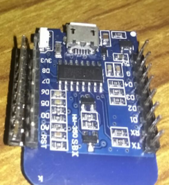
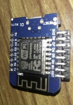
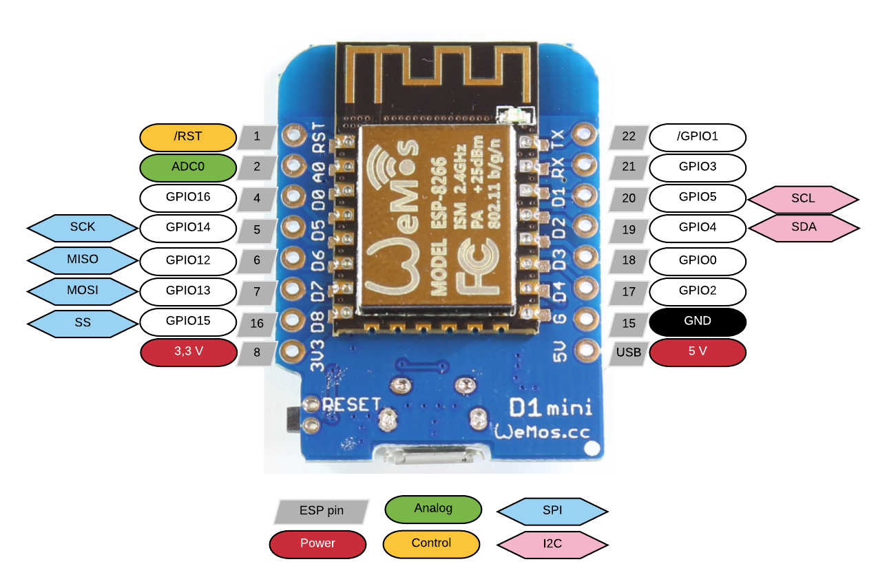
Esp8266: The ESP8266 is a low-cost Wi-Fi microchip with full TCP/IP stack and microcontroller capability produced by the Shanghai-based Chinese manufacturer. Here I am using ESP8266 MINI board. We can program this board using Arduino IDE. I am using a build in breakout board of esp8266; pin numbers are already marked in the board itself. I made the design by considering all the facts. But after soldering one side theesp8266 board not enter into penholder.The position of the pin holder increases to small, so I used 90-degree header pins to solve these.
Setting up IDE for programming ESP8266 :
- Firstly open the Arduino IDE: Go to files and click on the preference in the Arduino IDE
- copy the below code in the Additional board's Manager http://arduino.esp8266.com/stable/package_esp8266com_index.json .click OK to close the preference Tab.
- After completing the above steps, go to Tools and board, and then select board ManagerNavigate to esp8266 by esp8266 community and install the software for Arduino.
For controlling purpose, I connect a 5V relay to the ESP8266, ESP8266 Mini board has, 10 Digital pins and one analog pin.RX and TX pin connected to TX and RX of Atmega328p, Also SDA and SCL of Atmega328p( A4, A5) connected to D1 and D2( I2C pins of ESP8266 Mini). Also, take a separate connection JP7 for connecting Relay. D0 Pin is used to control the relay.
Relay is connected to JP7 , Do is th conroll pin provides to control the relay.Controlling elay is quite easy.Once we make relay control pin high ( Makes 5V ) it turns on and once make low( 0v it turns off) This can achieve through below codes
  void setup()
  {
   pinMode( D0,OUTPUT); // Set D0 pin as OUTPUT pin
 }
  void loop()
  {
   digitalWrite(D0,HIGH); // sets dgitial pin higher
   delay(2000);
   digitalWrite(D0,LOW); // sets dgitial pin higher
  }
I plan to send the data serially from Atemeag and Esp8266 receives this data and split it and store in different variables
AtmegaMCU-Serial Sending Data Code
 // datas given for testing
 //created by Amith G Nair : May 30 2018
 void setup() {
  Serial.begin(9600);
}
void loop() {

  delay(1000);
  float v = 230.46;
  float c = 2.4;
  float w = 12.6;
  String h = String(v);
  String i = String(c);
  String j = String(w);
  String payload = h;
  payload += ", "; payload += i; payload += ", ";
  payload += j;
  Serial.print(payload);
  Serial.println();

}
ESP8266-Reciver and Spliter Code
 // Test coe for Spliting
void setup(){
   Serial.begin(9600);
}
void loop(){
    delay(1000);
    String first  = Serial.readStringUntil(',');
    Serial.read(); //next character is comma, so skip it using this
    String second = Serial.readStringUntil(',');
    Serial.read();
    String third  = Serial.readStringUntil('\n');
    Serial.println(first);
    Serial.println(second);
    Serial.println(third);
}
When data send from Atmega328p is separated by comma and space, and In Esp8266 I wrote code to split data according to comma and store in some variable. The data is sent successfully So Buad rate used for sending data is 9600. Next, I went with ESP8266 And wrote chat action code by referring to the Universal bot library. Its also working.
Communicate with the telegram; we need to do some steps. First, we need to create a telegram bot. Contact with Botfather. Using /newsbot command Create new bot. Take his token. Give this token to Code and then we can able to communicate with the ESP8266 board, Using this we can control ESP from any part of the world through Telegram.
3D Modeling and Printing
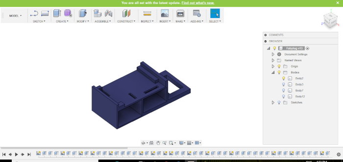
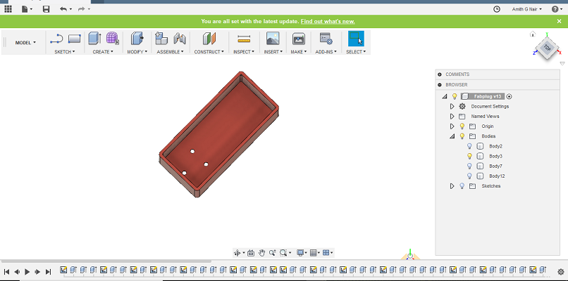
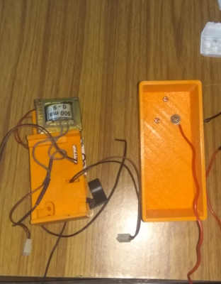
After that, I go with Designing the case I split the case into three. First, I design the Inner part to hold all the components. I need to Add a transformer, Relay box, ZMCT103 Current Sensor and stamps. I measure each parts using vernier calliper and draw the design according to that.
Initially, I plan to make the case using acrylic at that time Akhil made suggestion that goes with the robust design it makes your product a solid one. I decided to start with a small inner case to accommodate all the parts. First, I plan to give some space to hold the step-down transformer and give its position at the top and below that arrange SMPS. I bottom I put two holes to take out the input wires of SMPS. And then Relay and the Current sensor part. I made arrange them in parallel and built a small wall to separate it. Also made holes to taken wires to relay. Except Transformers other parts are in a closed structure
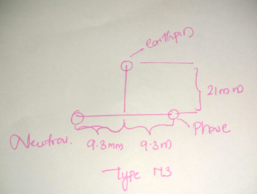
Desiging the plug and socket by refering this image
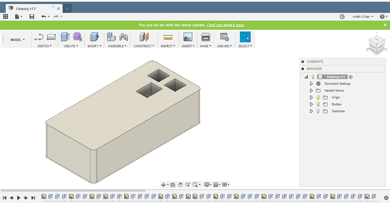
Completing the design, I go with the outer case, Every plug consists of two parts male and female. Male is used to connecting with power socket and female which we can connect devices. Next is the inner case and outer case. In bottom case, I need the plug ( male connection ) I already have the Metal parts of male, it can screw it so by referring the Type M diagram, I make three holes in the top ( 3 holes arranged in the form of the triangle) bottom case. Holes are creating by performing the extrude function. Male conectors are taken from an old plug available in my hand. Type M lug is normally used in India, so I consider the standards for designing the socket and Plug. More Details about Type M plug is from this source.
Designing case i need to consider plug and socket , we have 3 metal pins to connect with socket .Arrangement of three pins is in triangle format and Size of Earth pin is large compare to neutral and phase pins.
The final part is the female one, here in which same design Type M is adopted. The height of the inner case is around 35mm, and bottom case height is about 46mm SO we have extra 11 mm when we place the inner part on the bottom case. The maximum length of Earth pin is 20mm so we need socket of depth 20mm to accommodate the Male pins on that. So I consider the Top case of range 30mm. And 4mm Beech plywood on the top incorporates the total depth I need for the male pin.Inside that i can incoporate all the wires also.
After Completing the 3d Modeling I go with 3D printing, Here My model wall thickness is decidedly less only 2mm .So I give layer height of 0.1mm and fill density of 30 per cent and top and bottom layer thickness 1.2mm and Shell thickness of 1.2mm. I gave same settings for all the three parts.
Laser Cuting
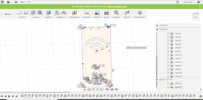
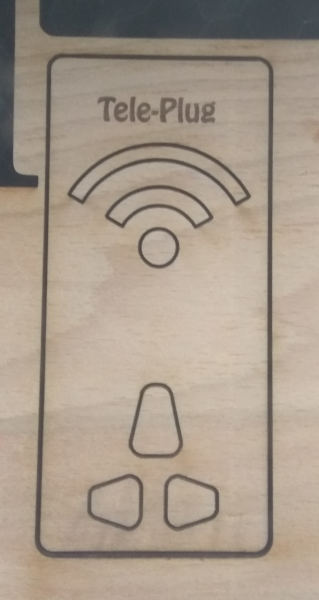
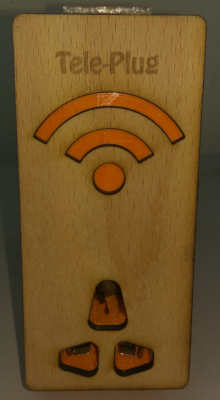
After that I go with laser cutting, I design the Front panel for the Model which the wifi symbol and name of the plug.I used Beech plywood for doing that; Setting are take from the Laser Cutting week
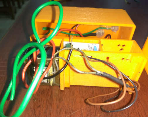
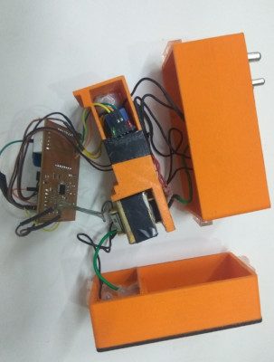
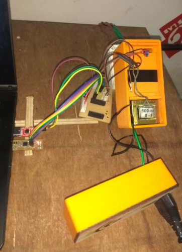
After completing all the works, I go with assembling. Its a most challenging part After Connecting the Plug pins ( It consists of Earth, Phase and Neutral ) From three pins I take three wires, Also connect the transformer input and power supply input to phase and neutral, and then I apply hot glue over that otherwise any short circuit occurs its dangerous, because device is working with AC .
Neutral and Earth wires taken directly to Socket connection Phase wire connected to the Common connection of Relay and from Normally Open connection I take the wire and passes through the CT and Connect to Phase point of Socket. After that, I upload the Energy Consumption monitoring code on MCU board and Telegram Action code on ESP8266. For MCU programming I am using the FAbISP i made During the Electronic production week .
After Assemble the device and connect a 40w bulb and control it using Telegram.Its working good.
Atmega328p -Code
// Code for measuring voltage and Current: Final Project
//Created on June 6, 2018
//Author Amith G Nair

float input_transformer_voltage=230.0;  //input voltage  pt meaured using voltmeter
float output_transformer_voltage=9.50;  // output voltage of pt meaured using voltmeter

int current_sensor = A0; // Analog input pin that sensor is attached to
float nVPP;   // Voltage measured across resistor
float nCurrThruResistorPP; // Peak Current Measured Through Resistor
float nCurrThruResistorRMS; // RMS current through Resistor
float nCurrentThruWire;     // Actual RMS current in Wire
float inst_filtered_voltage()
{

  int adc_voltage=analogRead(A1);
  long filtered_value=adc_voltage-511;
  float inst_voltage=(filtered_value*5.0*input_transformer_voltage*11.46)/(1024.0*output_transformer_voltage);
  return inst_voltage;
}
float rms_voltage()
{
  float sum_squared_voltage=0;
  for(int i=0;i&#;3000;i++)
  {
    float val=inst_filtered_voltage();
    float squared_voltage=val * val;
    sum_squared_voltage+=squared_voltage;
  }
  float mean_square_voltage = sum_squared_voltage / 3000.0;
  int rms_voltage = sqrt(mean_square_voltage);
  return rms_voltage;
}
void setup()
{
  Serial.begin(9600);

}
void loop()
{
  delay(1000);
  float voltage=rms_voltage();
  nVPP = getVPP();
  nCurrThruResistorPP = (nVPP/200.0)*1000;
  nCurrThruResistorRMS = nCurrThruResistorPP * 0.707;
  nCurrentThruWire = nCurrThruResistorRMS * 1000;
  float apparent_power =(voltage* nCurrentThruWire)/1000;
  String h = String(voltage);
  String i = String(nCurrentThruWire);
  String j = String(apparent_power);
  String payload = h;
  payload += ", "; payload += i; payload += ", ";
  payload += j;
  Serial.print(payload);
  Serial.println();
  delay(100);

 }

 float getVPP()
{
  float result;
  int readValue;             //value read from the sensor
  int maxValue = 0;          // store max value here
   uint32_t start_time = millis();
   while((millis()-start_time) < 1000) //sample for 1 Sec
   {
       readValue = analogRead(current_sensor);
       if (readValue > maxValue)
       {
           maxValue = readValue;
       }
   }
   result = (maxValue * 5.0)/1024.0;
   return result;
 }
ESP8266-Code
// Code for controlling Plug using telegram : Final Project
//Created on June 6, 2018,
//Some part of code is taken from Universal Telegram Bot library
//Author Amith G Nair
#include <ESP8266WiFi.h>
#include <WiFiClientSecure.h>
#include <UniversalTelegramBot.h>

char ssid[] = "test";                  // your network SSID (name)
char password[] = "*******";         // your network key
#define BOTtoken "########################"   // token from Telegram bot
WiFiClientSecure client;
UniversalTelegramBot bot(BOTtoken, client);
int Bot_mtbs = 1000;                //mean time between scan messages
long Bot_lasttime;                  //last time messages' scan has been done
bool Start = false;

void handleNewMessages(int numNewMessages)
{
  String volt  = Serial.readStringUntil(',');
  Serial.read(); //next character is comma, so skip it using this
  String current = Serial.readStringUntil(',');
  Serial.read();
  String watt  = Serial.readStringUntil('\n');  //read upto next line
  for (int i = 0; i < numNewMessages; i++) {
    String chat_id = String(bot.messages[i].chat_id);
    String text = bot.messages[i].text;
    String from_name = bot.messages[i].from_name;
    if (from_name == "") from_name = "Guest";
    if (text == "/Know_your_Supply_Voltage")
    {
      bot.sendChatAction(chat_id, "typing");
      delay(4000);
      bot.sendMessage(chat_id, volt);
    }
    if (text == "/Know_Device_Amphere_consumption")
    {
      bot.sendChatAction(chat_id, "typing");
      delay(4000);
      bot.sendMessage(chat_id, current);
    }
    if (text == "/Know_your_Device_Watt")
    {
      bot.sendChatAction(chat_id, "typing");
      delay(4000);
      bot.sendMessage(chat_id,watt);
    }
  if (text == "/OFF")
    {
      bot.sendChatAction(chat_id, "typing");
      delay(4000);
      digitalWrite(D0,HIGH);  // turns off the relay bydefault relay is on
      bot.sendMessage(chat_id,"Device is off");
      bot.sendMessage(chat_id,"/start : for more commands ");
    }
    if (text == "/start") {
      String welcome = "Welcome to SmartPlug, Telegram Bot is connected with your Device  " + from_name + ".\n";
      welcome += "This is Chat Action Based SmartPlug\n\n";
      welcome += "/Know_your_Supply_Voltage : send this  chat action message\n";
      welcome += "/Know_Device_Amphere_consumption : send this  chat action message\n";
      welcome += "/Know_your_Device_Watt  : send this  chat action message\n";
      welcome += "/OFF  : Do you want to control \n";
      bot.sendMessage(chat_id, welcome);
    }
  }
}
void setup() {
  Serial.begin(9600);
  pinMode(D0,OUTPUT);
  digitalWrite(D0,LOW);
  WiFi.mode(WIFI_STA);
  WiFi.disconnect();
  delay(100);
  WiFi.begin(ssid, password);
  while (WiFi.status() != WL_CONNECTED) {
    Serial.print(".");
    delay(500);
  }
}
void loop() {
  if (millis() > Bot_lasttime + Bot_mtbs)  {
    int numNewMessages = bot.getUpdates(bot.last_message_received + 1);
    while (numNewMessages) {
      Serial.println("got response");
      handleNewMessages(numNewMessages);
      numNewMessages = bot.getUpdates(bot.last_message_received + 1);
    }
    Bot_lasttime = millis();
  }
}
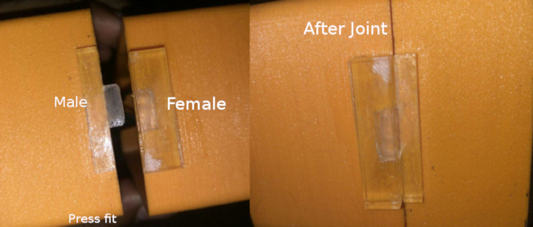
While desiging the outer case i forgot add joints to fix them together , so i decided to cut press fit, in which male joint attached to one case and female joint is attached to other , fix the press fit to model using some feviquick( adhesiv noramlly available in market to joint the plastics),
Controlling operations are performerd using Telegram , Fist we need to create the Telegram Bot, created telegram bot has token and its given to the token portion of code


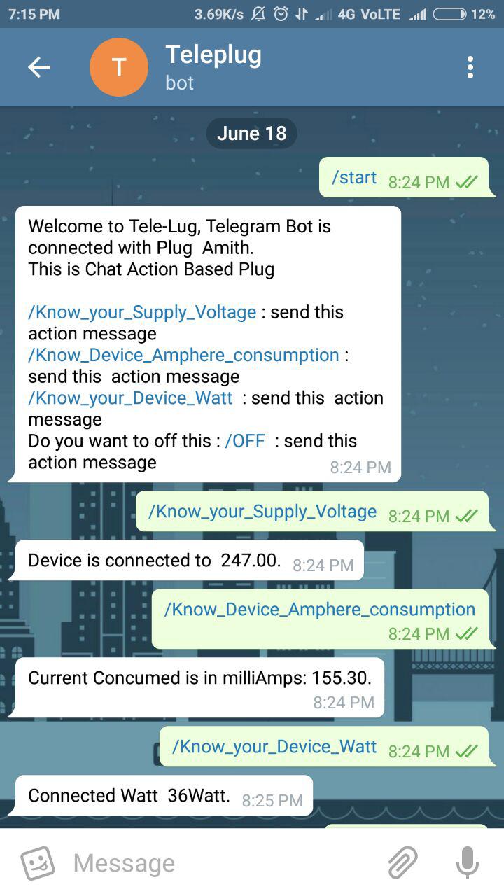
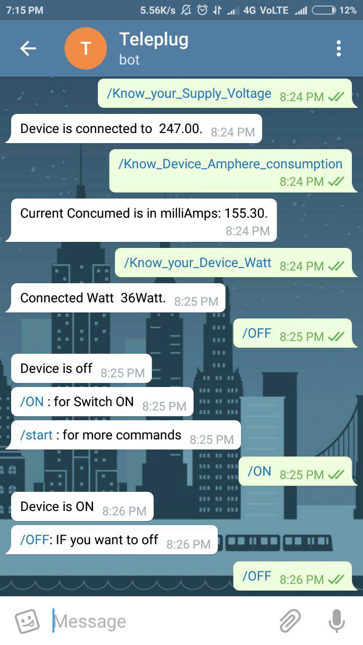
Above are the screen shots of telegram bot operated in My smart phone
For Details Refer Final Project page