Home
Week Twelve : Output Devices
Assignment
In this week, we had to add an output device to a microcontroller board we have designed, and program it to do something
We had a brief session on output devices from our instructors
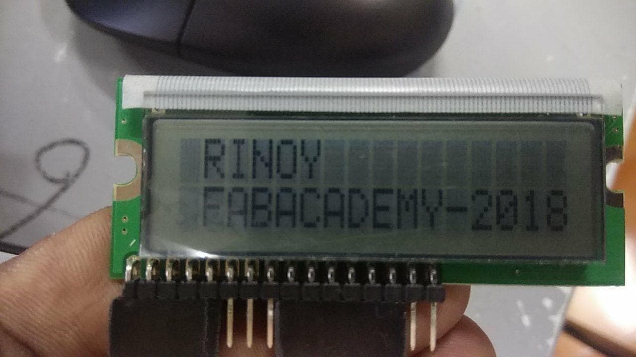
I have decided to use a LCD(Liquid-Crystal Display)
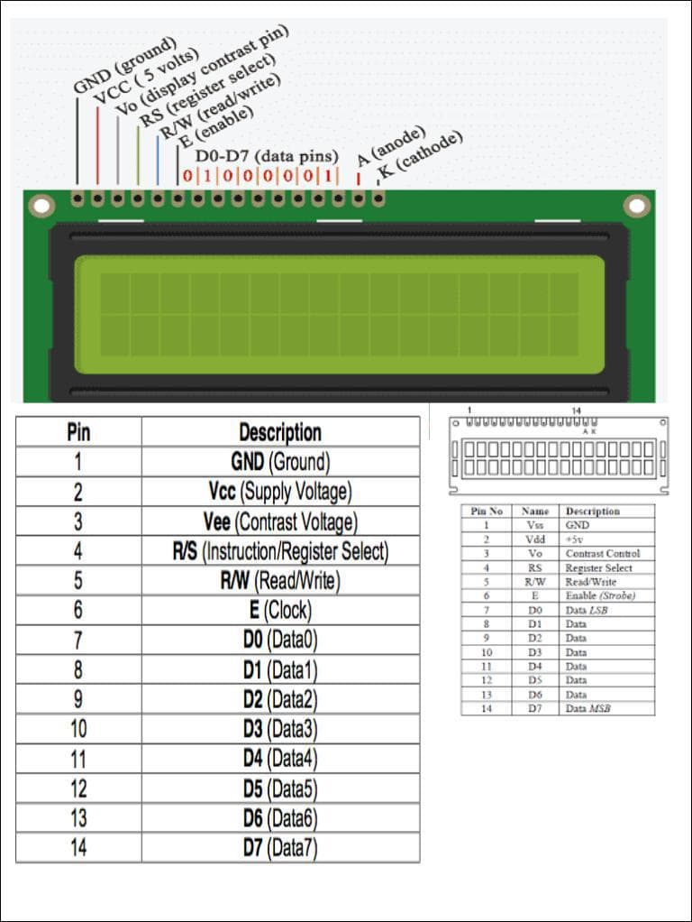
LCD is a flat panel display technology commonly used in TVs and computer monitors.
Liquid crystal displays are super-thin technology display screen.The backlight in liquid crystal display provides an even light source behind the screen. This light is polarized, meaning only half of the light shines through to the liquid crystal layer
DESIGNING
I have used EAGLE for designing PCB
I have downloaded libraries from Atmel and Fab directories. From those libraries I have added the components needed for my PCB
I chose Microcontroller - Attiny44 for this week
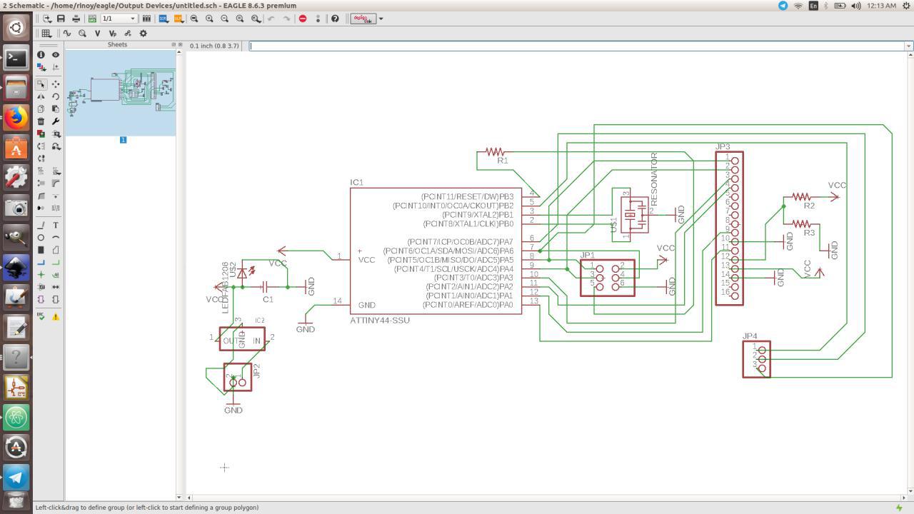
Schematic Representation
I have used Attiny44, ISP pinheader, FTDI pinheader, Resonator, Resistor and a Capacitor
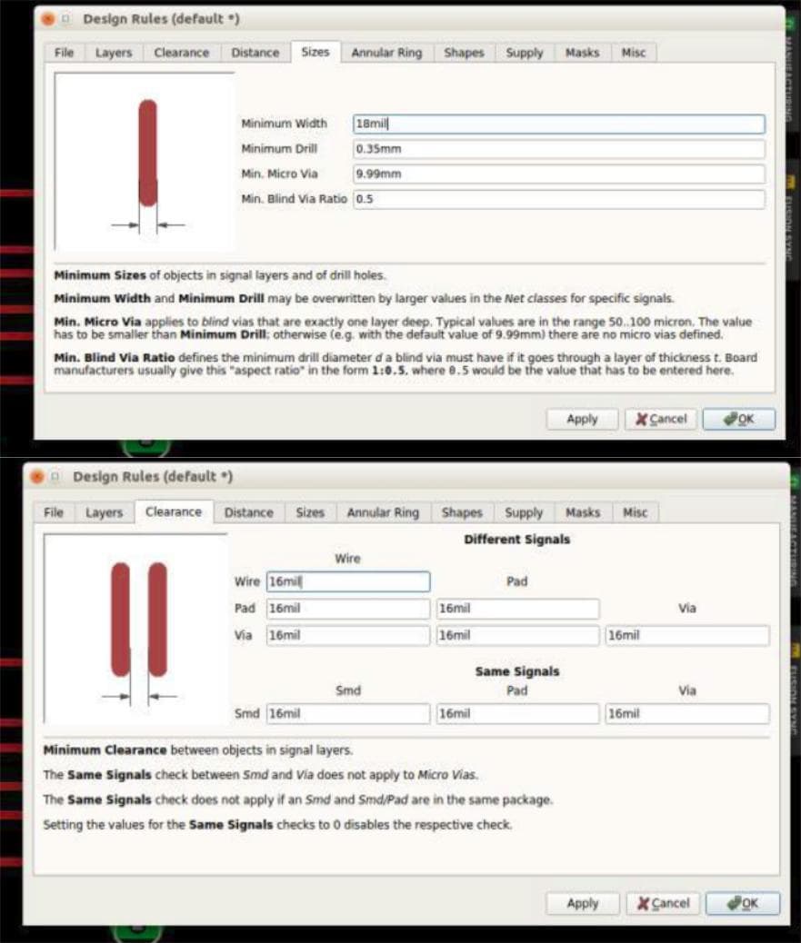
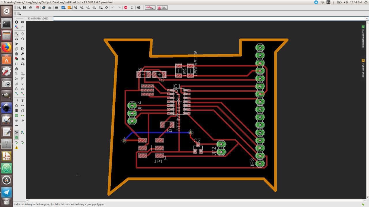
Switching to Board,Manual Arrangement and Setting Design Rules
Before Autorouting, I have set the rules for Clearance and Sizes to 16 mill and 18 mill respectively
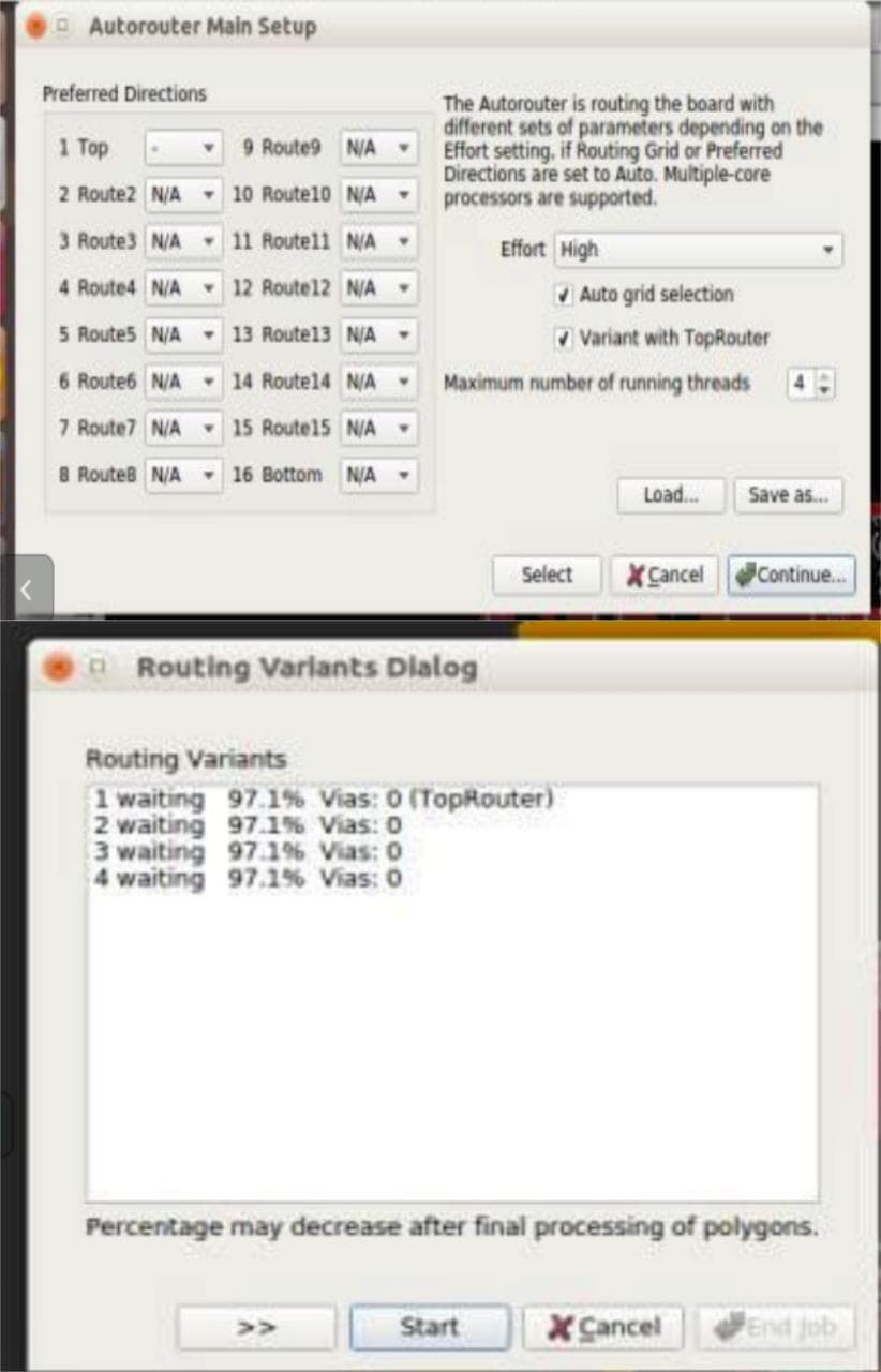
AutoRouting
Only half of the components got autorouted, so I have routed the other half manually using "ROUTE"
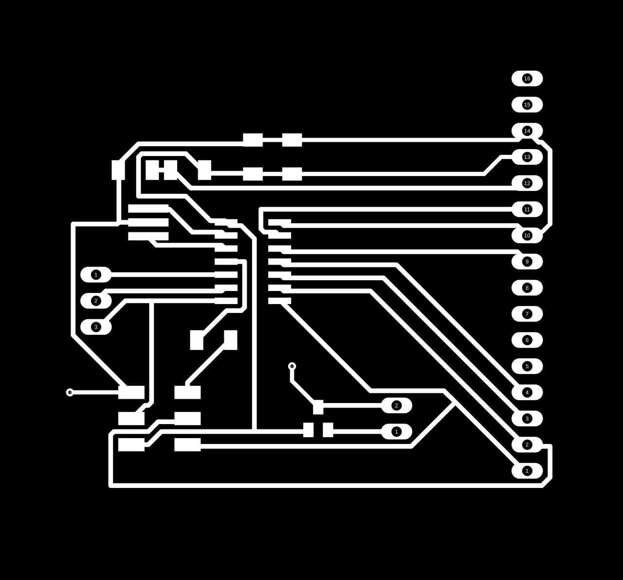
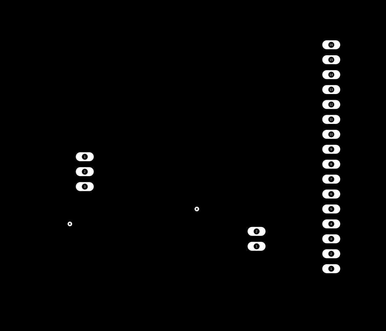
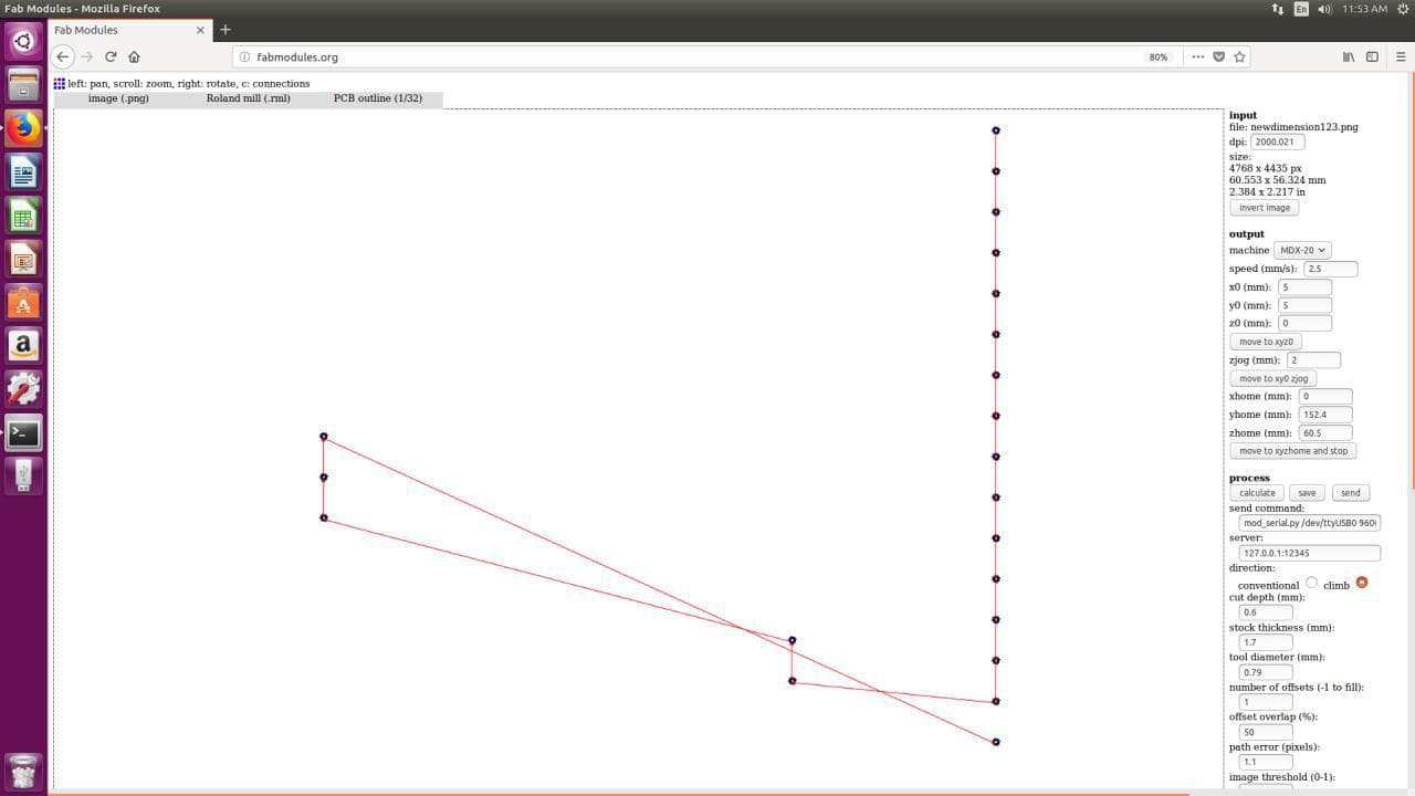
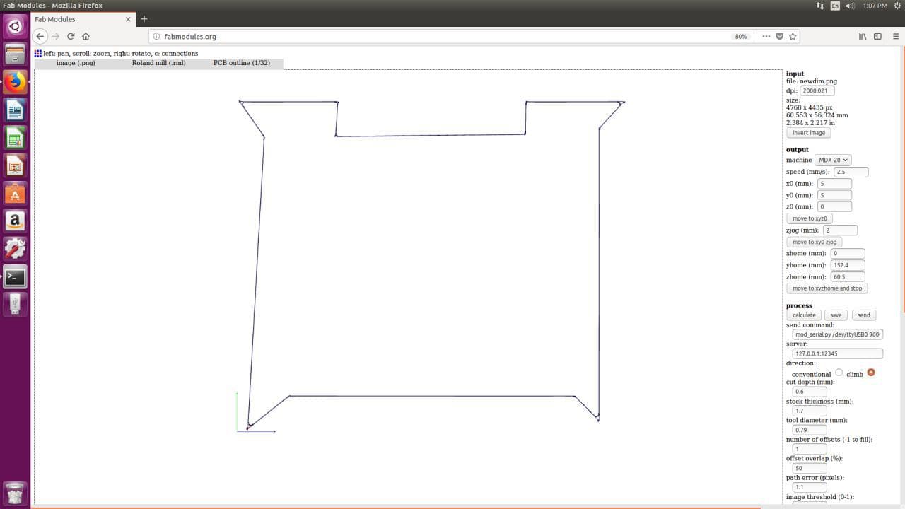
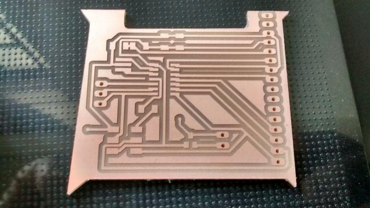
Saving Traces, Pads, Vias and Dimension
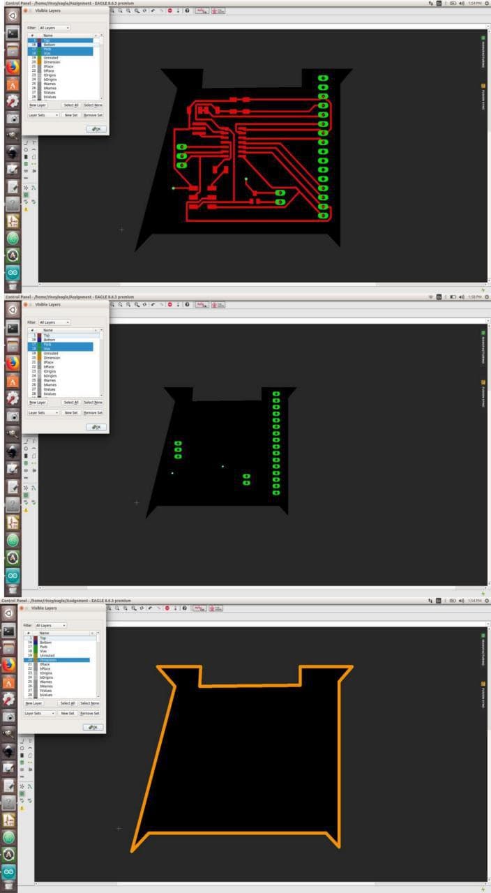
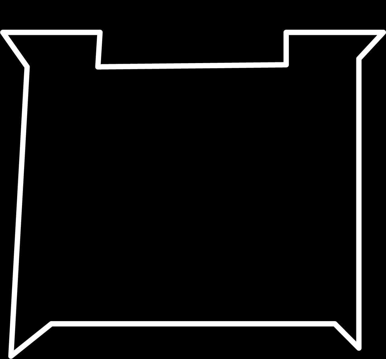
DESIGN
I decided to give a different shape for the border
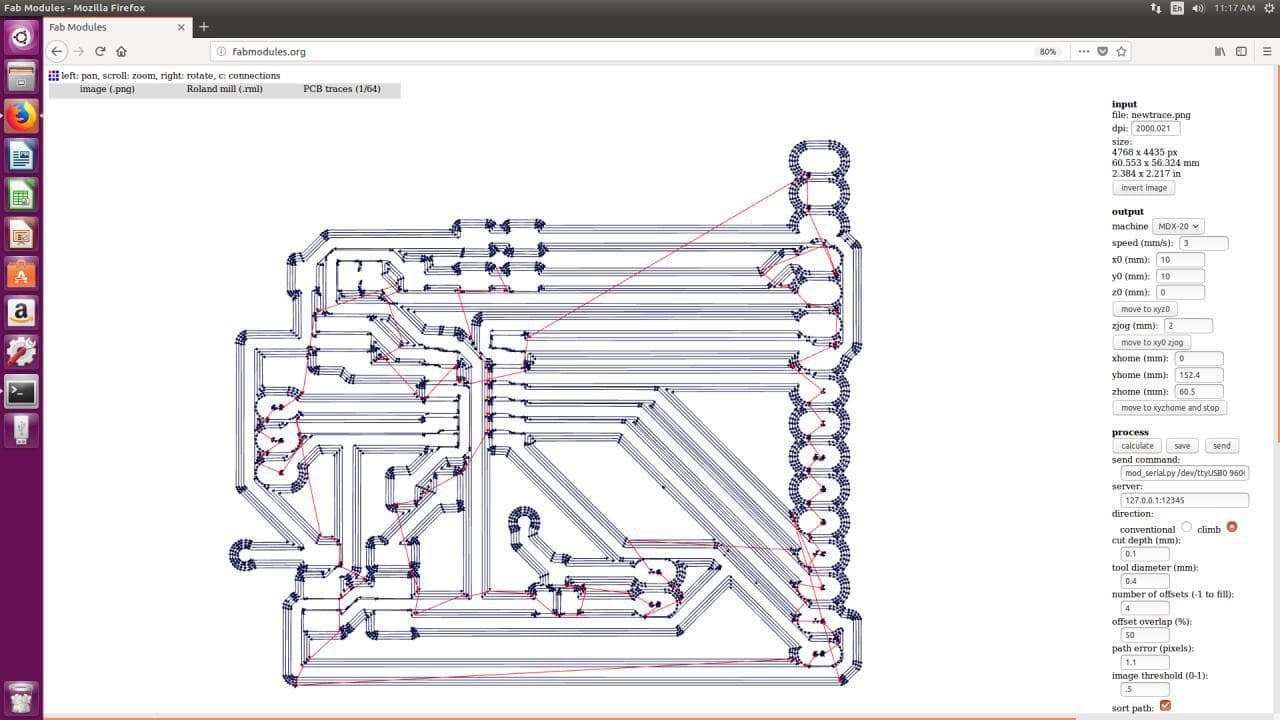
Traces for Milling
Settings on Milling Machine
Individual settings for Traces, Dimension and for Through-Holes
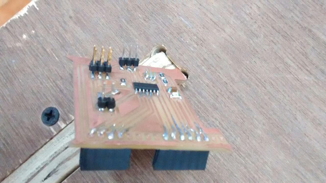
Milled ISP BOARD
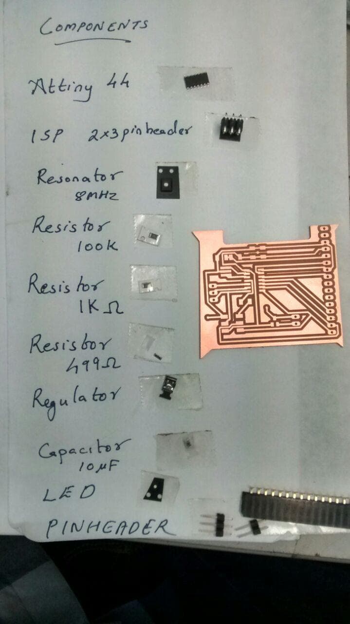
Components Used for my ISP Board
Microcontroller - Attiny44
Capacitor - 10 uF
Resistor - 499-Ohm
Resistor - 100 Kilo-Ohm
Resistor - 1 Kilo-Ohm
Resonator - 8 MHz SMD
FTDI - PinHeaders
ISP - 2*3 PinHeader
GPIO - General Purpose Input-Output Pins
Regulator - 5V,100mA
ISP BOARD
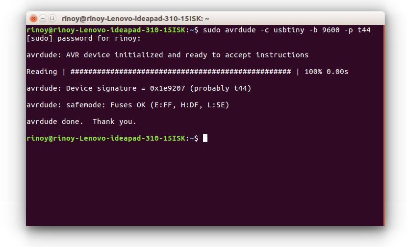
Checking the working of my ISP
sudo avrdude -c usbtiny -b 9600 -p t44
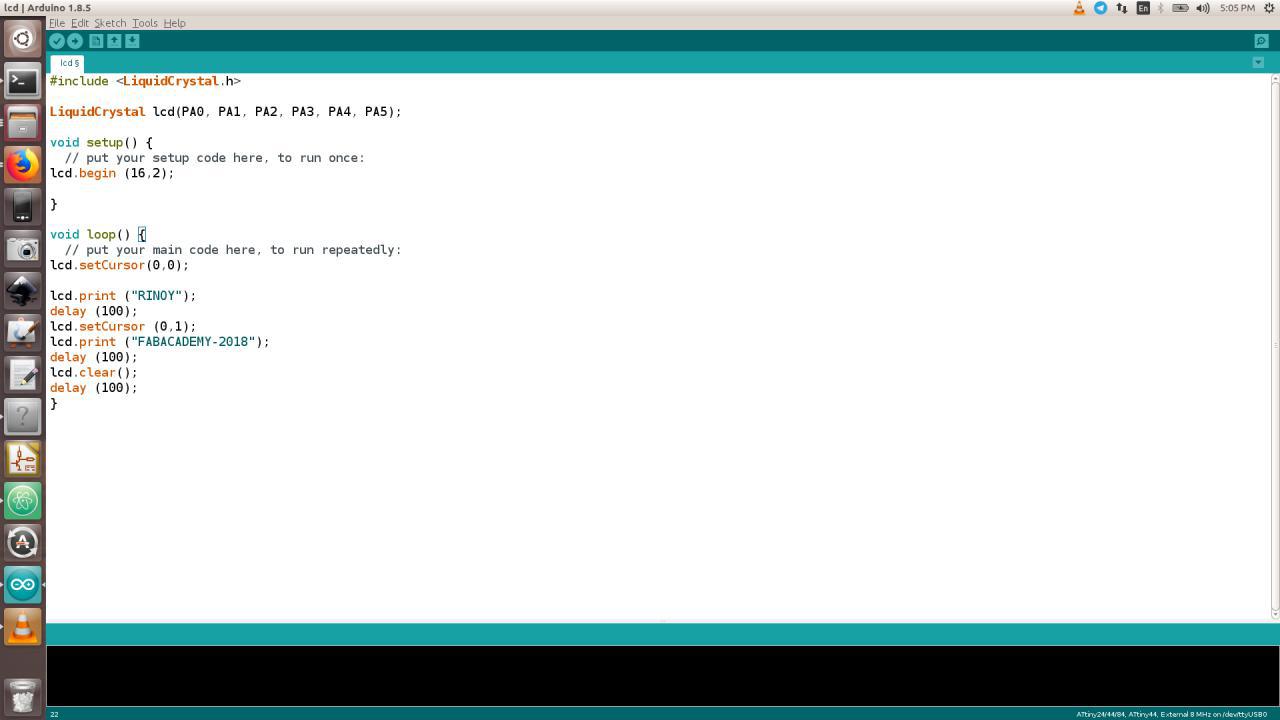
Program using Arduino
     #include

     LiquidCrystal lcd(PA0, PA1, PA2, PA3, PA4, PA5);

     void setup() {
       // put your setup code here, to run once:
     lcd.begin (16,2);

     }

     void loop() {
       // put your main code here, to run repeatedly:
     lcd.setCursor(0,0);

     lcd.print ("RINOY");
     delay (100);
     lcd.setCursor (0,1);
     lcd.print ("FABACADEMY-2018");
     delay (100);
     lcd.clear();
     delay (100);
 }
Video
Group Assignment
In this week, we had to Measure the power consumption of an output device
We choose a motor to do the same. Dc motors are not connected directly to microcontroller boards.We use Motor drivers to connect it with a microcontroller
Microprocessors operate at low voltages and require a small amount of current to operate while the motors require a relatively higher voltage and current. This current cannot supply to the motors from the microprocessor. This is the primary need for the motor driver IC
Here we are using L239D motor driver module to control small Dc motor.L239D motor driver is a small Current Amplifier whose function is to take a low-current control signal and then turn it into a higher-current signal that can drive a motor
Motor need large amount of energy, cheap and local motors it goes high
Voltage Requirement : Here we used motor is only run at voltage between 8v to 12 V
Current : Norammly L239D can supply current of 1.2A , so peak to peak become 3A something.if we need to give more current we need to provide heat sink over the driver IC