Home
Week Three : Computer-Aided Design
Designing
As well as website development, designing area is also first time for me. Our instructors Vinod and Lancy gave a wonderful session on designing 2D and 3D images. Professor Neil gave a brief session on vector and raster tool.Today (01/02/2018) i got a good view at these by our instructors.
Computer-aided design (CAD) is the use of computer systems to aid in the creation, modification, analysis, or optimization of a design
RASTER
A Raster image is made up of individual pixels
Raster-based image editors, such as Painter, Photoshop, Paint.NET, MS Paint, and GIMP, revolve around editing pixels.vector-based image editors, such as Xfig, CorelDRAW, Adobe Illustrator, or Inkscape, which revolve around editing lines and shapes.
From my understanding, Its more like a free hand drawing, which im not a fan of. I clearly have issues with drawing. Its definitely not my strong skills, but with the help of my instructors i hope i will be able to improve my skills in drawing.
Here is some tools i have tried this far.
1. GIMP (GNU Image Manipulation Program)
GIMP is a free and open-source raster graphics editor used for image retouching and editing, free-form drawing, resizing, cropping, photo-montages, converting between different image formats, and more specialized tasks
Brief idea from our instructors helped me to create an image which is shown below.
I have downloaded an image of Bulb, Water Splashing and Fishes from "Google"
Opened the Bulb image in GIMP
Rotated using "Rotate Tool" from tool menubar
Imported the Water Splashing image in GIMP
Scaled the image to fit in first image
Rotated using "Rotate Tool" to look like it splashing inside the bulb
"Multiply Tool" is used to join two images
"Add Layer Mask" from right click of layer, to erase unwanted water splashing overlapping the bulb
Used "Erase Tool", Zoom-in and erase the edges of watersplashing
Imported the Fishes image in GIMP
Scaled the image to fit in edited image
Moved the Fishes image and created a new Bulb Fish Tank

2. MyPaint
MyPaint is an easy-to-use painting program which works well with Wacom graphics tablets and other similar devices
A vector image is composed of paths, which are represented by mathematical functions. These mathematical function represents the actual borders and the different elements in the image
VECTOR
Vector-based image editors, such as Xfig, CorelDRAW, Adobe Illustrator, or Inkscape, which revolve around editing lines and shapes
Inkscape
Inkscape is a free and open-source vector graphics editor which can be used to create or edit vector graphics such as illustrations, diagrams, line arts, charts, logos.I installed Inkspace using the commands
First I had set width and height from File >> Document properties
Inkscape gave me a brief idea on setting path like Union & Difference
Learned to put a text on a path, as in office seal
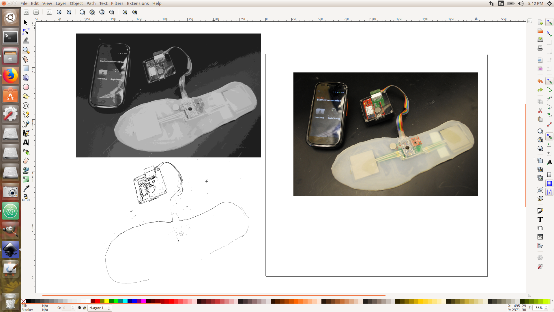
And I was excited to learn about a new feature(to me) which is TRACE BITMAP, which is shown below
2D and 3D Modelling
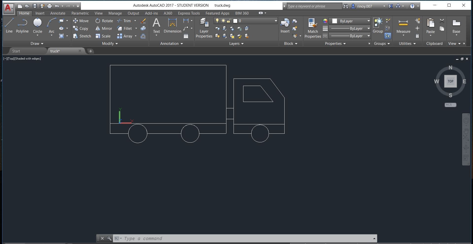
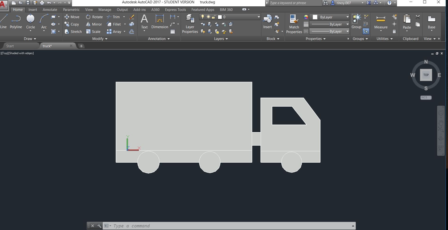
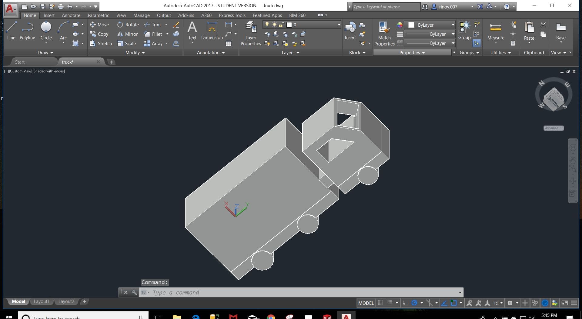
AutoCad
AutoCAD software is used for mechanical product design and drafting applications
I hope more of my experience is required to be documented other than the desription. Although AutoCad was necessary in my engineering academic year,i havent got a chance to know this software better. So I had a picture in my mind from childhood memories which is the only drawing i remembered.I figured that will be my first drawing afterall.
The main commands used are
Line: Draw the start point and end point of line
Circle: A center point, followed by diameter or radius
Arc: Create the start point, middle point and end point
Trim: Trim command is used to remove the unwanted edges
Extend: Used to extent a line
Subtract: Used to subract one surface from other
Region: Used to create a surface. A surface (XY plane) is a formed by a set of closed lines or arc
Extrude: Used to extrude a surface (in XY plane) towards Z axis
Other commands used are Mirror, Offset, Move, Array, Fillet, Subtract etc.
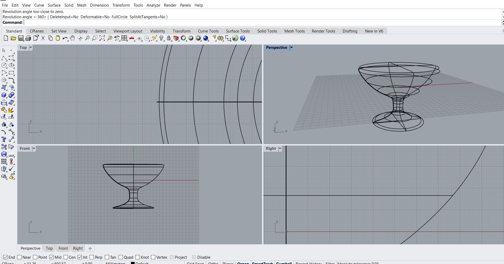
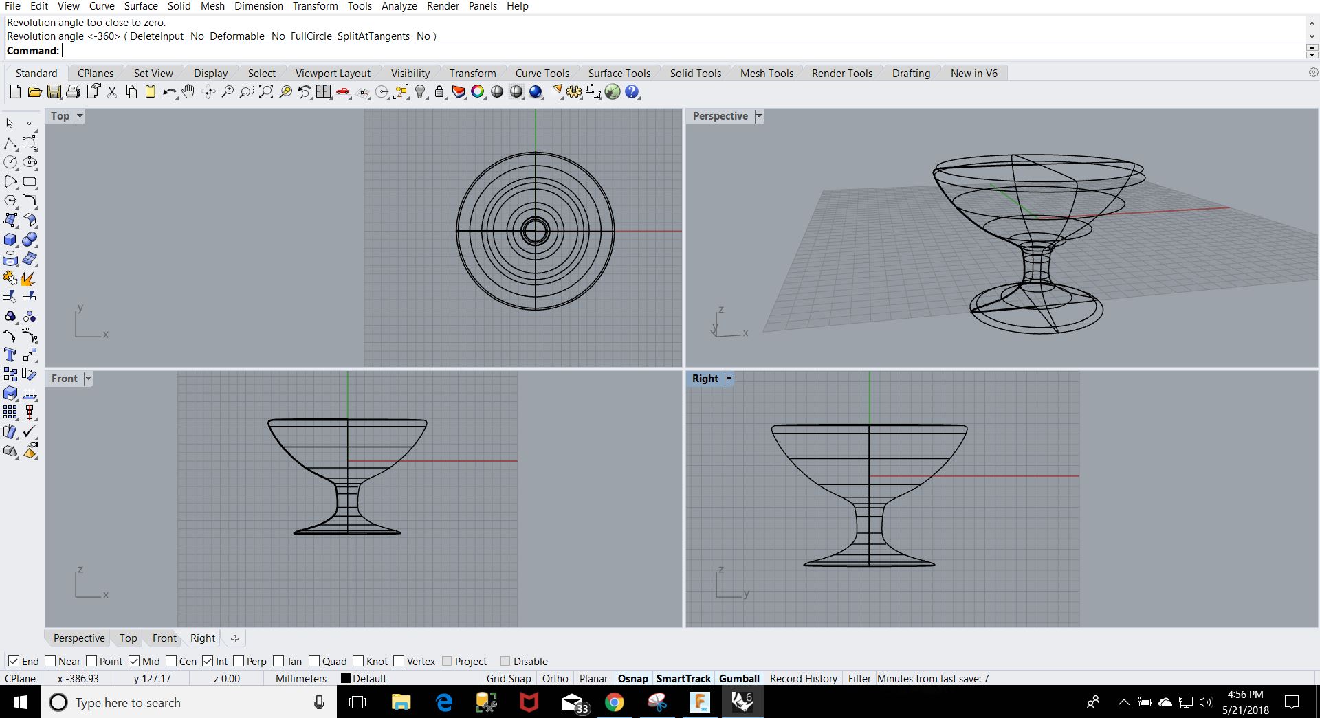
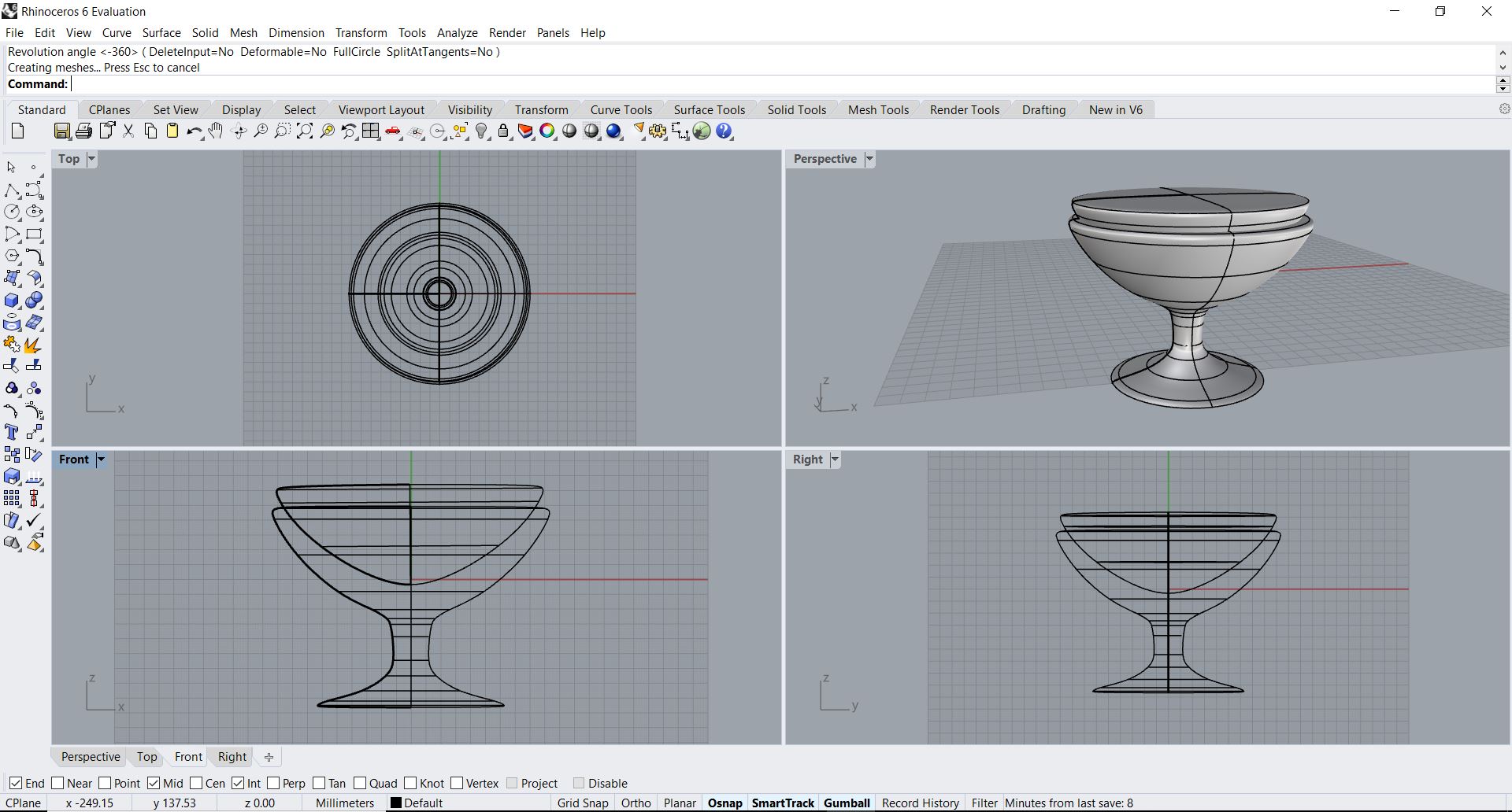
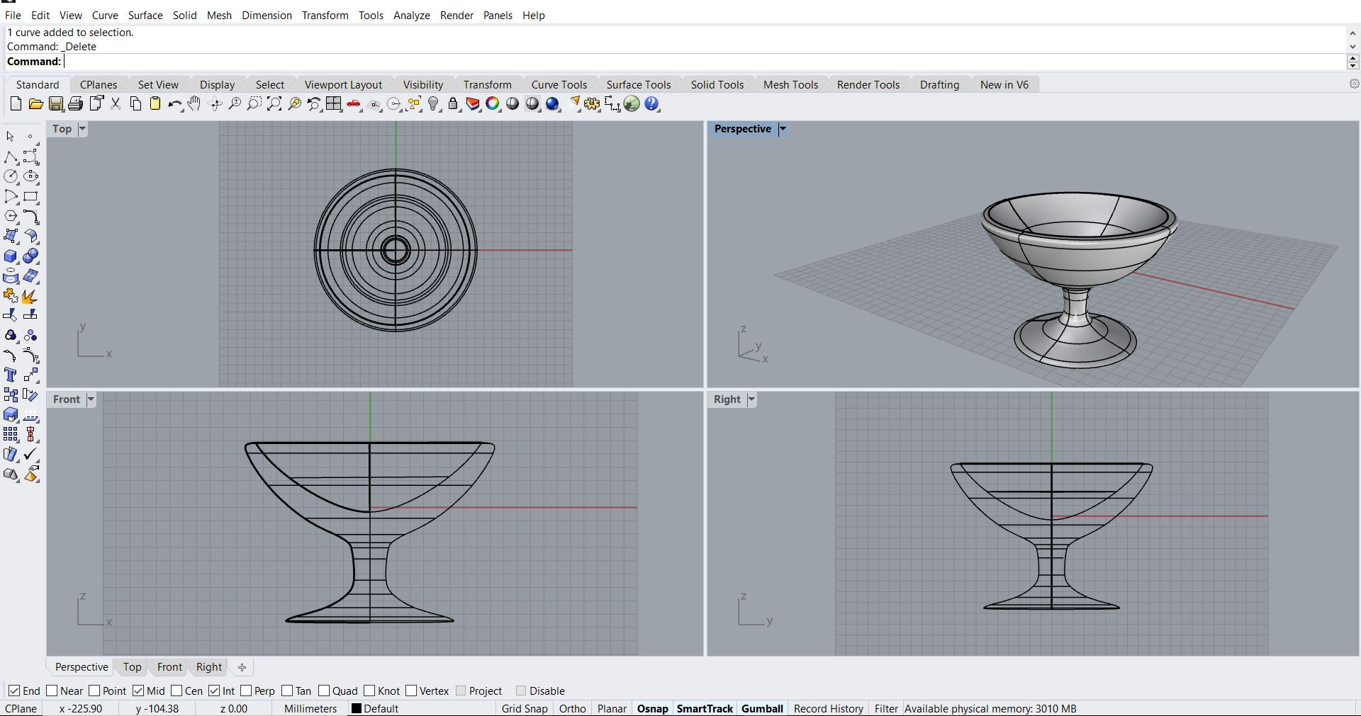
Rhinoceros
First time hearing about the software.I got a month licence for this software from Autodesk. Our instructor Vinod had given a great session on this, and seriously i got impressed with it. But also for drawing here, first you need to see things more creatively. You can draw it front, top and side view and also in 3D.
Rhino has 4 views - Top view, Perspective view, Front view and Right view
Also we are able to draw in every view
Osnap : Set object snaps state
Line : Draw multiple adjoining line segments
Offset : Copy a curve parallel to the original
Extrude : Make 2D image to 3D
Cap : Make hollow to solid image
Boolean Difference : To make a inside surface
Chamfer : Create a line segment between two curves and trims or extend the curves to meet it
Fillet : Adds an arc between two curves and trims the curves to the arc
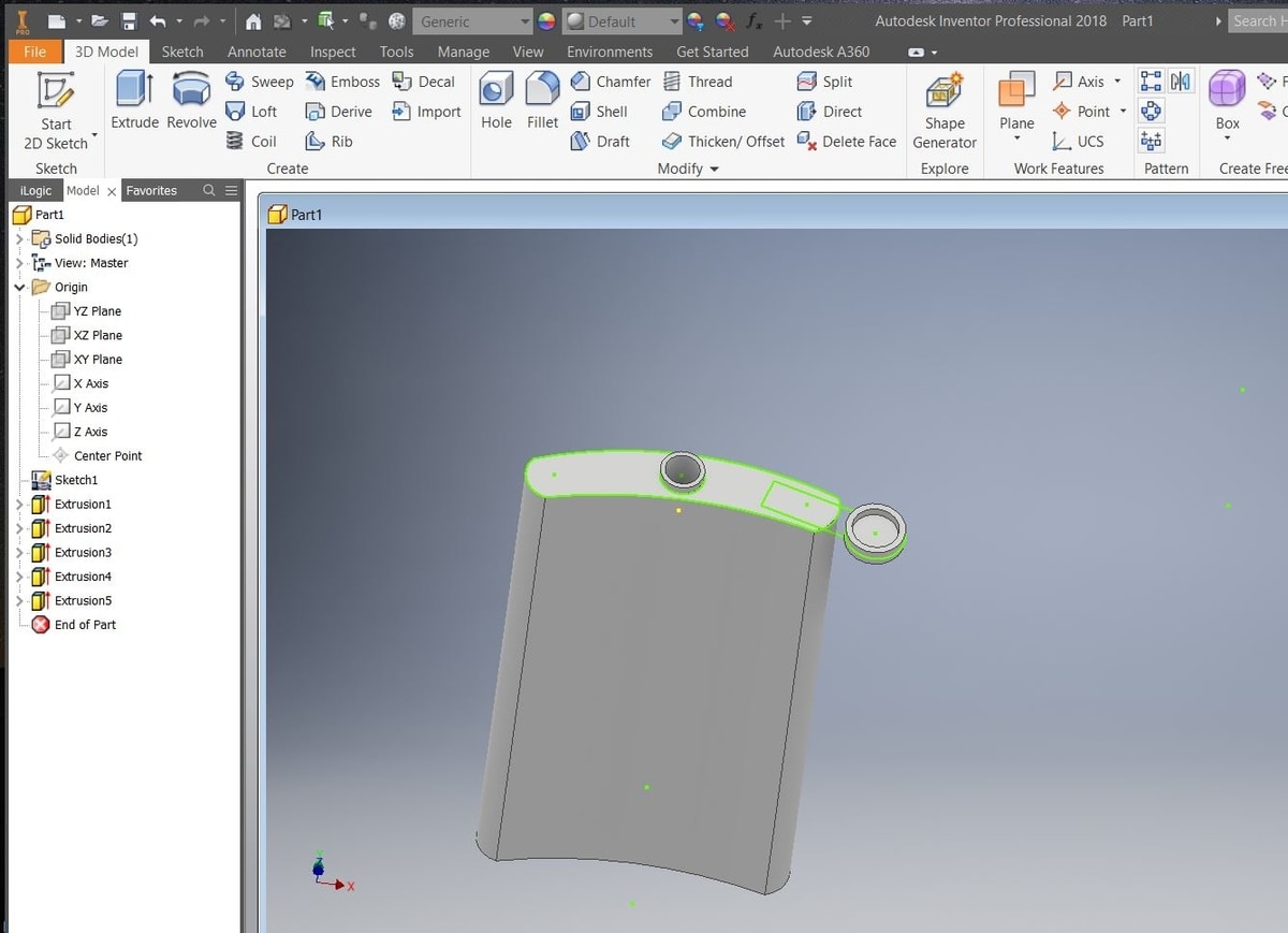
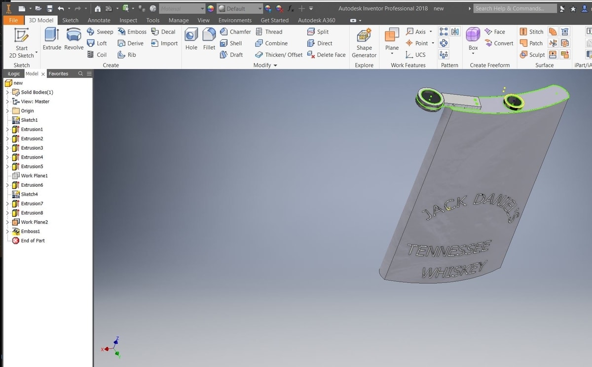
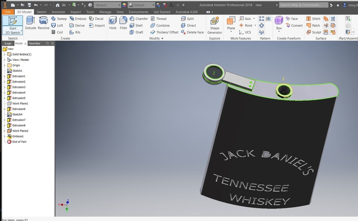
Inventor
First time using Inventor.I got a month licence for this software from Autodesk. Our instructor Lancy had given a brief idea about Inventor. I find it more user friendly.
Line: Draw the start point and end point of line
Circle: A center point, followed by diameter or radius
3 point Arc: Create the start point, middle point and end point
Trim: Trim command is used to remove the unwanted edges
Extend: Used to extent a line
Extrude : Make 2D image to 3D
Extrude in opposite direction : Make a hole of inside surface in 3D image
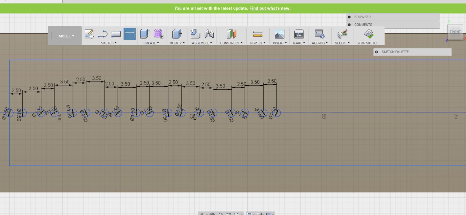
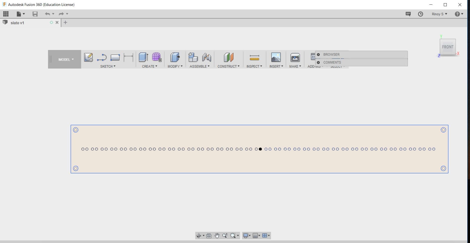
Fusion 360
Fusion 360 was learned at the time of Computer-Controlled Cutting(laser cutting).I was not able to get parameters comfortably in inventor,So i turned myself to new software with a help of my instructor and one of my friend.
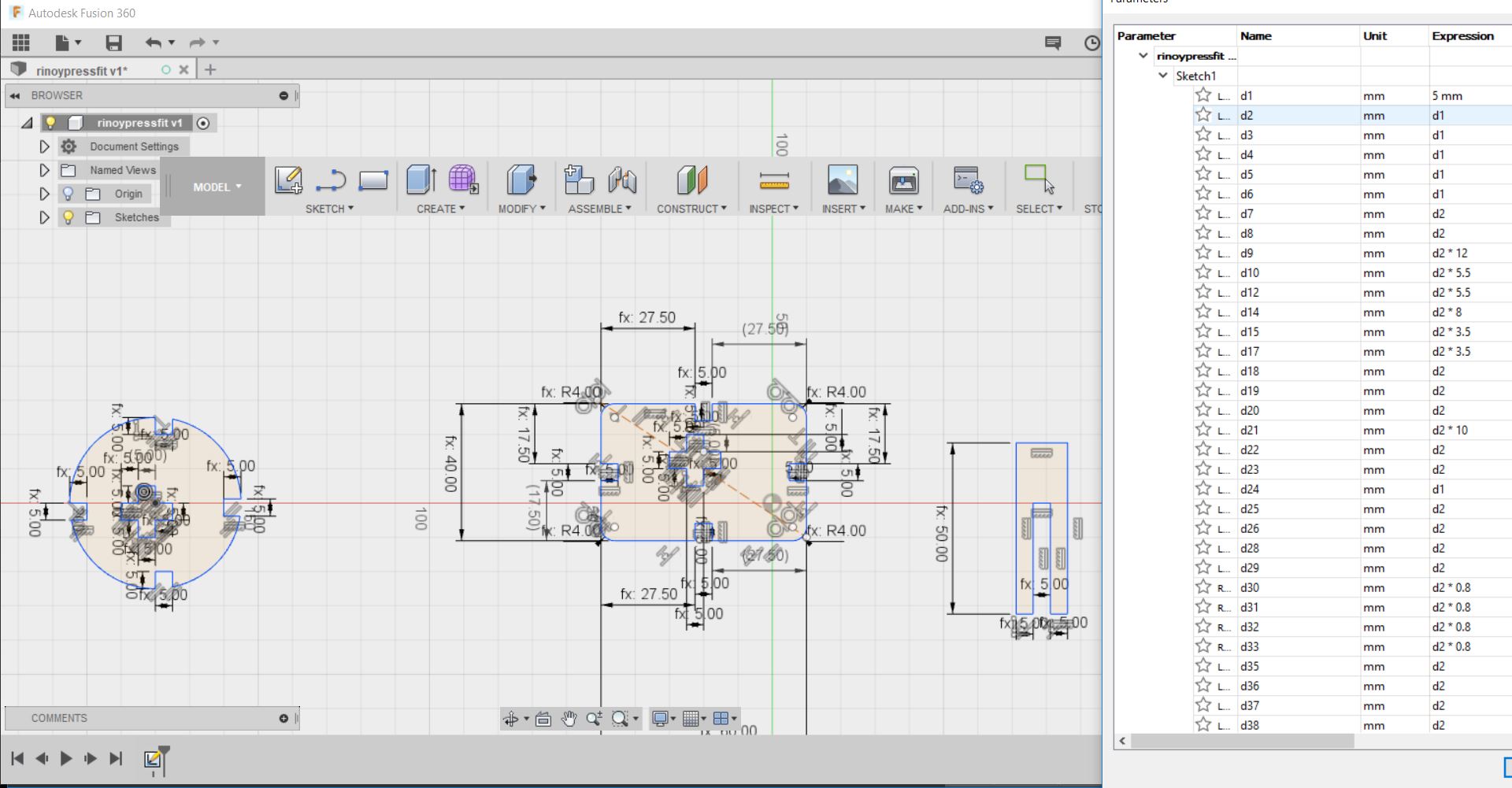
Also used to design during the time for shopbot
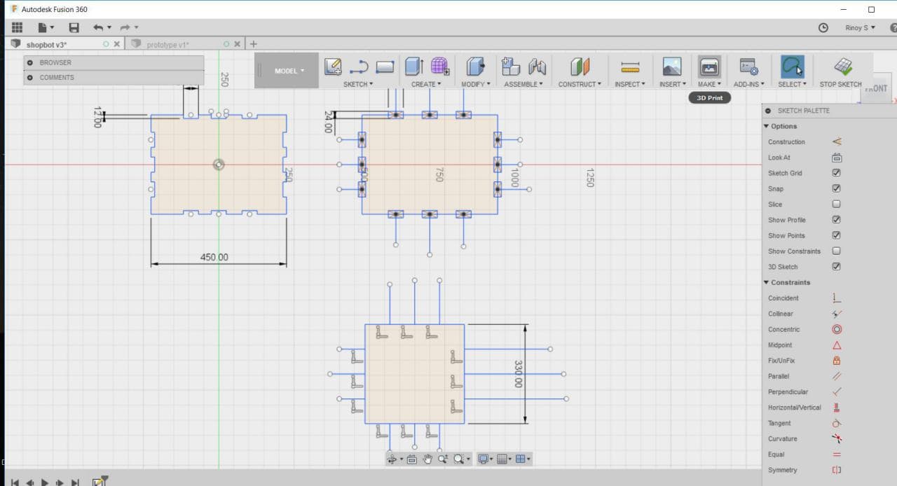
Also used to design during the time for Machine week
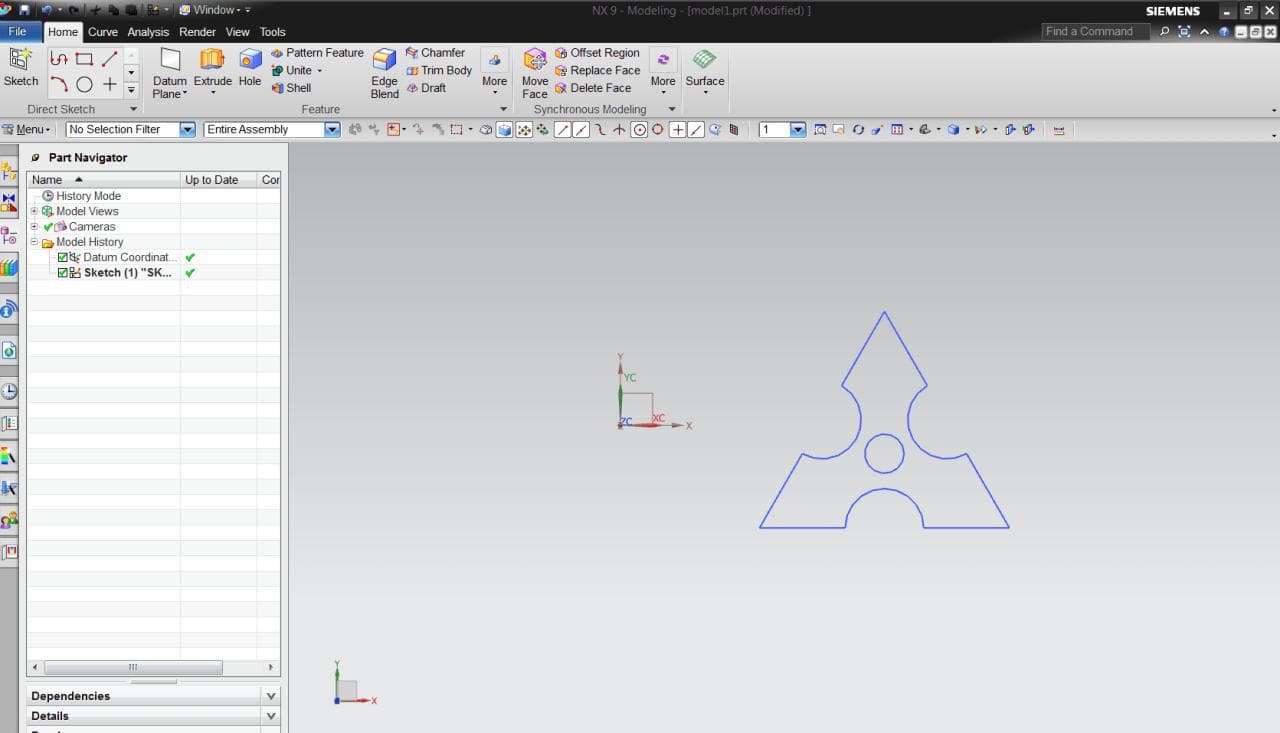
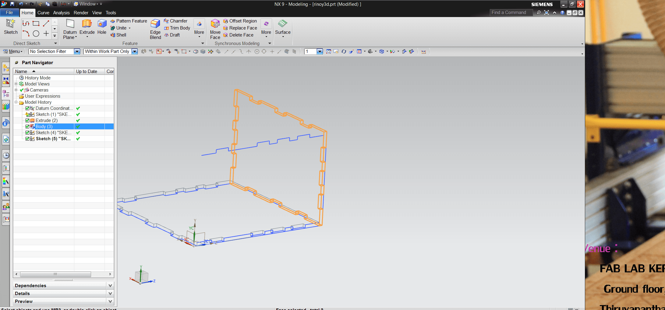
Siemens NX9
Siemens NX9 was learned at the time of Molding and Casting week
First I drew the model in 2D and extruded it
Using "Chamfer" I gave it the sharp edges
Inorder to make it smooth surface I Used "Blend"
Again drew a rectangle around the model and extruded it
Using "Subtract" I created a negative mold
I used NX9 for modelling my final possible project.In NX9 i modelled a 3D design, so it can give all the correct dimensions which can fit so that I can get create design in good manner.
First select a plane and draw a profile. We are able to give dimension at each end of the drawings
Can use fillet to set the edges
We can select the other plane and draw a new profile to join the 3D model
After drawing a rough sketch I was able to extrude with the dimension of the plwood width
After finishing my model, I exported the file as AUTOCAD DXF/DWG format to get the 2D design
after exporting I opened the file in Autocad inorder to arrange every single part, so it can be machined
NX9 gives a great idea how to draw in different planes
We are able to move or draw in 3D design itself
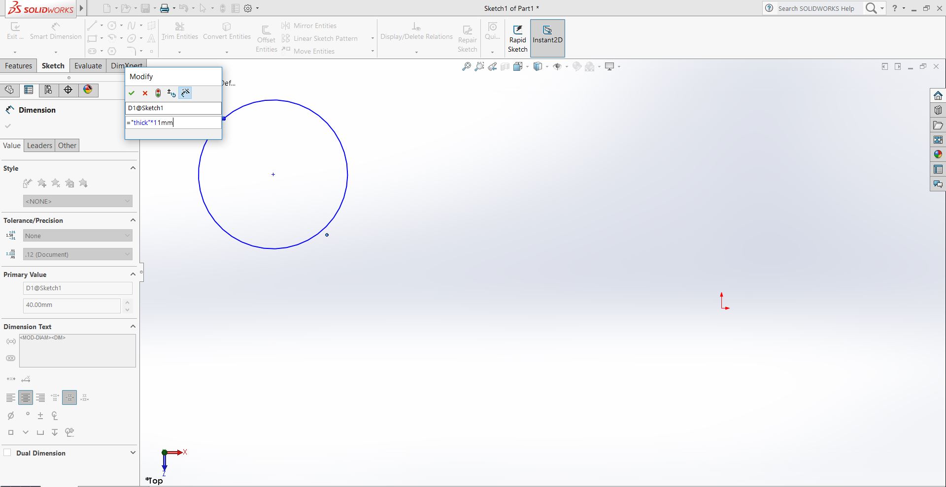
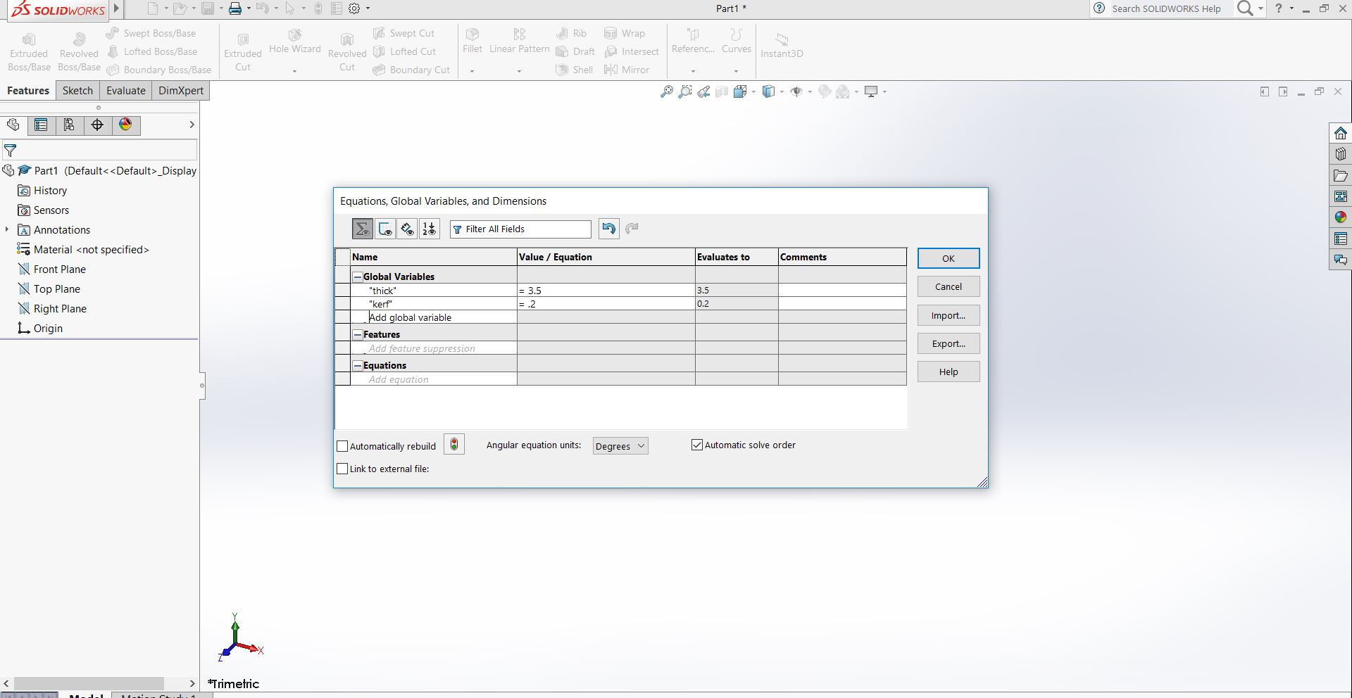
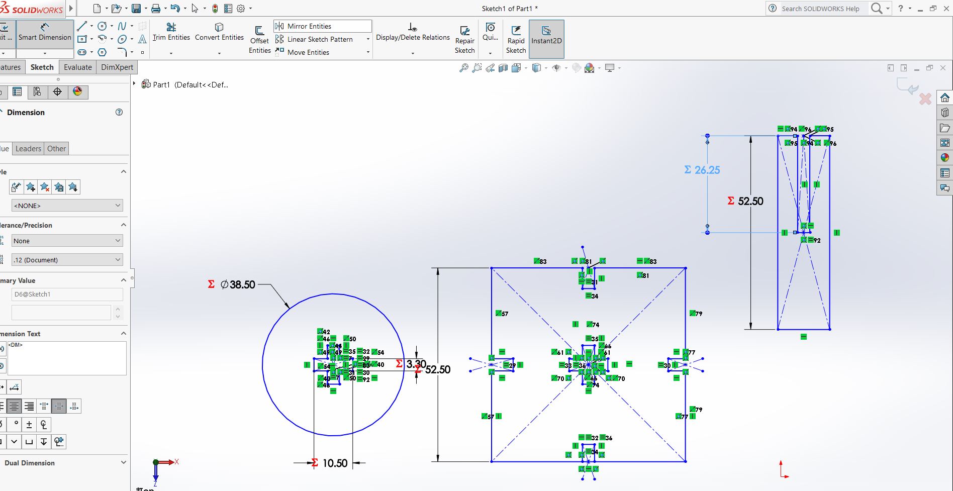
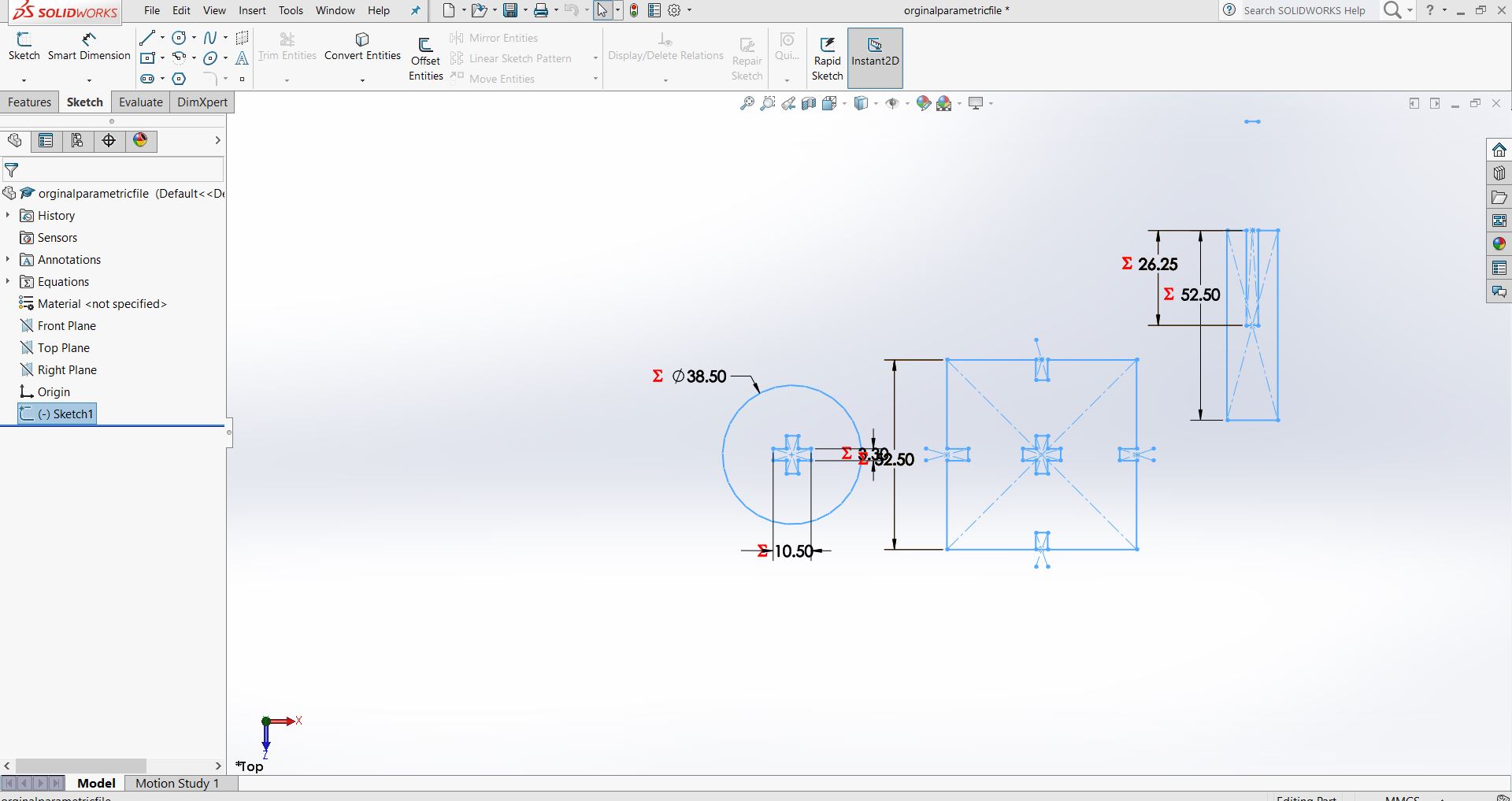
Solid Works
I used solid works for designing parametric
Set dimensions in "mm" and standars to "ANSI"
Drew Part
Selected Tools>Eguation>set Global Variable > Values
Drew Circle>Dimension>Modify>"Name">Value in "mm"
Trimmed