Home
Week Seven : Electronics Design
Assignment
Redraw the ECHO-HELLO WORLD Board and add atleast one button and an LED (with current limiting resistor)and check the design rules and make it.
ECHO-HELLO WORLD Board
For designing I came through a new software called "EAGLE"
Downloaded the latest version of Eagle and have downloaded the "fab.lbr" - a library function in Eagle, and added to the software.
Added new project >> Assignment
Assignments related to electronics begins with challenge, our instructors is quite helpfull in these challenging situations.
Wonderfull session on basic electronics and uses of components by instructors made this assignment bit easier.
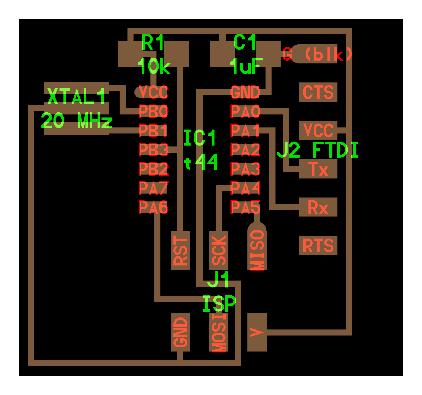
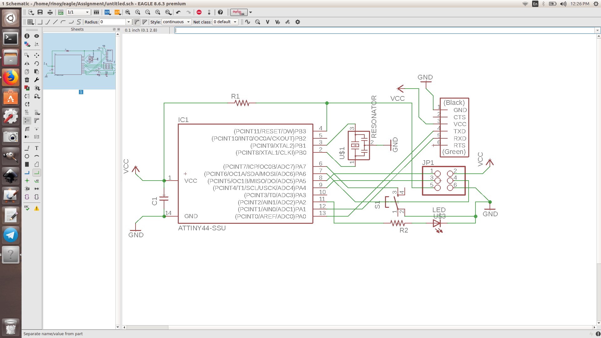
First Step : The schematic representation of my Echo-Hello board is as follows
I have added the components using a command "ADD", and connected the components using "net"
PCB - Printed Circuit Board, mechanical support and electrically connects electronic components using conductive tracks, pads from the sheet of copper layer.PCB is a simplest electronic product.
Here Im using a single sided PCB for my assignment.
Here we use ATTINY44-SSU Microcontroller to flash the Echo program on my PCB
Resonator is connected to Microcontroller, which acts as an external clock(connected to PB0 and PB1 of Microcontroller).The value of Resonator used is 20Mhz.
Capacitor(connected to PB3 of Microcontroller) is connected to Microcontroller, which is used to filter the ripple voltage.Value of capacitor is 1uF.
FTDI(connected to PA0 and PA1 of Microcontroller) chip is connected to Microcontroller, inorder to send and receive data to a programmer.
ISP pinout(connected to PA4 and PA5 of Microcontroller) is connected to Microcontroller, so that PCB can generate necessary programming voltage from system's normal voltage supply and to communicate with the programmer.
Resistor(connected to PB3 of Microcontroller)
Added extra Resistor(connected to PA2 of Microcontroller), LED(connected to PA2 of Microcontroller) and a switch(connected to PA6 of Microcontroller), which will be programmed on EMBBEDED PROGRAM WEEK
Second Step : Switch to Board
File >> Switch to Board
Here I had to arrange every components manually and orderly.Border dimension are set here.

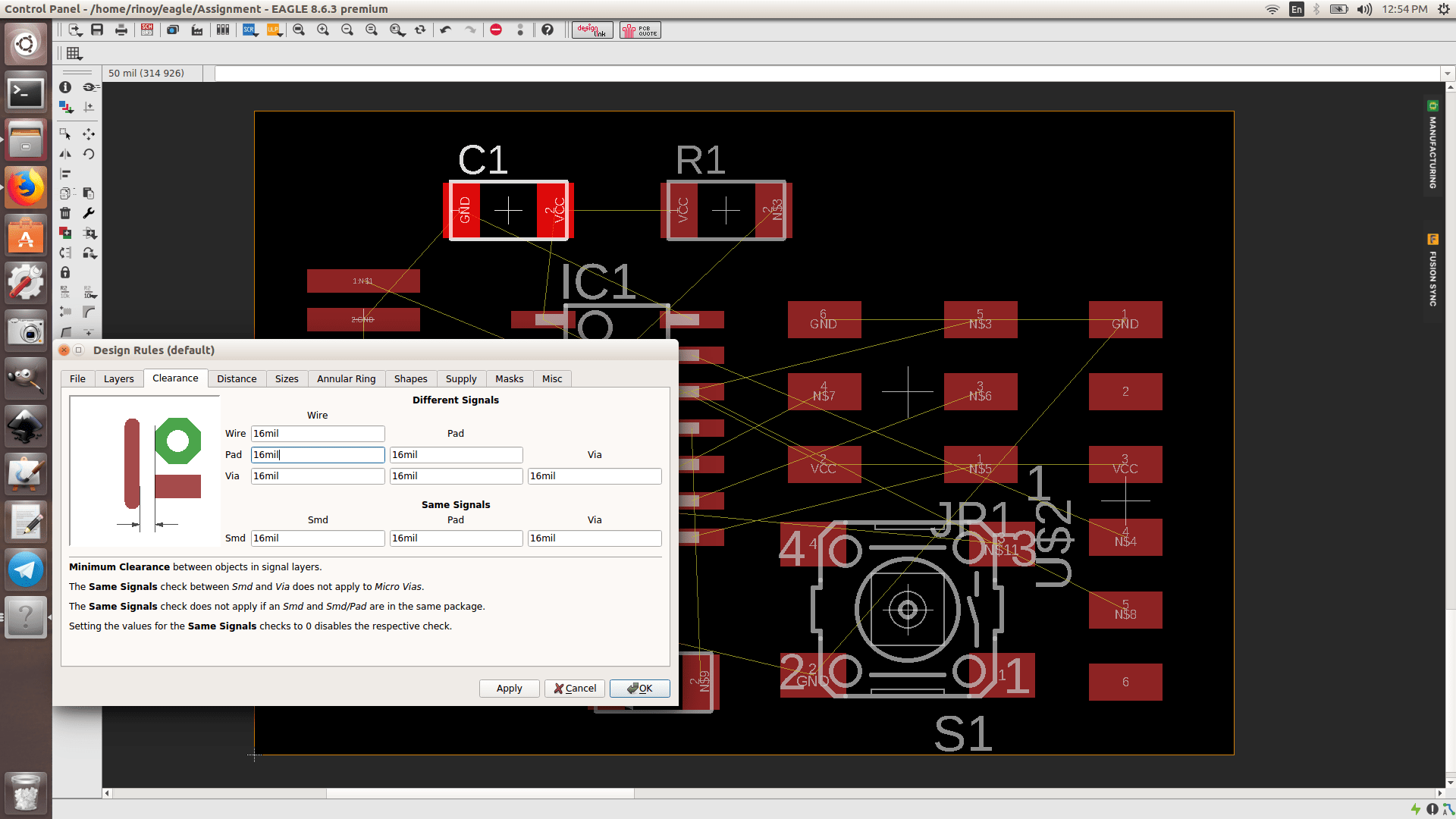
Third Step : Set Design Rules
Had set Clearance values - 16mil for Wire, Pad, Via and SMD
Had set Clearance values - 18mil for Size
Edit >> Design Rules
Fourth Step : Set AutoRouter
Had autorouted many times to make 100% optimized.
Tools >> AutoRouter
Set
Preferred Directions >> Top >> (-) and Bottom >> (NA)
Efforts >> High
Continue
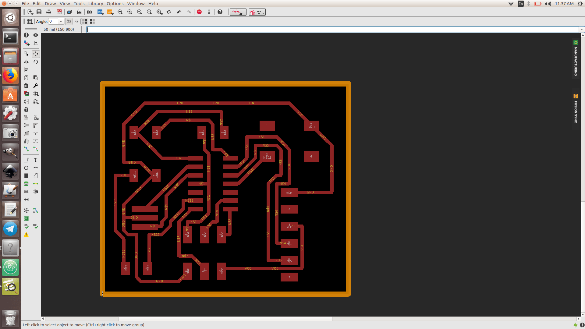
MY BOARD DESIGN
Designed and border width is set.
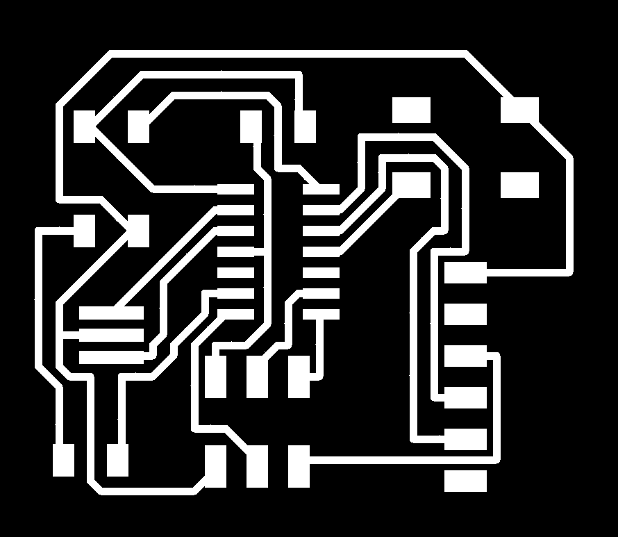
Fifth Step : Set trace to Mill
Had exported from eagle with monochrome and with 600 pixel.
Layer Settings >> Top and Pads
File >> Export >> Image >>Select Monochrome >> Resolution - 600 pixel
OK
Sixth Step : Set trace to Cut
I had a extra surface at the bottom, I covered that by using GIMP, Tools >> Paint tools >> Bucket fill
Layer Settings >> Dimension
File >> Export >> Image >>Select Monochrome >> Resolution - 600 pixel
OK

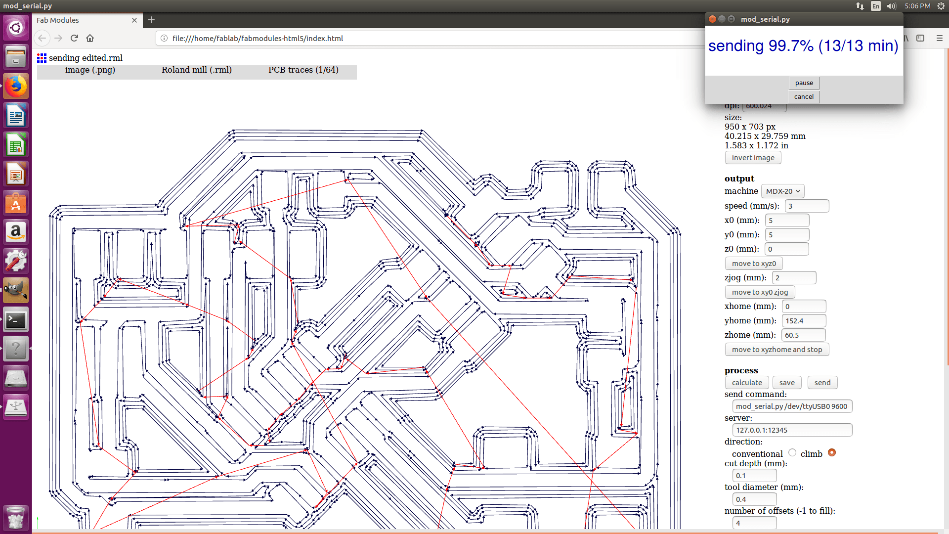
Seventh Step : Milling
Used fabmodules to create the file for milling and Cutting purposes.
1. Load the PNG file(mentioned in 5th step)
2. Select Roland Mill
3. Select tool >> PCB traces 1/64
4. Set bed axis
5. Set the speed
6. Calculate and Send
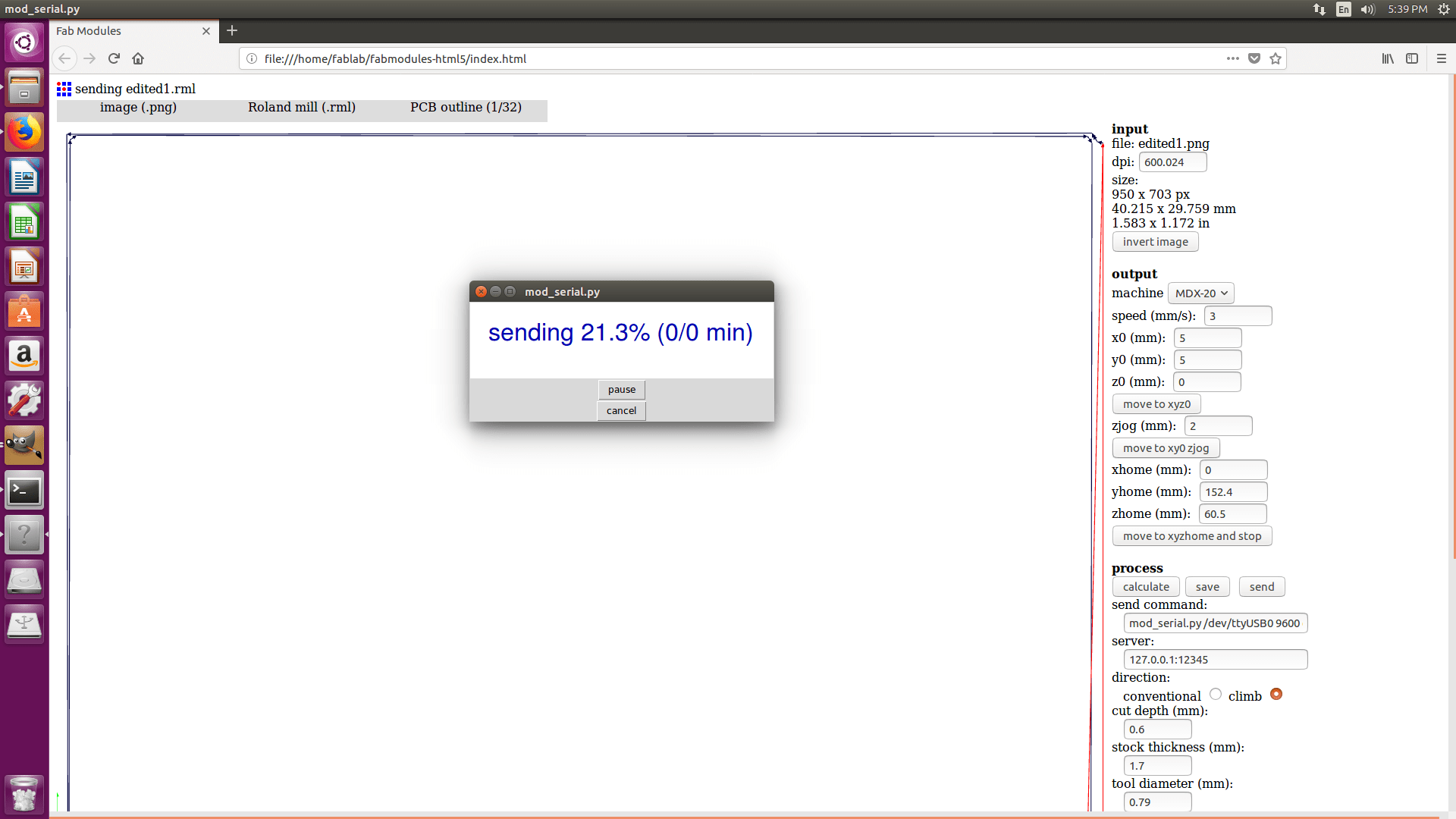
Eighth Step : Cutting
1. Load the PNG file(mentioned in 6th step)
2. Select Roland Mill
3. Select tool >> PCB traces 1/32
4. Set bed axis
5. Set the speed
6. Calculate and Send
Ninth Step : Soldering
Soldering is the process in which two or more items joined together by melting solder wire into joint.
1. Soldering wire used is Lead
Lead has low melting point, so it is easy to solder components with PCB
2. Soldering Flux
Flux is used to prevent Oxidation of base of PCB and components
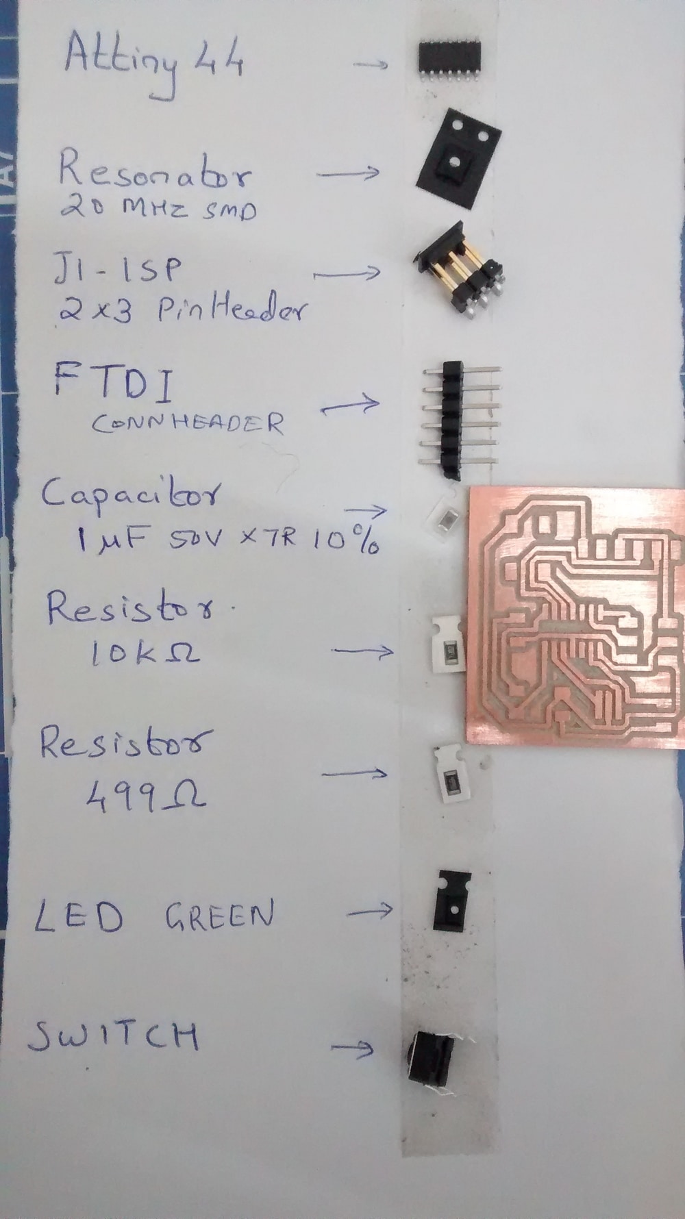
Added all components needed for Echo-Hello World Board, namely -
1. 1x ATTINY44-SSU - SOIC14
2. 1x FTDI-SMD-HEADER
3. 1x RESONATOR
4. 1x PINHD-2x3-SMD
5. 1x CAP-UNPOLARIZZEDFAB - C1206FAB
6. 1x 6MM-SWITCH - OMRON SWITCH
7. 2x RES-US1206FAB
8. 1x LED FAB1206
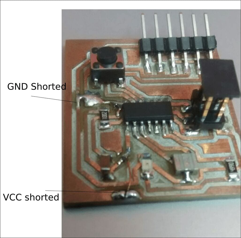
My PCB
Here I made a mistake of not giving VCC and GND to Microcontroller.I have soldered GND and put a jumper using copper coated wire to connect VCCs
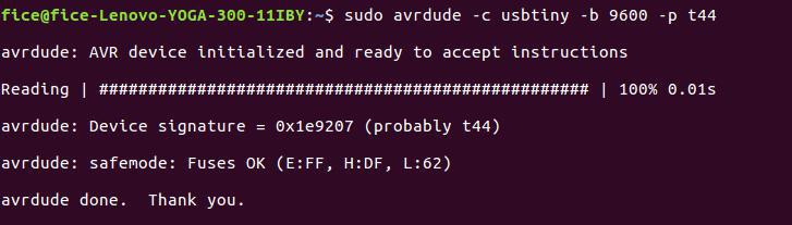
Communication is checked using
sudo avrdude -c usbtiny -b 9600 -p t44
Tenth Step : Programming - Make fuse
Downloaded .make and .c file from schedule in Fabacademy
Renamed .makefile to Makefile
Connect USBtiny to ECHO-HELLO BOARD
Open terminal and enter
make
make program-usbtiny-fuses
make program-usbtiny
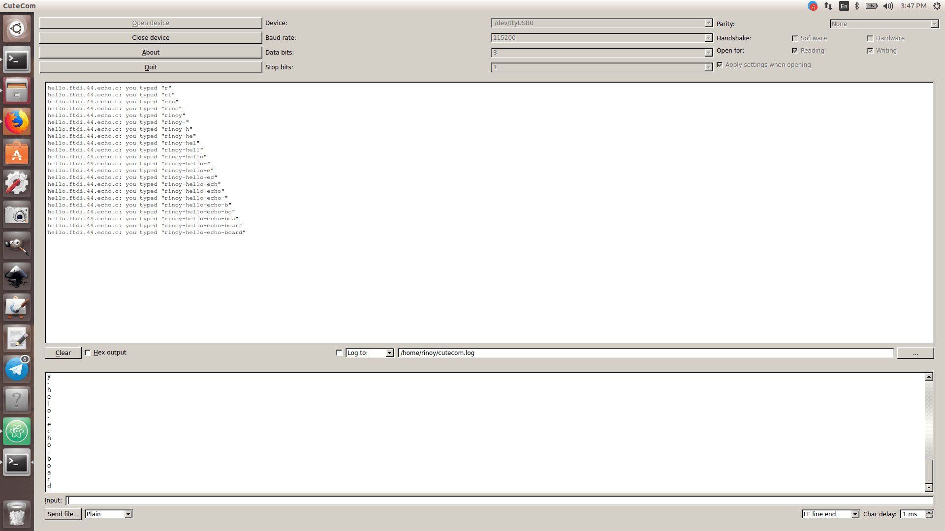
Step Eleven : Install Cutecom and Repeat ECHO-HELLO.
sudo apt-get install cutecom
Connect ECHO-HELLO BOARD to USB-Serial Converter
Add device
Check the working of ECHO-HELLO BOARD
Group Assignment
Characterize the specifications of your PCB Production Process
Our Instructor Vinod gave us great idea on Dual Channel voltage regulator, Digital Oscilloscope and Arbitary Function Generator.
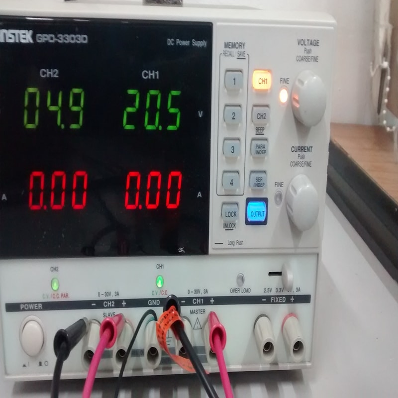
Dual Power Supply
This device can adjust or vary from 0-30V
There is two channels in this device - where we can draw upto 3Amp current
There are individual GROUND and POSITIVE for each channel and common NEGATIVE
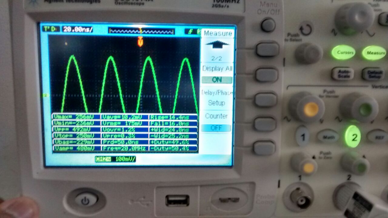
Digital Oscilloscope
This device is used detect signals like Amplitude, Time and Frequency
Contains 2 channels so, Can check upto 2 devices using this machine
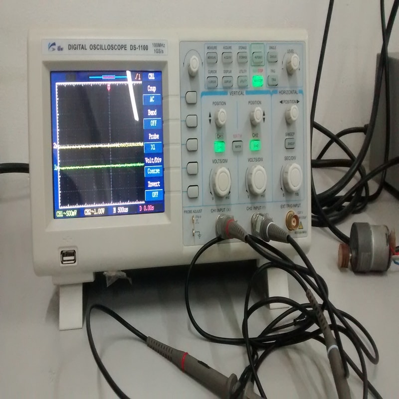
We checked our board and measured the value of Resonator.
It shows the actual value of 20mhz in display
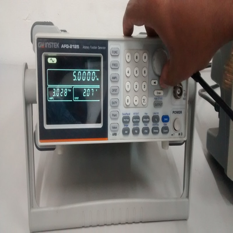
Arbitary Function Generator
This device is used to generate waveforms like Square Wave, Sine Wave, Pulse, Triangular Wave, Noise
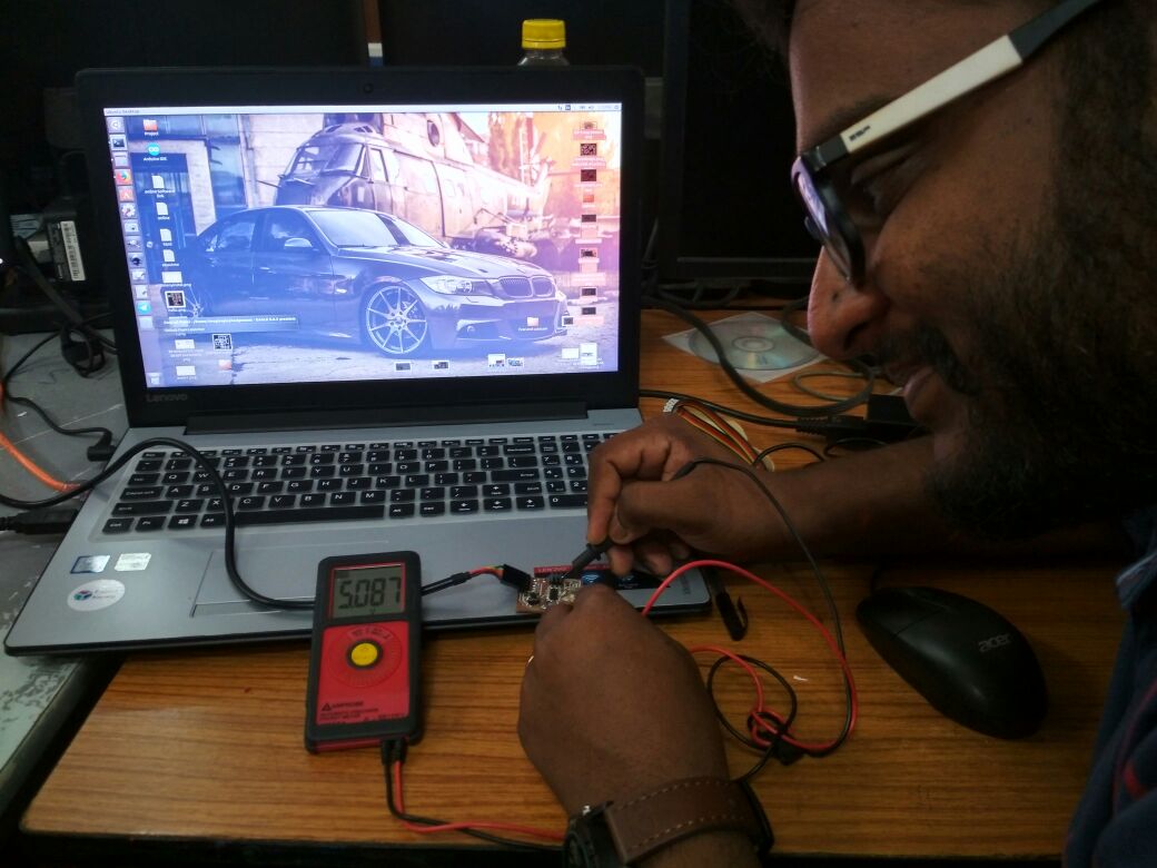
Multimeter
Multimeter is used to measure Voltage, Current and resistance
Multimeter is also used to trouble shoot electrical problems
Multimeter is a combination of a multirange DC voltmeter, multirange AC voltmeter, multirange ammeter and multirange ohmmeter
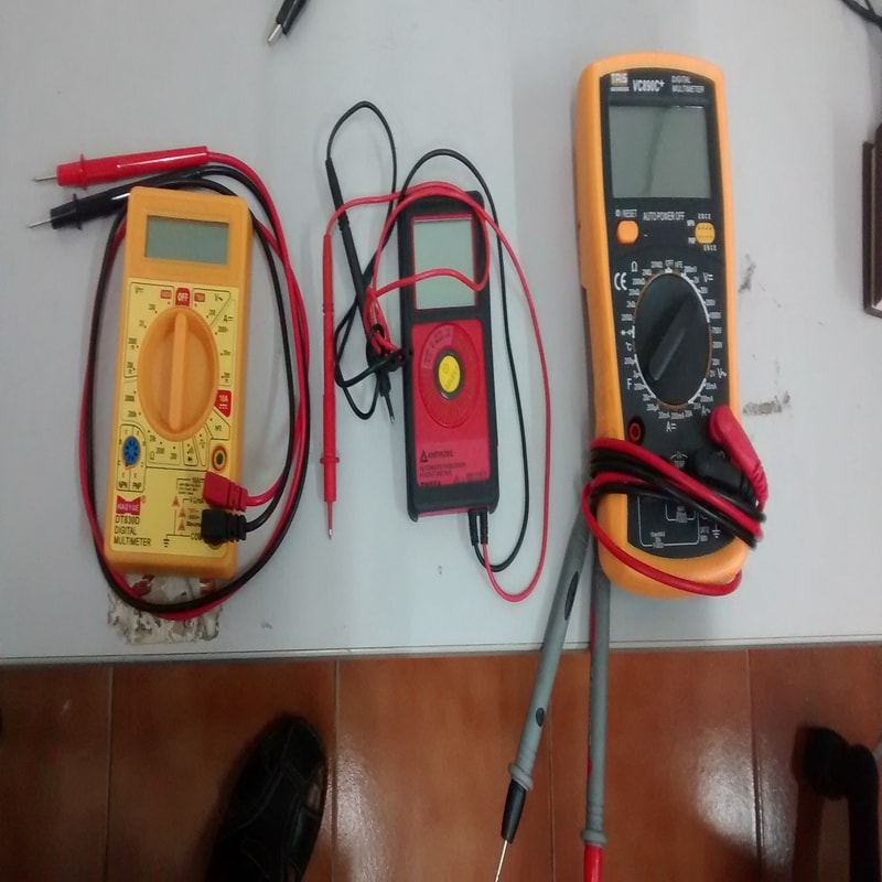
Checking the Power Source Voltage of my PCB and output voltage is 5.087