This week also we have an electronics assignment and have to deal with Output devices.So the basic methodology is same as last week,we have to add
an output device instead of a sensor form the last week and program it to do something.From Neils lecture we have got an idea of different output devices and his boards and examples
was easy to understand.Apart from Input devices where I modified Niels Board on sonar sensor,this week I wanted to design my own board for completing this weeks assingment.
OUTPUT DEVICES-LED AND ITS WORKING
In google, output device is any peripheral that receives some data from a computer or a device, usually for display, projection,or physical reproduction.
There are many output devices available like speakers,leds,lcd,stepper motor etc.Out of these I have chosen LED for my assignment.The first visible LED was invented by Nick Holonyak in 1962
while he was working for the General Electric Company.It was red colour led using gallium arsenide phosphide as a substrate.
LED
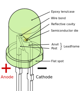
According to wikipedia,LED is a two-lead semiconductor light source.
It is a p–n junction diode that emits light when activated.When a suitable current is applied to the leads,electrons are able to recombine with electron holes within the device, releasing energy in the form of photons.
This effect is called electroluminescence.
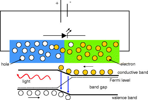
Working of an LED
you can read more about LED and its working here
Referring to Neils lecture,I had found two of his boards,
one with an RGB led and other an led array arrangement.After some reading I googled down other application of lED's as an output device and came across POV (persistance of vision) displays.
PERSISTANCE OF VISION
Persistence of vision [wiki] refers to the optical illusion that occurs when visual perception of an object does not cease for some time after
the rays of light proceeding from it have ceased to enter the eye i.e., image seen by our eye persists for about 0.04s during which any other images that we see are merged together with this image.
This technique is used with the help of LEDs for creating displays.Lot of animations can be done using this
technique.
In youtube I have found out lot of interesting projects in LED POV displays.I am sticking on to a normal one that to display a word using this board.
DESIGNING THE PCB
Autodesk Eagle is used for designing the PCB.I have chosen ATtiny44 microprocessor for this weeks assignment.The Pin configuration is as follows:
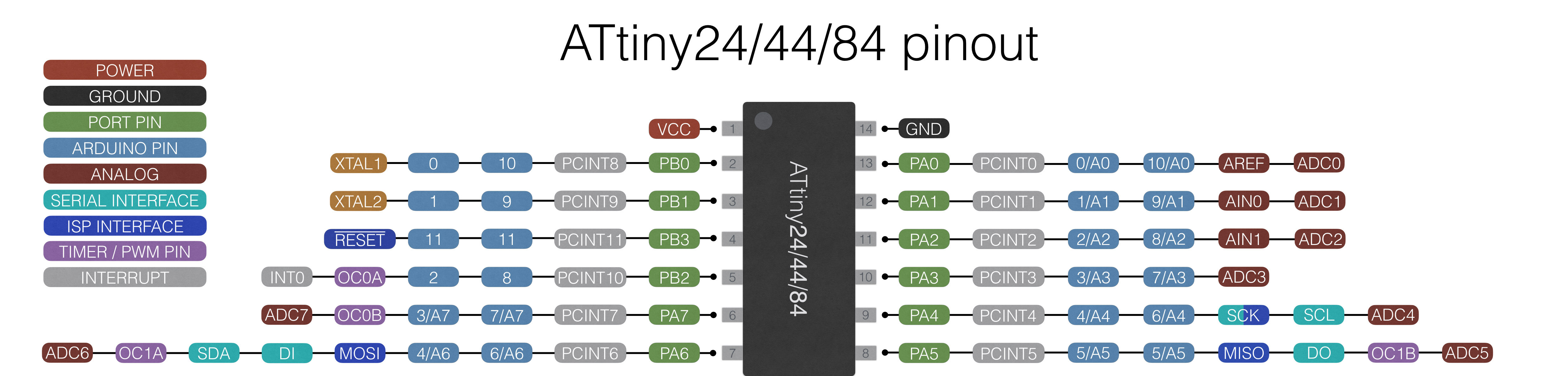
ATtiny 45 pin configuration
Designing the PCB this time has some points to note down.I have to arrange 6 leds which i have chosen for the display in a series and their
current limitting resistors in parallel to those leds.So while designing the circuit for that I had undergone two mistakes.
Firstly,I had misarrranged the pins for ISP connection and pull up resistor for reset pin was connected to ground insted of Vcc
.
These mistakes was debugged only at the time of programming.
The PCB design methodology is same as the previous assignments,listed as :
1).Open eagle and create a project,in,mark that create a schematic.
2).Add components in schematic using ADD command.
3).Connect all the components using net tool or use label and name option to connect them,which I prefer to use.
4).Perform the ERC check and swi
tch to board.
5).Modify the design rules for clearances as 16 mil and size of traces and 18 mil and arrange the components.
6).Route using autoroute or manually route.
7).Perform the DRC check and export as png for milling.
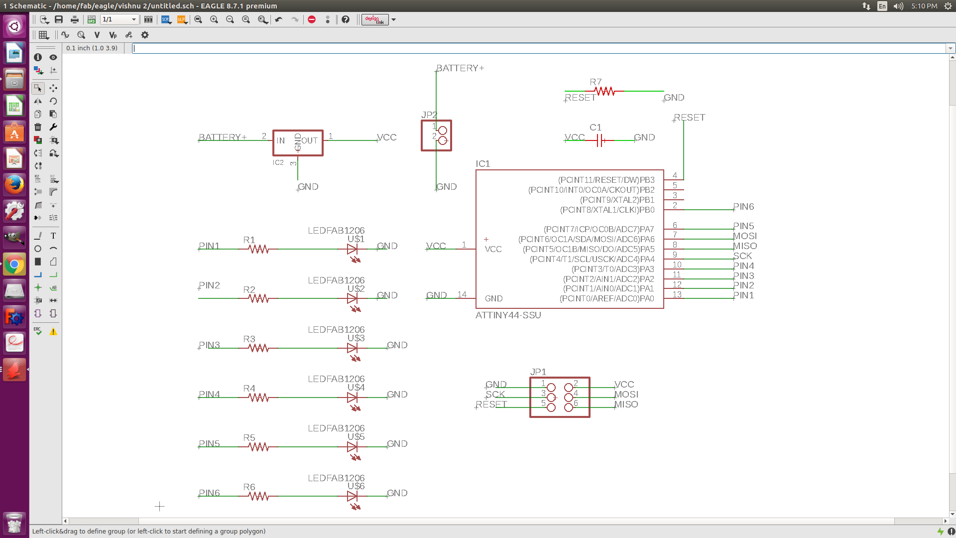
Schemaic sketch of the board
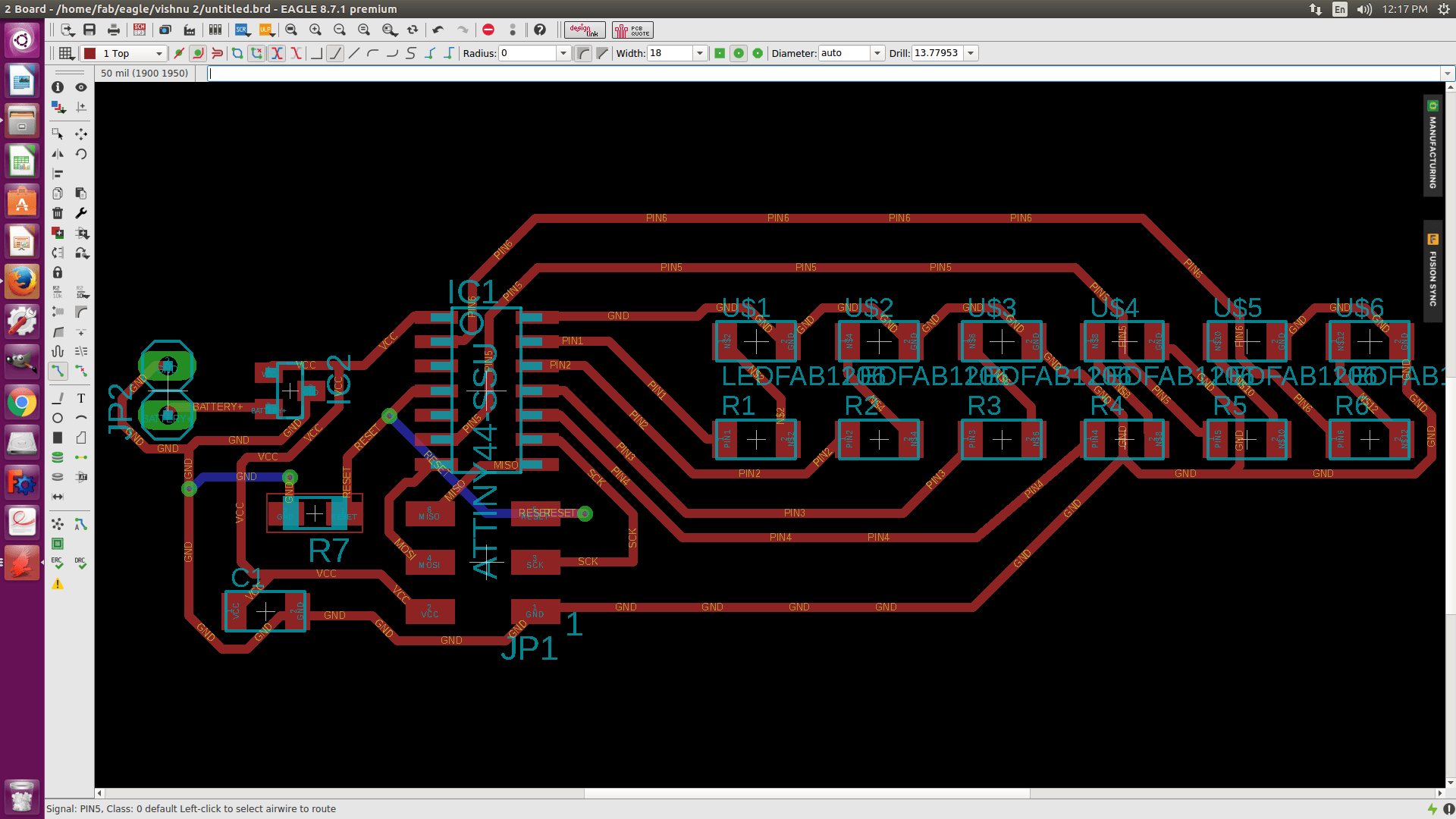
Board after routing
MILLING THE BOARD
For milling the board I am using Roland Modella MDX-20.
This time for milling I have been asked to try with a 0.4 mm V-bit for milling.It gave good result but we have to be careful with the gravity fitting of the bit on the Z-axis.
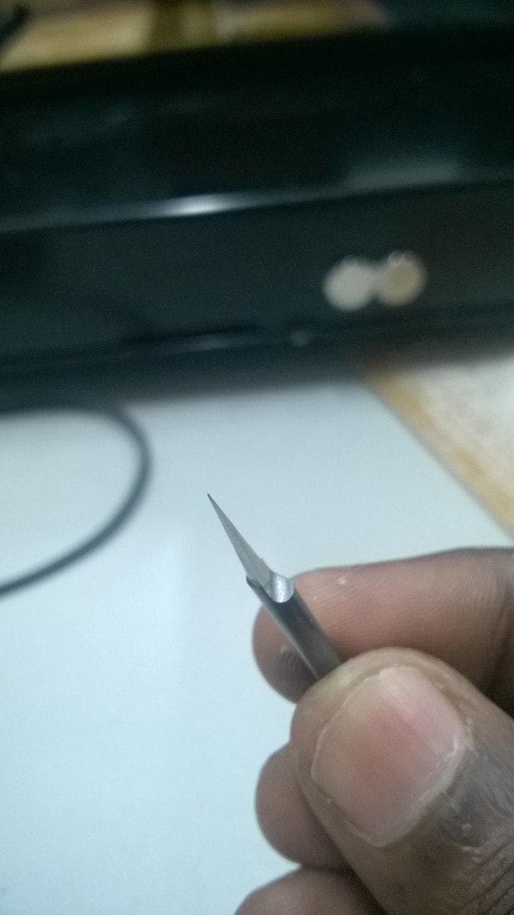
0.4 mm V-bit
For cutting 1/32 nd inch bit is used
Fabmodules is used as the print manager
The setting up of modella MDX20 and using is explained in my Electronics production week
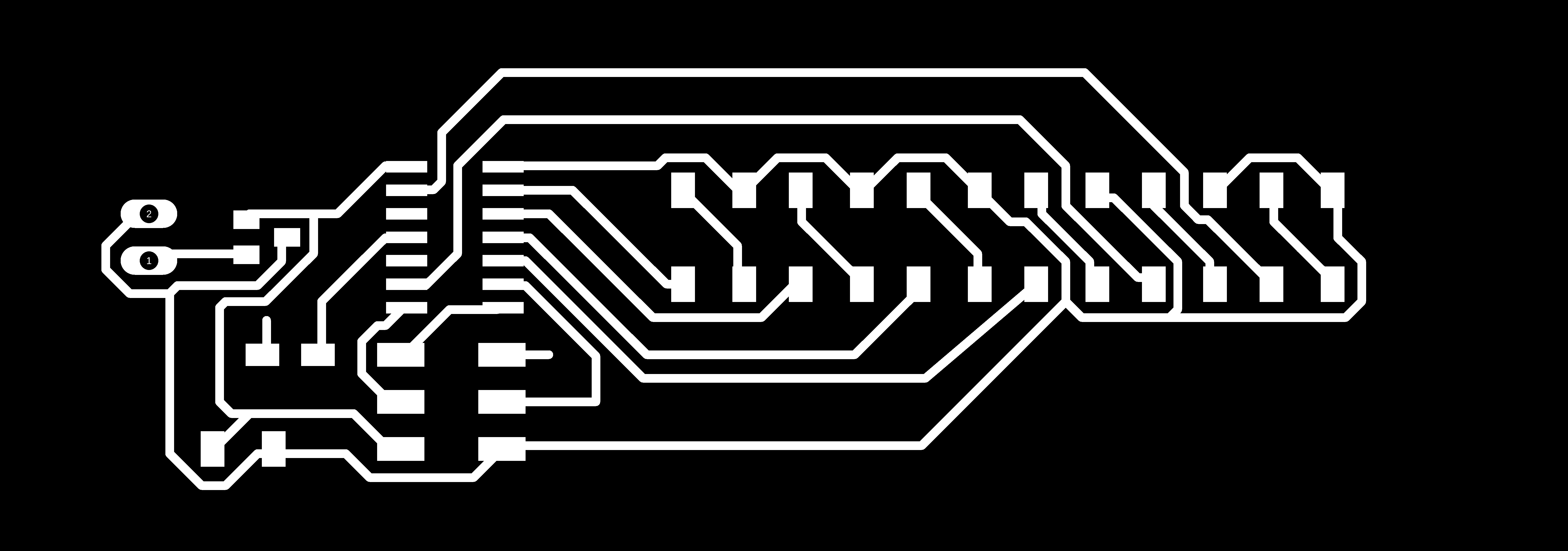
Traces for milling
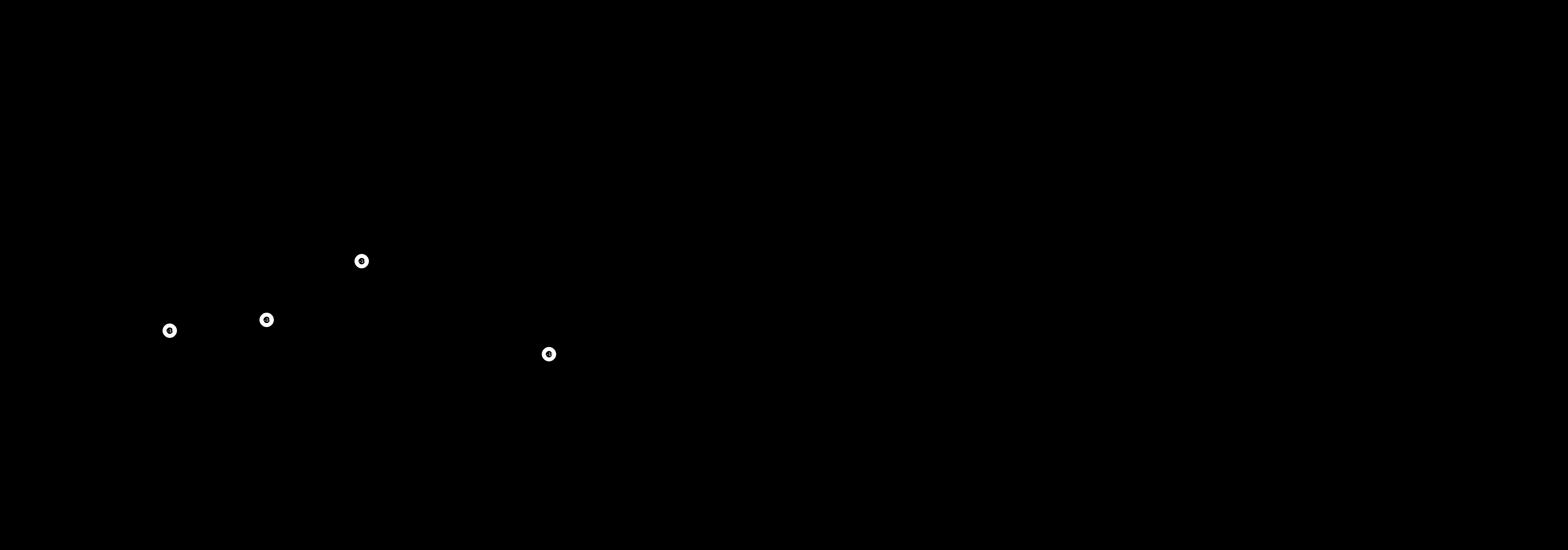
outline for drilling

outline for cutting
For cutting 1/32 nd inch bit is used
Fabmodules is used as the print manager
Components Required
ATtiny44 microcontroller
smd led 6 numbers and its corresponding resistors
AVR ISP SMD header for programming the board
voltsge regilator SOT-23
10 kilo-ohm resistor
499 ohm resistor x 2 for leds
10 microfarad capacitor
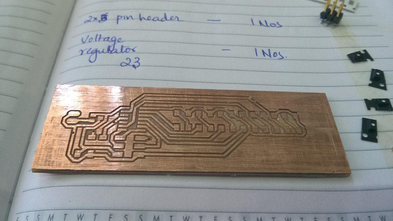
board after milling
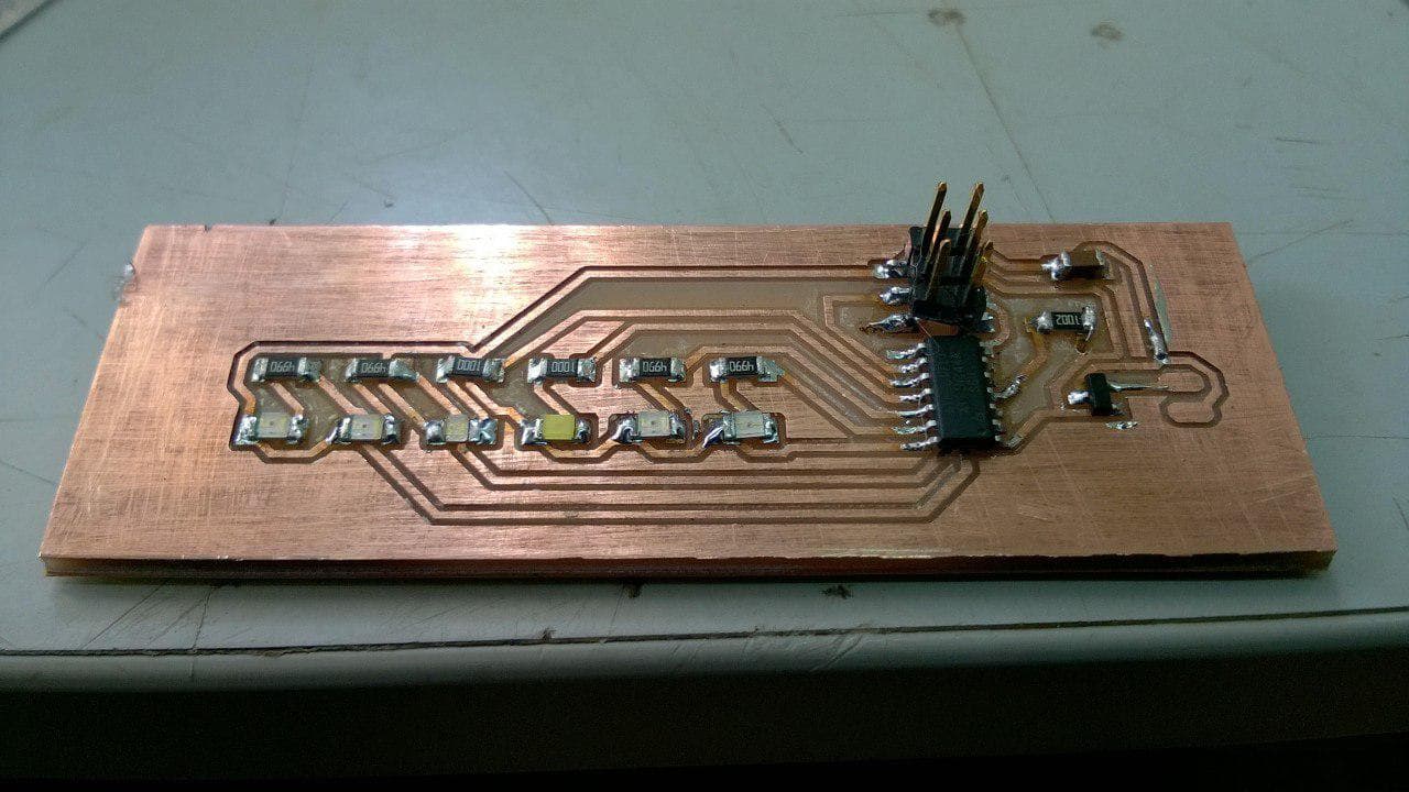
AFTER SOLDERING
PROGRAMMING THE BOARD
For programming the board I had used Arduino IDE.In Aurdino first
we have to select the programmer,board,processor and the clock before writing the program.For my board the details are as follows:
Board-ATtiny 22/44/84
processor-ATtiny 44
clock -8 MHz internal
I am very much new in coding and so I am using a code which I came across in internet modifying it to my needs to run the
program.During this stages only I came to know my early mistakes in designing the Board.
Problem 1.COMPILE ERROR
The code was a long one and it didnt compile showing error ,not enough memory available in the board.This made me to check the reason behind it.As most
of the coding uses char datatype,char takes I byte of memory for storage.This made me to modify the code for compiling.I was also instructed to write the
code in C language to resolve the memory issue.
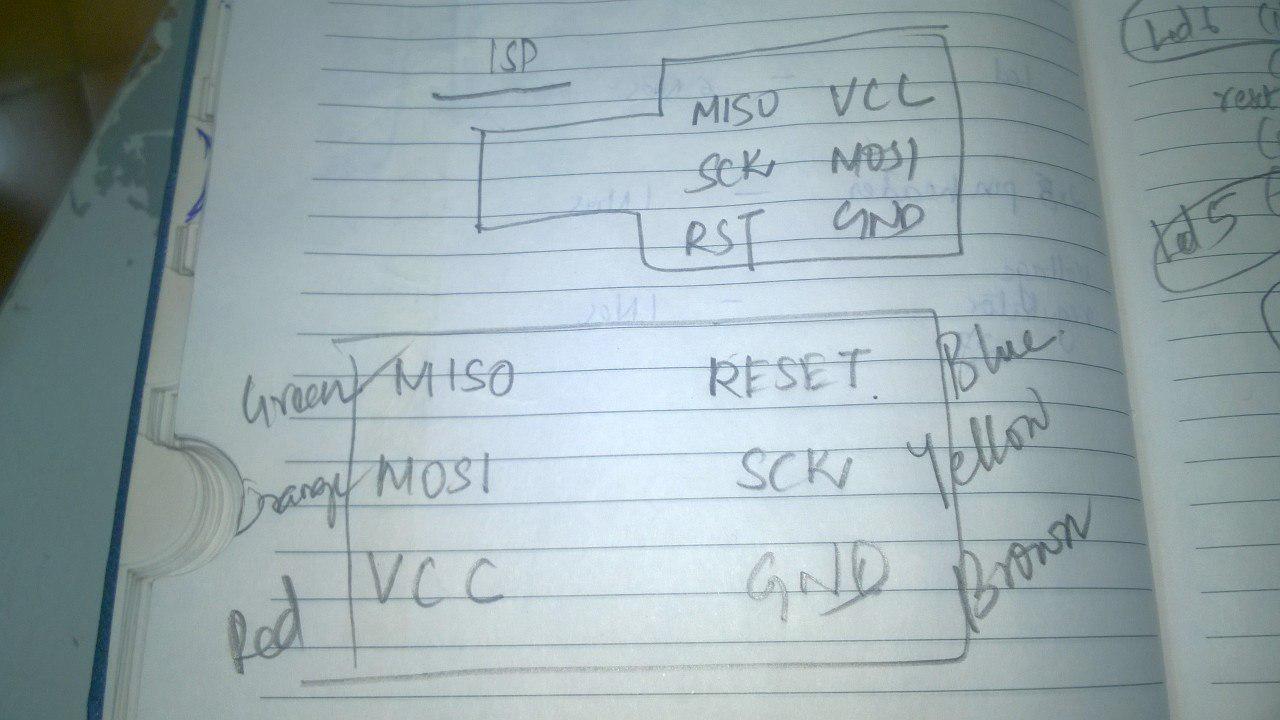
Problem 2.MISARRANGED THE ISP COMMUNICATION PIN
This problem occured because I needed to avoid jumbers for my led display.this was resolved by using female to female jumber cables for connecting USBtiny and my board.For
this i had to draw both the pin configurations in a paper and write down the colour of the jumber wire used.
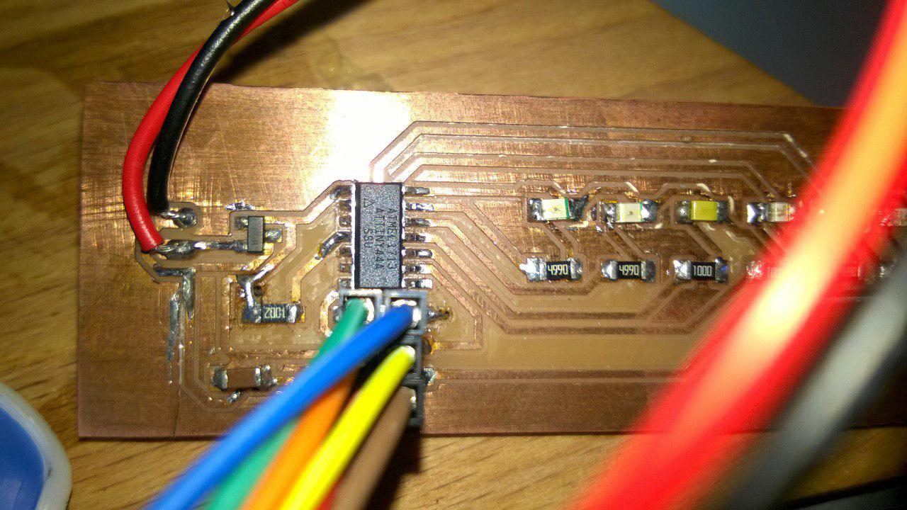
Problem 3.PULL UP RESISTOR CONNECTED WRONGLY
The pull up resistor for pulling the reset was connected to the GND insted of Vcc that too using a jumber which otherwise could be directly connected.I desoldered the jumber wire
and made a solder bridge to resolve the problem.
WORKING OF BOARD
For the board I came across an Arduino code in youtube,modified it to my needs and used for programming.The code required lot of memory
which was not available in Attiny 44 ,so I had to hide some character codes and use only which is necessary for my program to run.Also I included a character for
providing space after the word.
After flashing the code, I connected my board to a 9V battery using a battery cap.It was seated on a scrap beachwood holed
using a drill in the centre and a DC motor is fixed to it and it was powered using a Voltage regulator.
I wanted to display "FABLAB" and the first output is shown below:
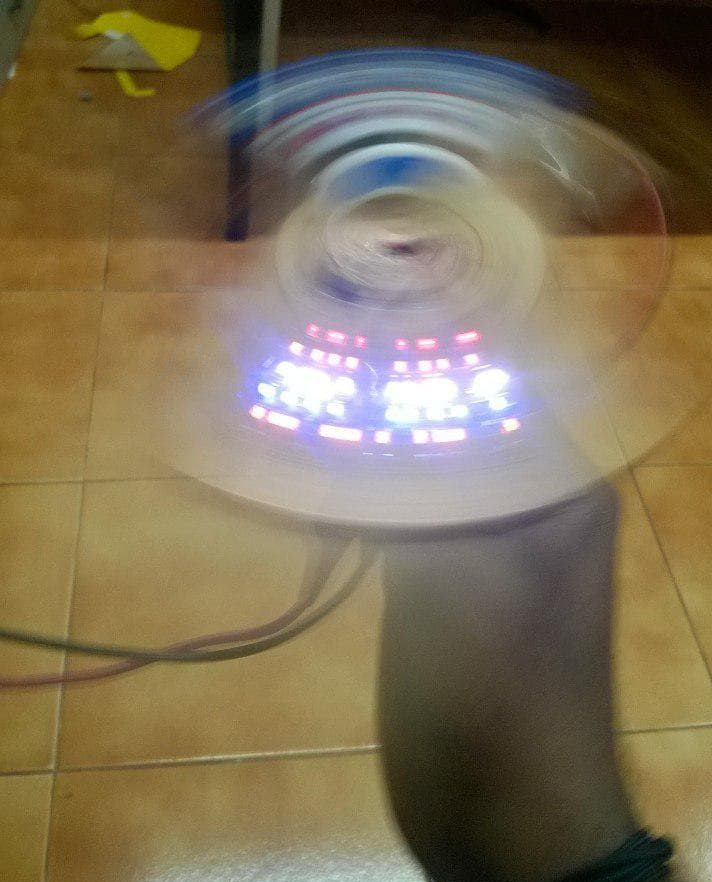
The display was not coming correctly,lot of troubleshooting was done, the centre of gravity was checked and the whole item was reassembled,the delay time was varied and checked. The next day I wanted to try something with a larger RPM and at the same time my instructor Vinodkumar asked me to try with the handdrill.It has a larger RPM and the whole assembly was set to it and our checking continued.
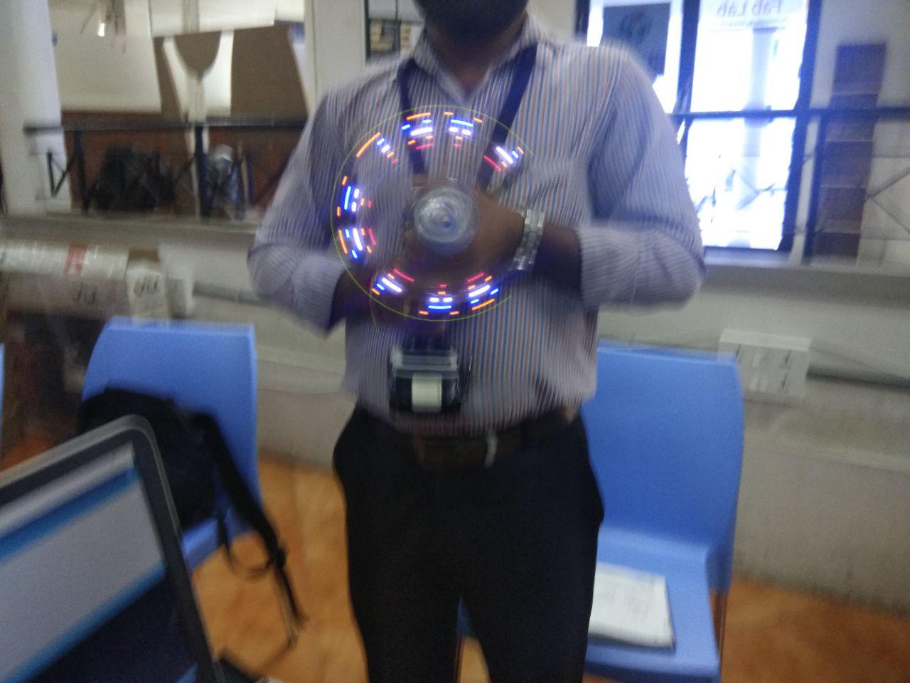
The display which came out was not stable.After a whole day of troubleshooting this was the result we had acheived eventhough I was not fully satisfied.Here is a video of my output board displaying "Hello".