The machine group assignment week has come up and our job is to design and operate a machine.We have two weeks to complete our task and the first thing
we did is to sit around a table and write down our ideas.The first day of the week was spend for this and nothing else,to select an idea as a group,study the scope,machine actuation,parts needed,
decide wheather we could complete building it within the time-period and concrete our mind in building it,so that the most important part of our assignment is completed.
We decided to write down atleast three machines by each member and select from them.When we were discussing we found out these ideas good,namely:-
1. Tactograph - Tactile image printer by extruding fevicol
2. Object tracking camera mount with roll, tilt and pan
3. Braille Printer/Embosser
4. Object Shooter
5. Wall printer
6. Automated drink mixer
7. Dosa Maker
Out of these,my suggestion was wall printer(A portable printer which could be fixed and directly print on wall).We discussed the possibilities of each machine,building ease ,googled each and found some interesting examples.
Later towards the end we choose Braille printer suggested by Abhilash as our machine project.
BRAILLE PRINTER
LINK TO OUR GROUP PAGE:- VISIT
A Braille printer is a device that renders Braille alphabets into tactile Braille cells by either embossing or making projections.So in our version of
the Braille printer we are using Stepper motor to control the movement of the head and paper and solenoid as the endeffector.So the basics are clear and we moved on to our working.
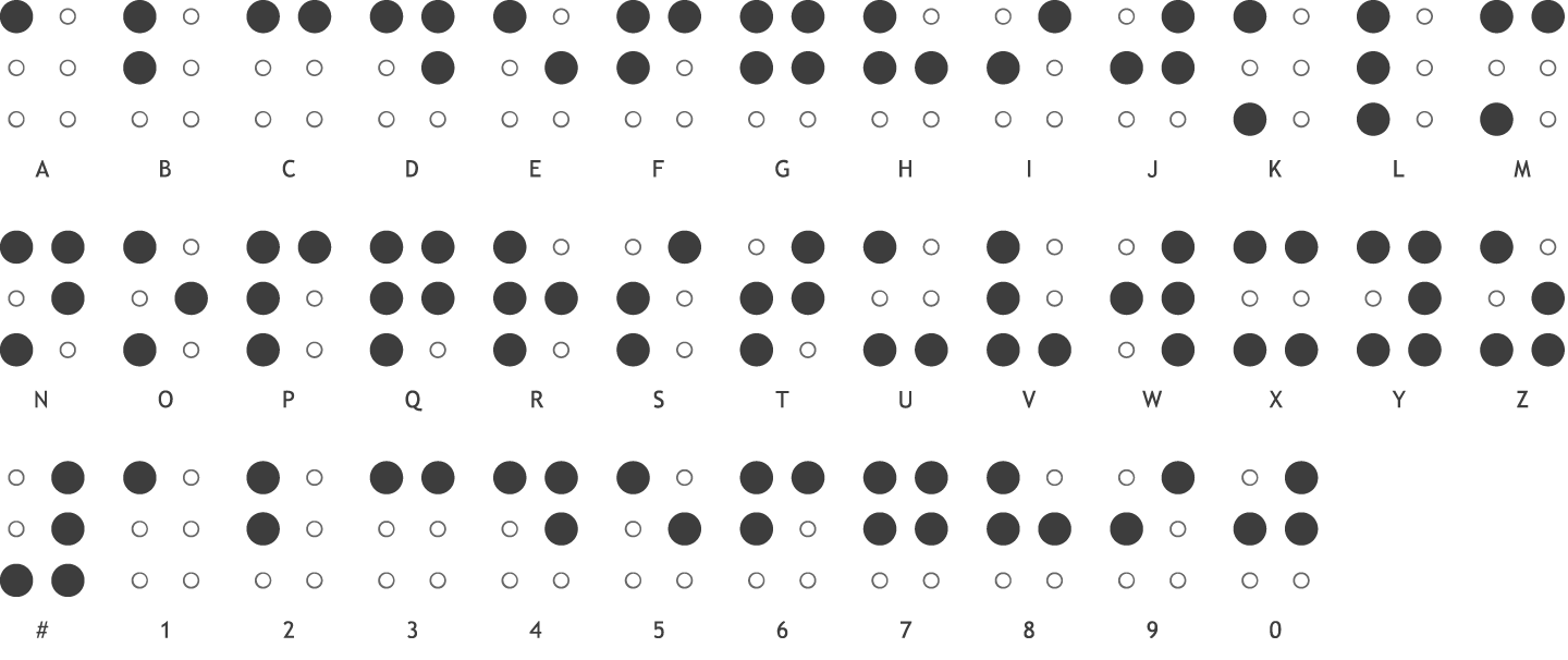
braille alphabets
I had an old dot matrix printer with me (which is not in a working condition)and we had tweaked it to study the arrangements.Each of us were very much excited to disassemble the printer and study its parts.We could use the paper slider and some small bearings from that dead machine.
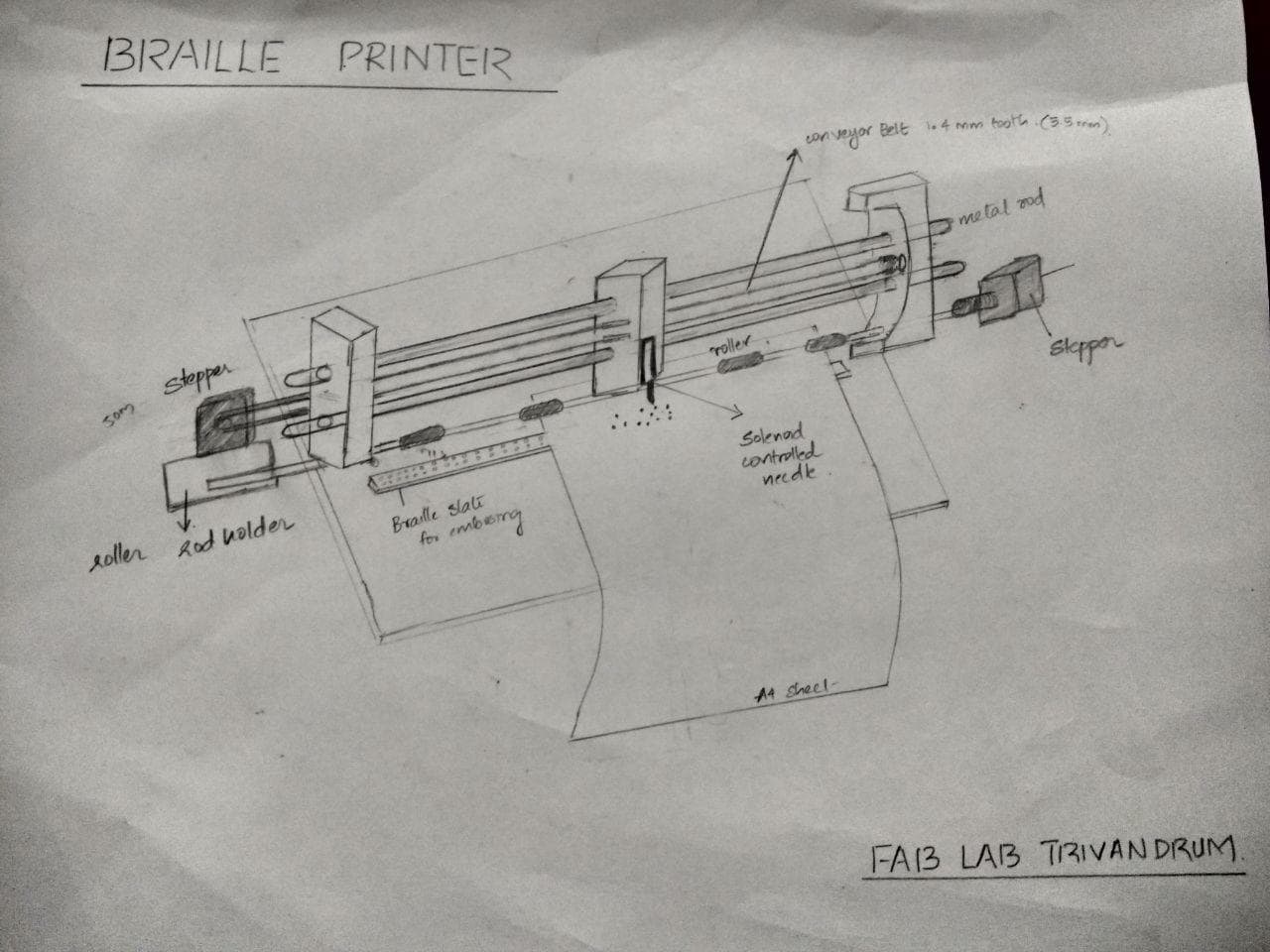
A paper drawing of the braille printer
Now we began to divide each tasks.We choosed a peculiar way in designing the components i.e.,while designing a part one will assist that guy in measurments and building.This would reduce the
errors and if soo happened we could easily rectify it.
My tasks include purchasing of items,designing of base,designing of solenoid attatchment with needle,assembly of parts(common to all) and connection wirings.
Apart from this I could also assist Aby and amith with the 3d design of the printer with the whole assembly.
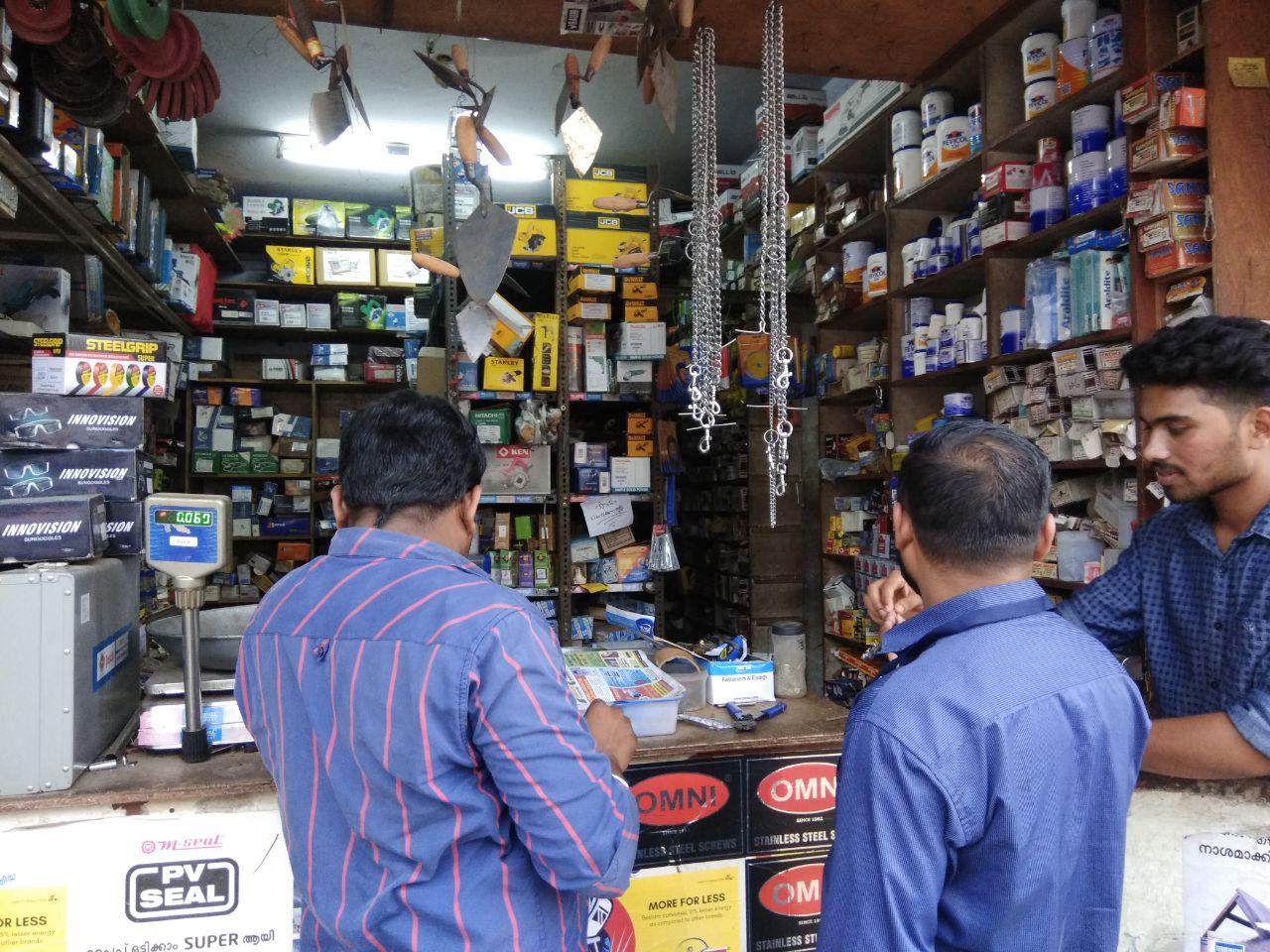
PURCHASING OF ITEMS
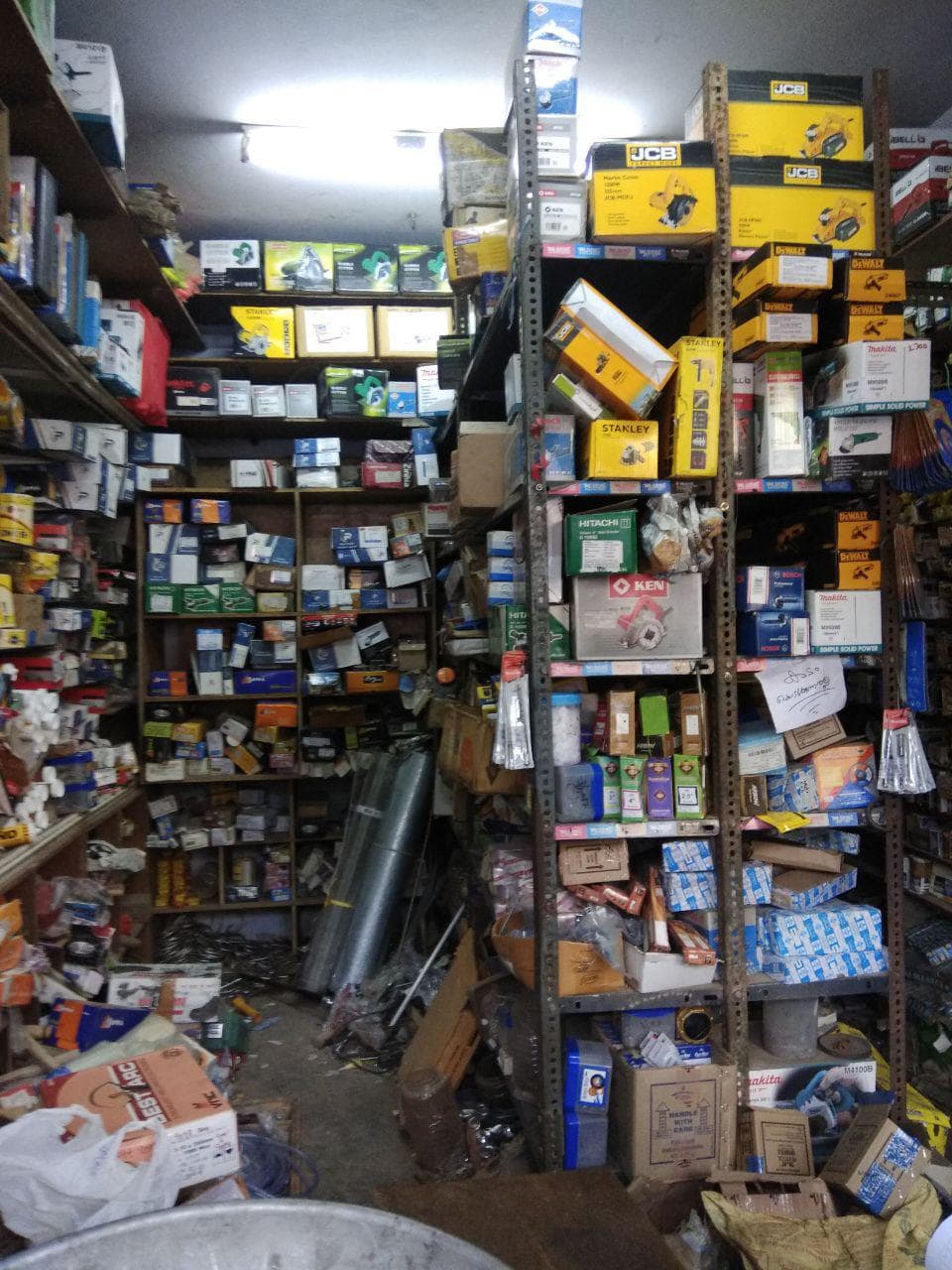
Shop we visited to buy the items
Amith and akhil was doing the inventory and the items we need are:
Stepper Motor - 2 (one for printer head movement and one for rolling the paper)-available in our lab
8mm smooth Rod for moving the head
GT2 betl(1.4mm tooth)
Driven pully and driver pully
solenoid
coupler for connecting roller with stepper motor
bearings and small screws
Eventhough me and Aby was assigned to purchase,rinoy abhilash and our instructor Vinod also accompanied us.We could get all the items except solenoid which was ordered online.
DESIGNING OF BASE WITH STEPPER
After purchasing the items they had made a side wall for the rod in laser and a head assembly unit was 3D printed by akhila and had asked me to design the base and a locking system for the stepper motor.The stepper motor is having dimension 42mmx42mmx42mm .I used Inkscape to design as 3D is not necessary for this also kept a copy in the .dxf format and Rinoy helped me it to cut in the laser machine using cardboard.
Bed with the assembly
locking system for the steppper motor with Bed
Now we undestand that keeping the rod in top and bottom position is good otherwise we will have to design a seperate raise for keeping the
other stepper motor which may become unstable also the it is difficult to keep the solenoid in push pull position.At this point we realised the need of a basic drawing and I
was assigned the task,which is given above.
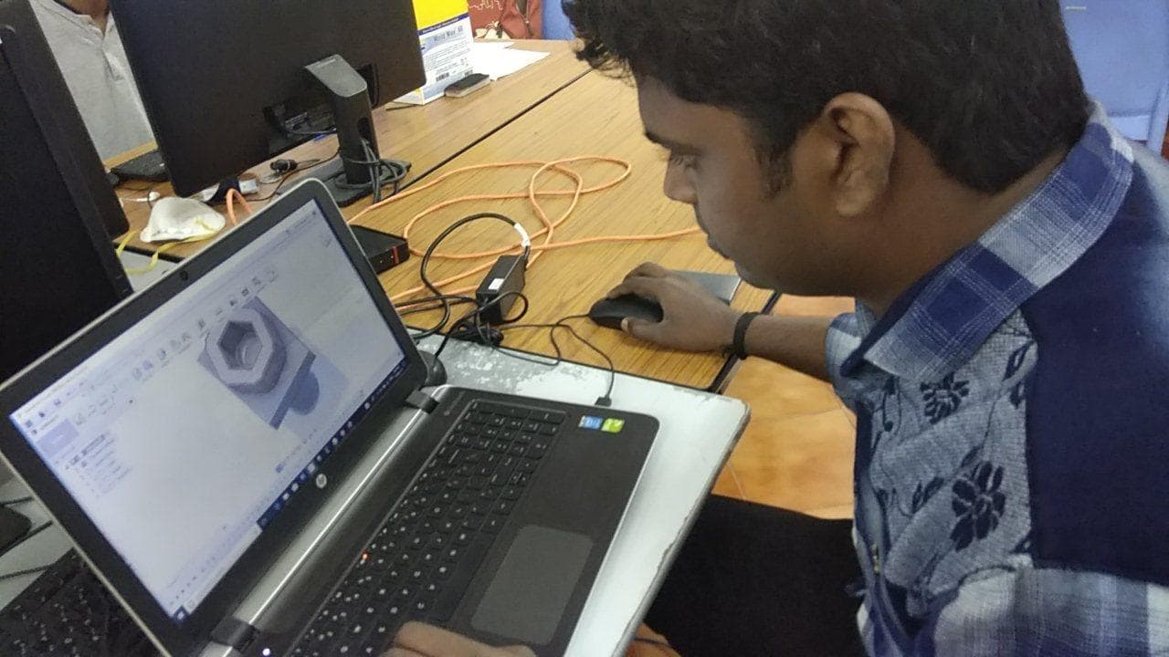
Now we were keen to make the basic arrangement and amith,aby and me decided to draw and print the parts in 3D.Amith started drawing in fusion 360 while I helped him with the measurements.
After designing we printed the parts in dimension which took more than 12 hours to get completed.
3D drawing in Fusion
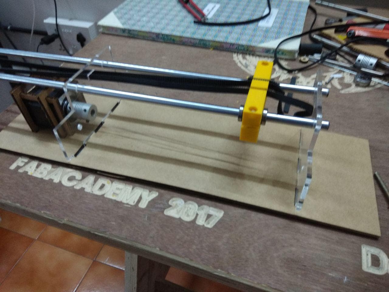
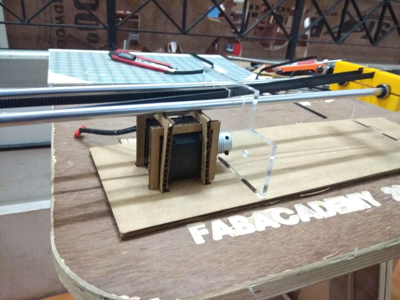
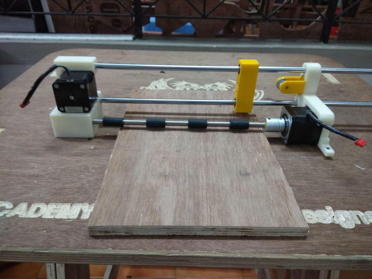
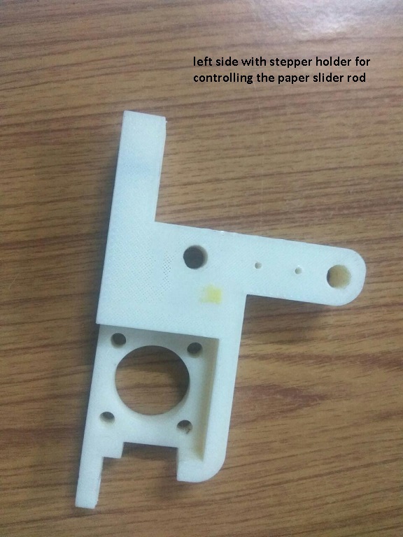
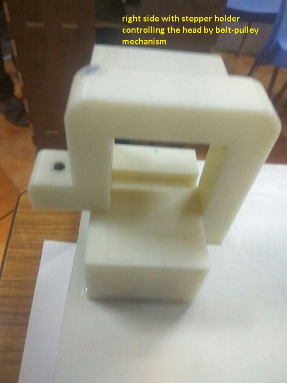
The first week is almost getting completed and the next day we took the 3d printed parts and started the assembling.The different 3D printed parts are shown below
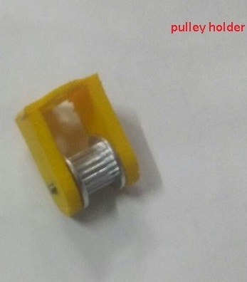
(from left to right):right side,left side with stepper holder,pulley arrangement designed by akhil which was later fixed to the side
ASSEMBLING THE PARTS
So after printing the 3D printed parts,we have started to assemble them,I and abhilash were looking after the belt and pulley connections while
others did the part arrangements.After this we used scrap plywood and cut them in size for fitting the base.
machine at the end of first week
THE SOLENOID HUNT-designing of solenoid attatchment with needle
It took a week for the solenoid to arrive,we were unaware of the force of the solenoid at the beginning,it was our instructor yadhu who
told us that he doubt wheather the solenoid has enough force to pierce holes.We were planning to use normal A4 size paper and a nail or a bit attached to it to piere the hole.
Three to four days we were running after the solenoid.Aby and akhil even planned to use the servo motor insted of solenoid,abhilash was trying to make a solenoid,akhila was trying a thin
alternative for A4 paper and she found out butter paper,while I was trying different nails and bits with the solenoid,designing the solenoid cap and testing it to find wheather we could get the result.
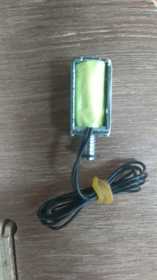
The first solenoid we purchased
We had purchased two solenoids and while testing we could find that using one solenois is a difficult task as it is not able to pull itself back after piercing the hole.We however
purchased two solenoids and I had made a modification to the design and build a 3D plate at top so that we could use 2 Solenoids to drive the needle.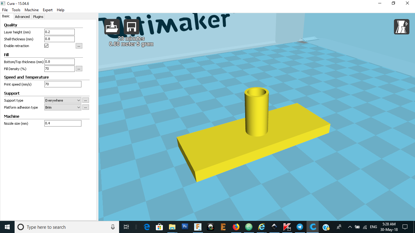
the solenoid attatchment model
While testing it was also unsuccessfull.By the time our instructor yadu had ordered a high capacity solenoid and it worked fine while testing.It could even pierce two A4 sheets
thickness.So again I was on the designing chair and designed a cap to fit the solenoid and needle.
designign of the solenoid attatchment
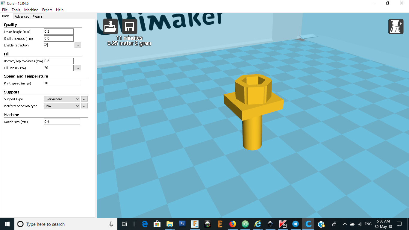
the new solenoid attatchment model
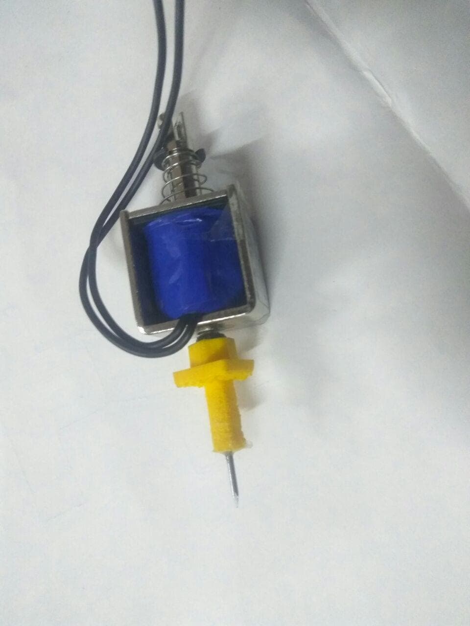
the new solenoid with the attatchment
By the time everything got fixed we realised that we are running out of time and so decided to use customs boards for automation.We decided to use A4988 Stepper Driver,Ramps14 and Arduino Mega for
automation of our printer.
CONTINUATION ON MACHINE DESIGN WEEK