ECHO-HELLO WORLD BOARD
TASKS TO DO-Use the test equipment in your lab to observe the operation of a microcontroller circuit board.
Redraw the echo hello-world board, add a button and LED with resistor ,check the design rules,
make it, and test it.
This is the second week of electronics in our Fab journey.This week mainly concentrates on designing and milling of PCB.We have to redraw the echo hello world board and make a design modification by adding a switch and led to it,mill our board and test the board.These much does this weeks assignment.
PCB DESIGNING-AUTODESK EAGLE
For designing the PCB I have used the autodesk EAGLE software which was recommended by our Instructor to start with.So the first task was to Install Eagle.

WORKFLOW IN EAGLE
So the workflow for designing in Eagle is as follows:
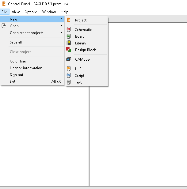
1)Create a project in the Control panel window.
2)Design the schematic diagram of our circuit.
3)ERC(Electrical Rule Check) to find any errors in the design.
4)Switching to board option to design the board.Arranging the components
5)Routing the path and connections.(auto as well as manual routing is available).
6)DRC(design rule check).
7)Exporting the files as .png for milling.
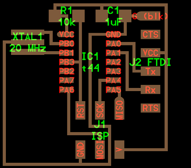
Schematic Sketch
For starting with our PCB design at first we have to open EAGLE,and create a project
in the control panel window.In that project the next is to create a schematic diagram.
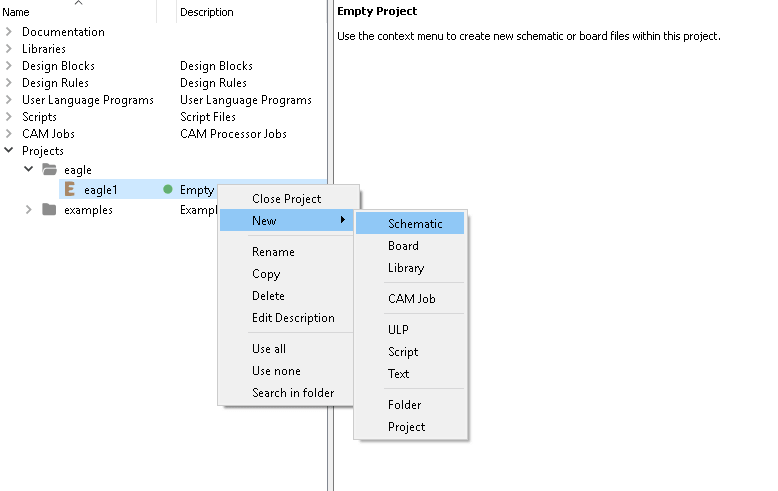
Now a shematic window opens where we have to draw the schematic diagram.Usually it will
have a white background.We also have ana option to change the background to black or colour by going to
options>user interface
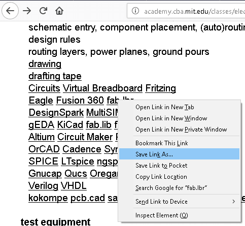
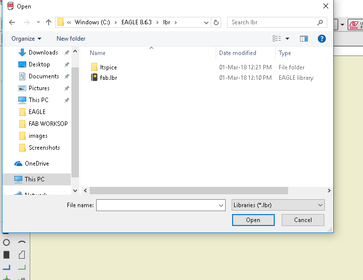
To start with our drawing we need the fab library which will not be available in the newly installed Eagle.We have to add the fab library
to the Eagles library.We have to download the fab.lbr from the link in electronics design lecture and
add paste it inside Eagle library and load it from the library manager.
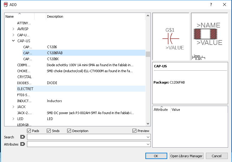
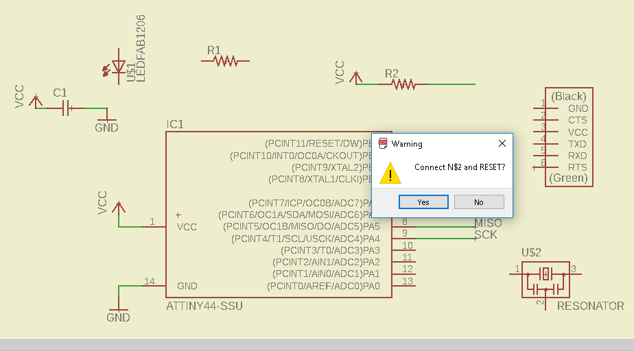
Now I have started with my schematic sketch.The basic steps is to add the components by using the command add in the
command line.Add the components.Give the proper connections.We can use Net tool to connect the components.
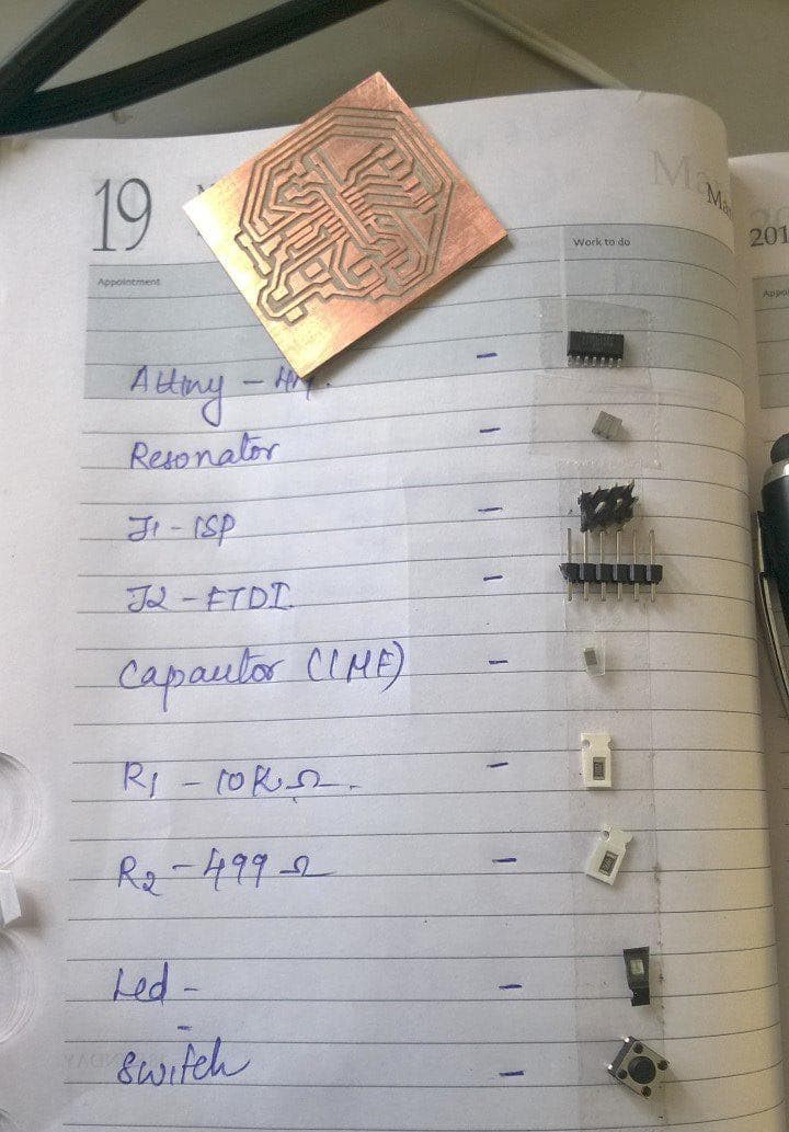
Components Required
ATtiny44
20mhz resonator
6mm Switch Omrom
AVR ISP SMD header for programming the board
FTDI SMD header powers the board and allows it to speak to the computer
10 kilo-ohm resistor
499 ohm resistor
1 microfarad capacitor
smd led-1 NO
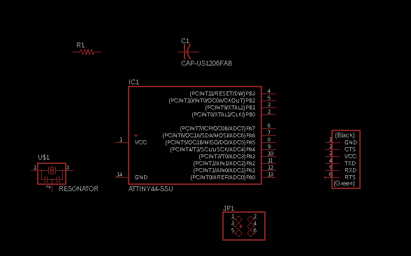
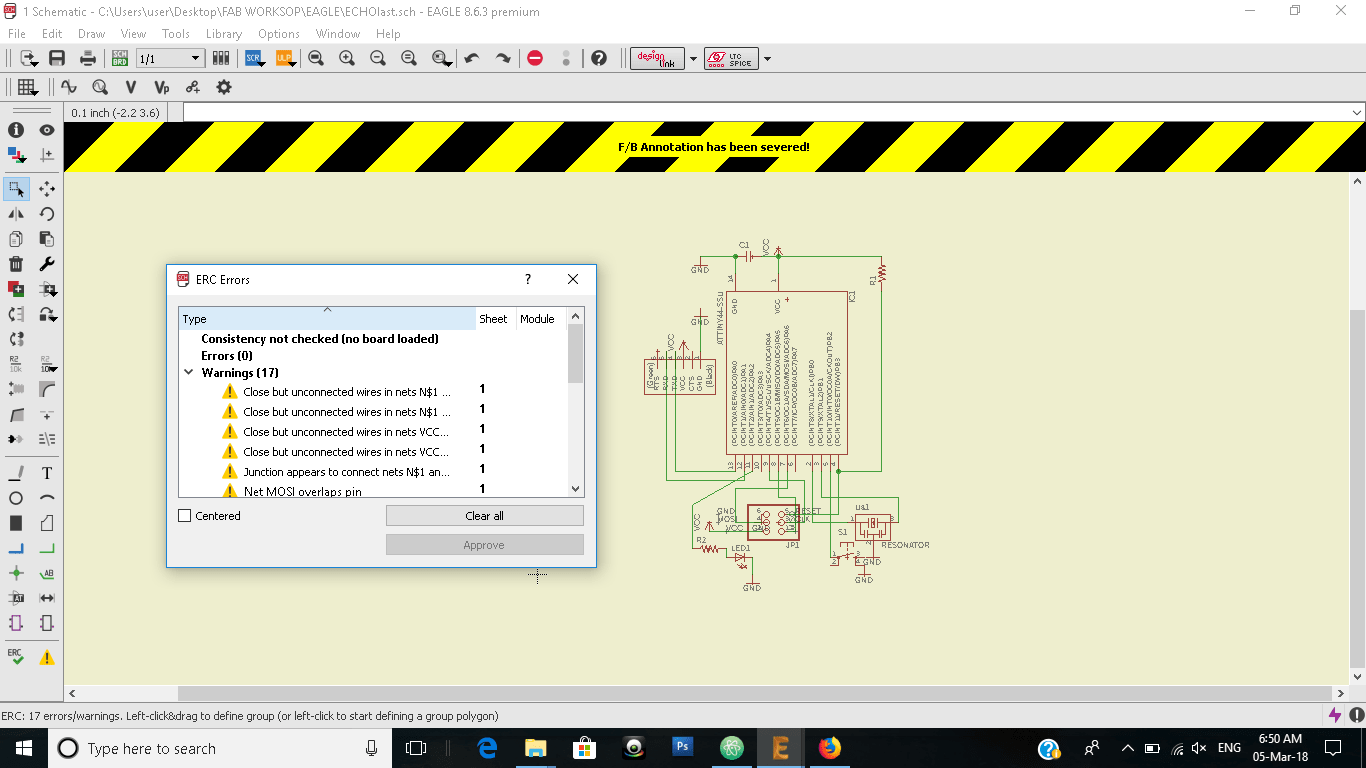
I have a lot of errors at the beginning proving I am a beginner.At first i have drawn the schematic without giving a connection for VCC and ground.
After redrawing the schematic with Connection for VCC and GND my schematic looked like a mess,and After checking with ERC,I found out that for some of my components only one side shows the conncetion. I was totally exhausted sitting and debugging and decided to redraw the schematic sketch.
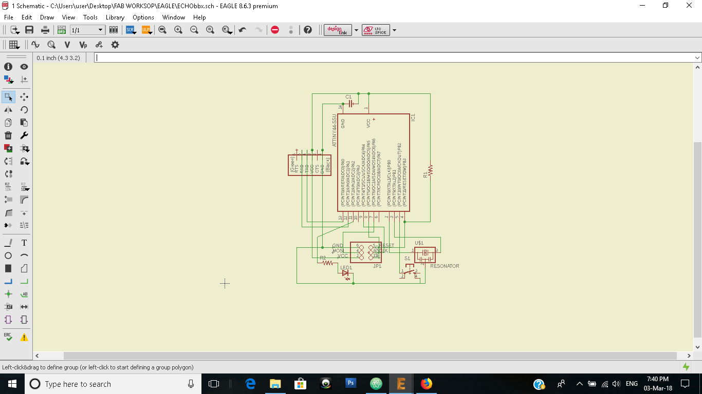
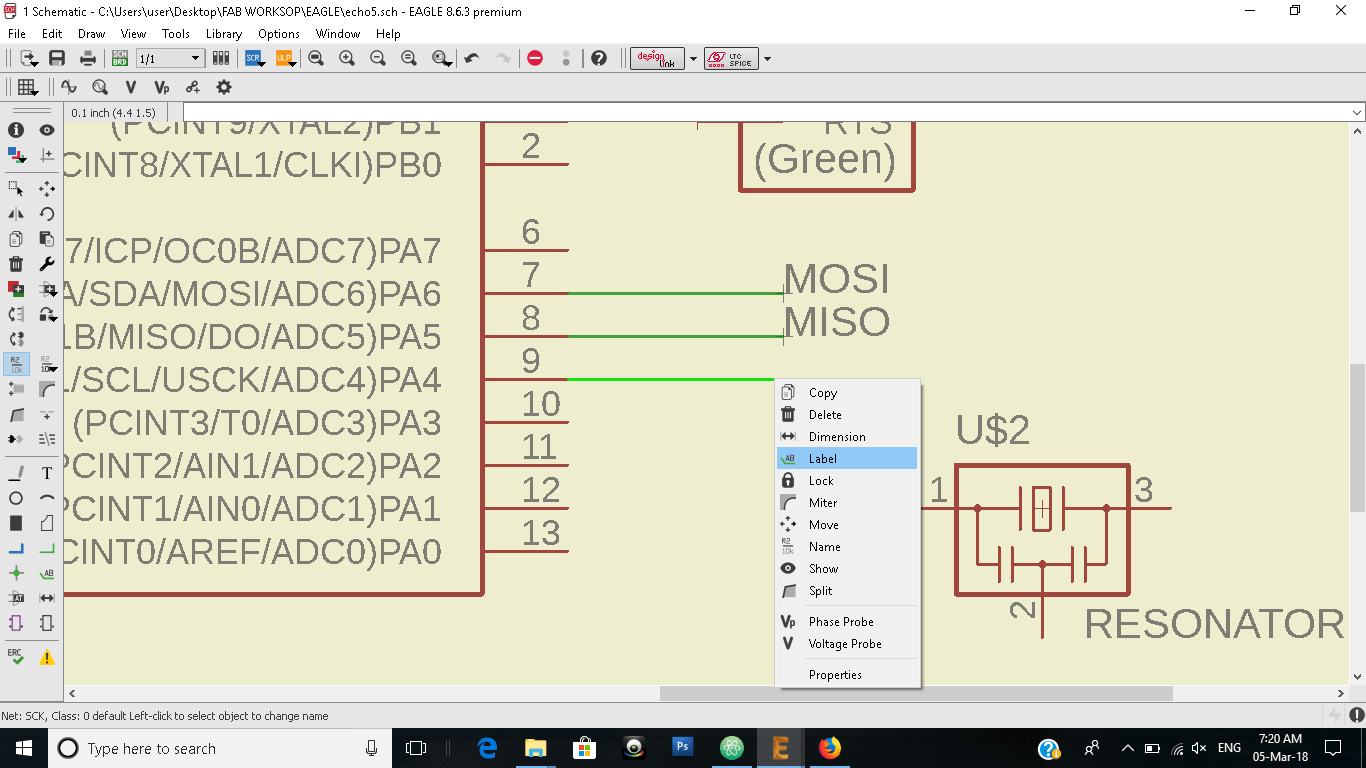
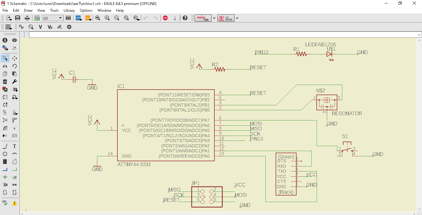
This time I decided to not to tangle the connections,so used another method of connecting the components by using name and label options.This visually itself we can debug the errors without an ERC check.This time the check was proper and I went on for designing the Board.
Board Designing
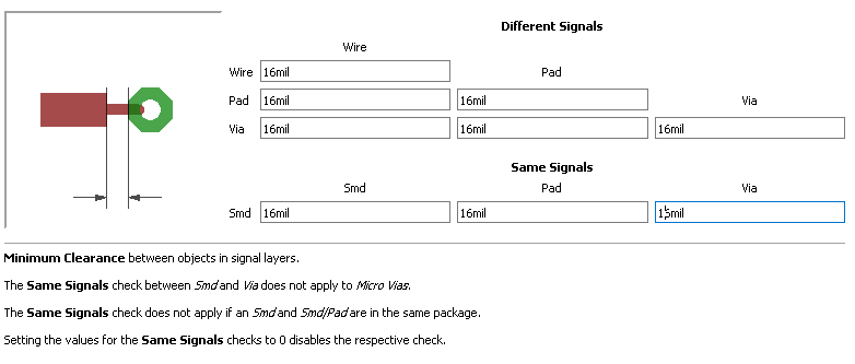
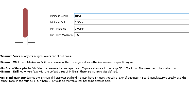
After completing the sketch we have to give switch to board option,where we allign the components and route the connections So in this window we have to allign the components as if all the connections will pass through and route the connections according to the design rules. In the design rules (edit > design rules) we have to give the clearance for the milling and size of the traces.We have given the clearance as 16 mil and size of trace as18 mil.
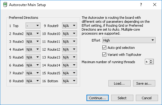
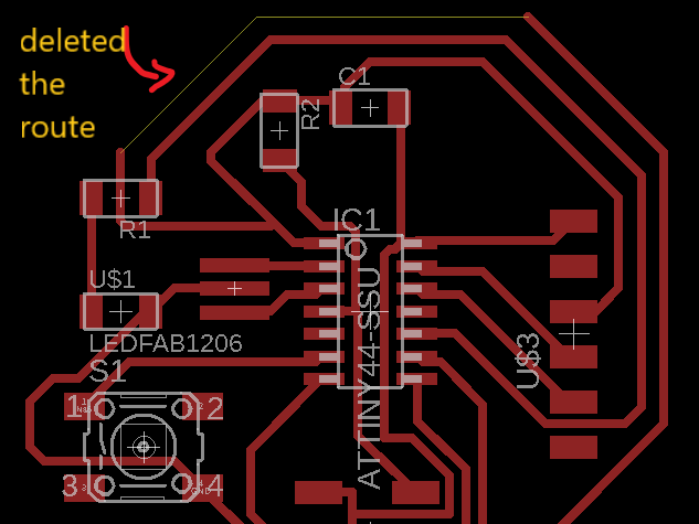
After that I started to route my boards connections.In the autorouter window,we have to select the layer of PCB to route and the precision for routing.Since all the components are in the top layer deactivate the bottom layer by choosing not applicable and go for routing.Routing shows intersecting connections and we have to clear that and give proper space for connections to pass.
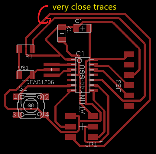
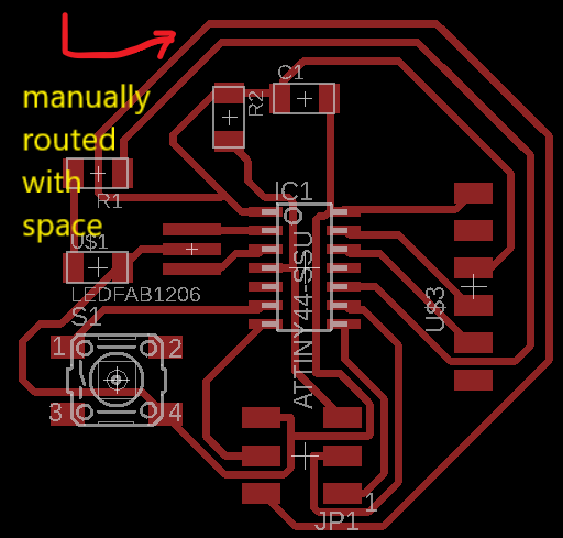
Another mistake I made here was that I alligned my components very close to each other so that it was difficult for routing. Realising this I gave space and autorouted my Board and I got only one route of four which is 100.others were around 90.I selected that route and manually routed some 90 degree connections,checked DRC and checked with fab modules the traces for milling.
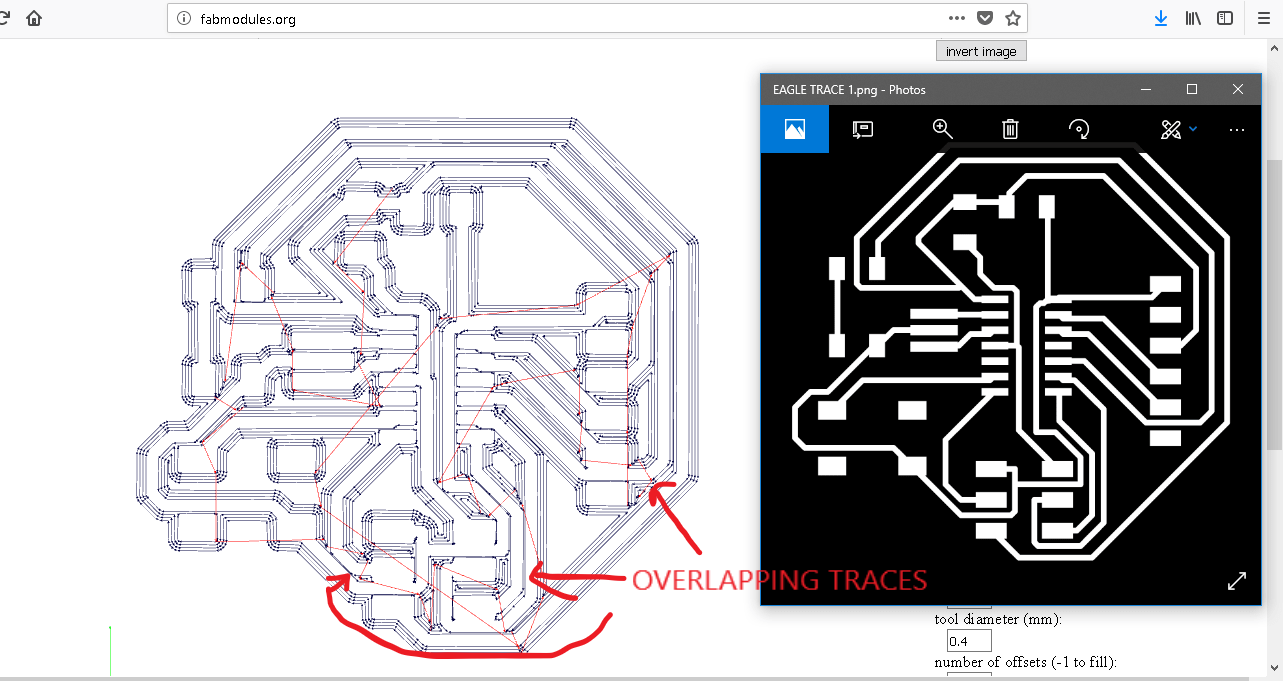
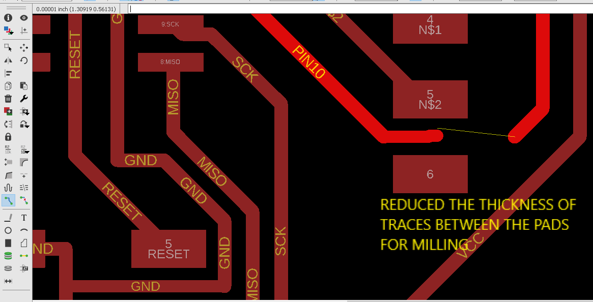
I found out that there was some overlapping in the milling and so I went again to the board and reduced thickness of the path which was overlapping and again checked DRC, this time it showed some warnings because of different size connections and was ignored and went on to milling.
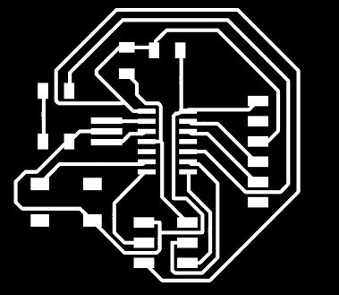
For the milling process we have to export the file as image(.png).Go to layers and
select the layers for traces as well as cutting and export it as monochrome.
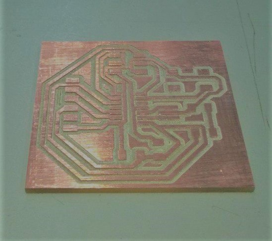
Making the PCB
For the PCB production process I used Roland Modella MDX-20 at our lab.
For milling the traces- 1/64th inch bit is used
For cutting - 1/32 nd inch bit is used
Fabmodules is used as the print manager
The setting up of modella MDX20 and using is explained in my Electronics production week
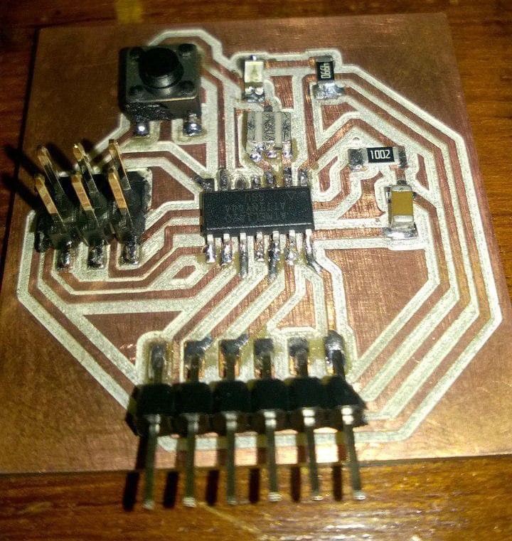
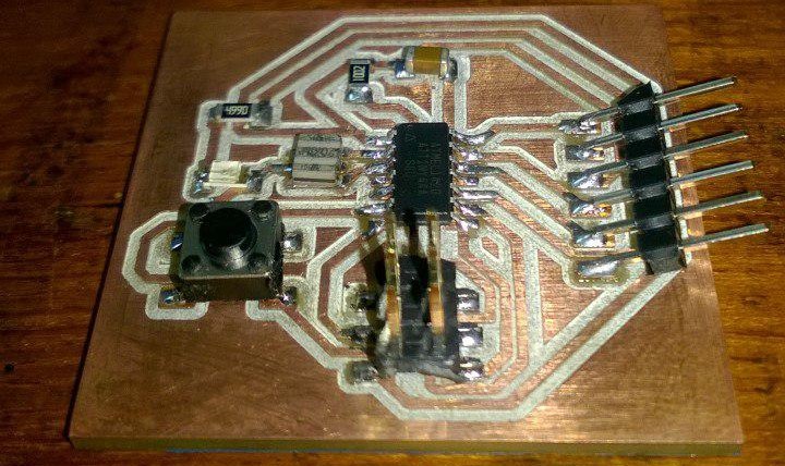
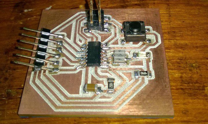
Soldering the components
This time soldering was very easy compared to the last week.The ATtiny44 was soldered first and then the rest of the components.The only time
consuming component was the resonator.The soldering was ok and the connections were proper when I checked with the multimeter.
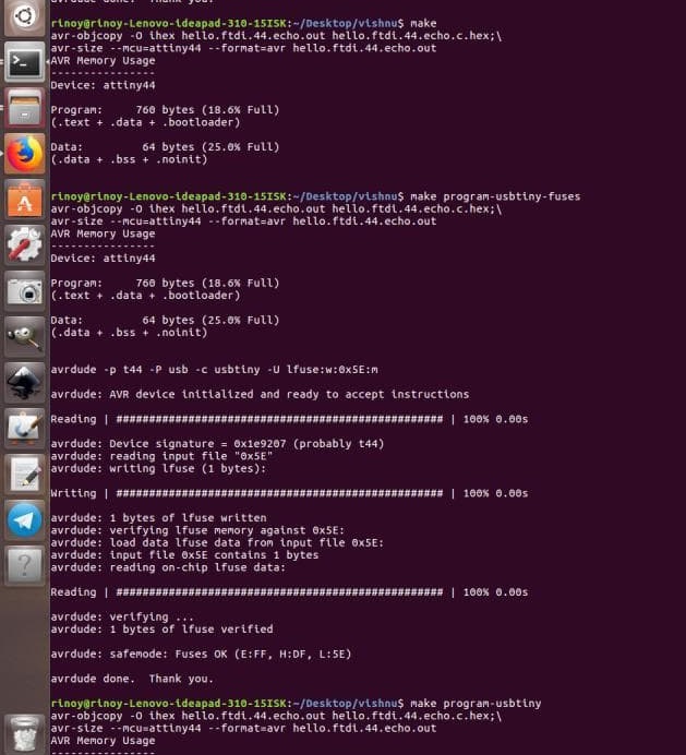
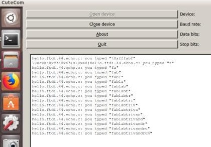
Programming my board
So the next step is to check my board wheather it is commuunicating with my ISP programmer and working as per the echo hello world program.For this we have to download the .c file and .makefile given in the lecture files.Rename .makefile to .makefile.Now the rest is to be done with linux.I used my freind Rinoys laptop for this.open the terminal and give the command make to create the hex file.Now make fuses and download cutecom to check the working of echoboard.connect the board wo the system with the USb serial port connector
Group Assignment
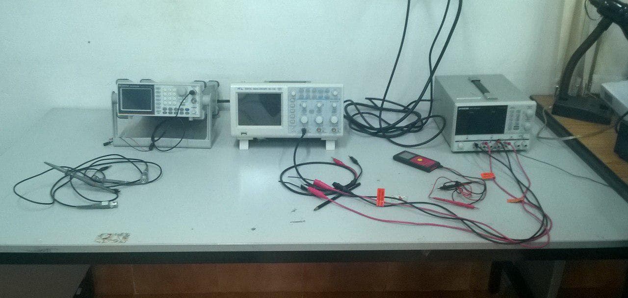
In group assignment we have to observe the operations of a microcontroller circuit board using the test
equipments available at our lab.The various test equipments available at our lab are:
1)multimeter
2)Digital oscilloscope
3)Arbitary fuction generator
We were given instructions and working examples on every machine and we have used multimeter and digital oscilloscope to test our
boards.
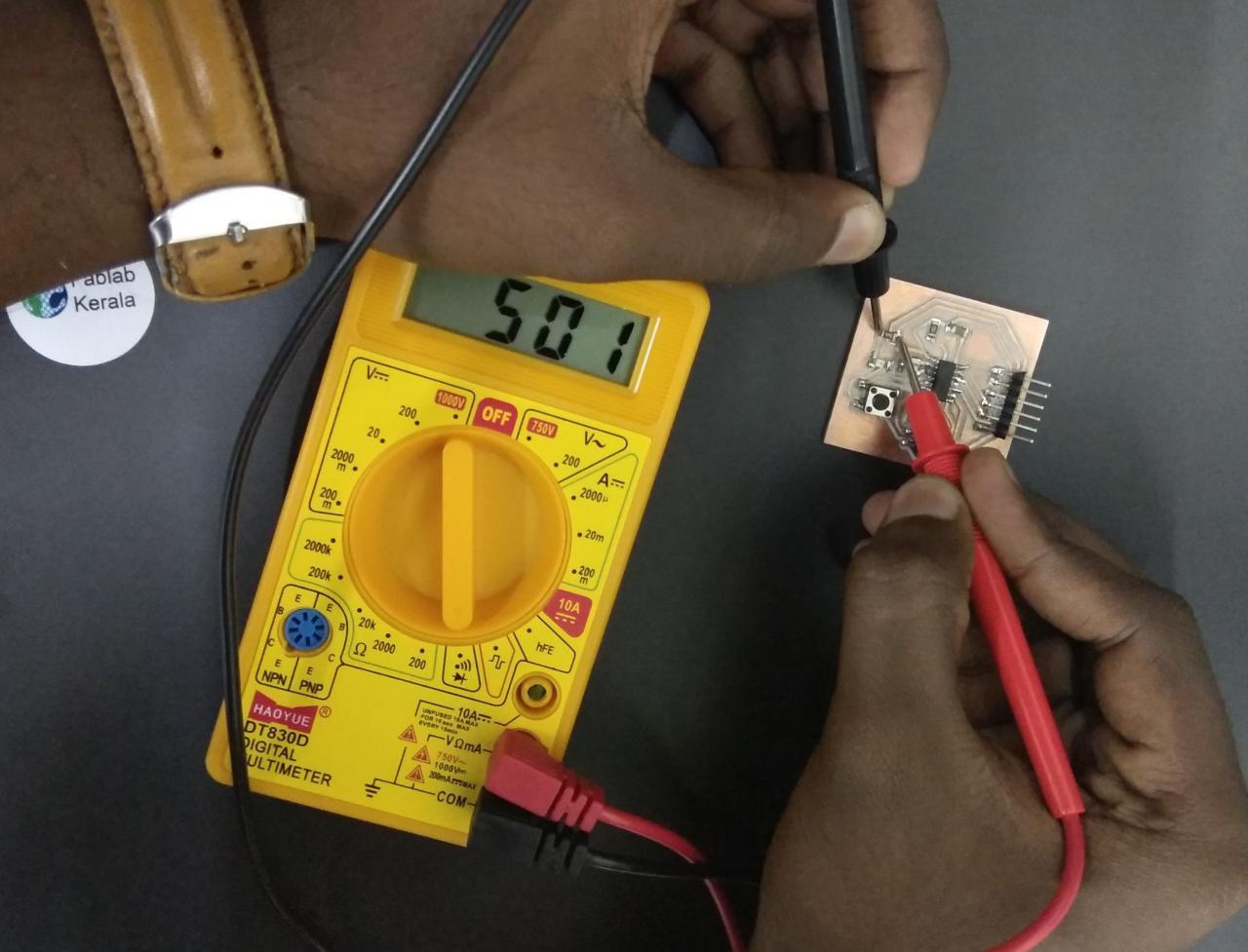
Multimeter-multimeter is used to check the continuity of conneections in our board.We have used our own boards to perform the task.
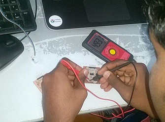
Multimeter shows this value for 499 ohm resistor.this shows the tolerance value of the resistor.
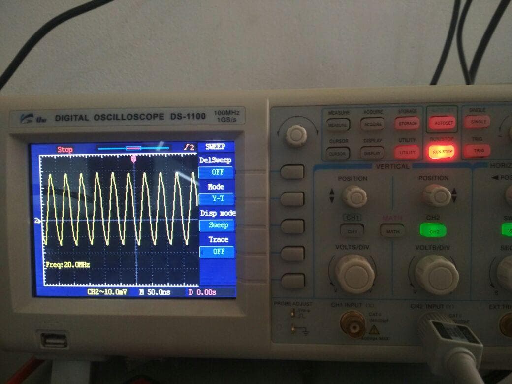
Digital oscilloscope is a device used to store and analyse the signals.We have used our board to check the frequency generated by the
resonator we fixed on our board.
Summary
This week was an ok week for me.As a beginner I took more time to understand things.I was exhausted
sitting for a full day to create the sktech of the board but the PCB production,soldering and programming was easy.