Week08 - Computer-Controlled Machining
1-Design Ideas
For this week's Assignment i had lots of ideas and just one plywood board to work and test with. The plywood is Birch. 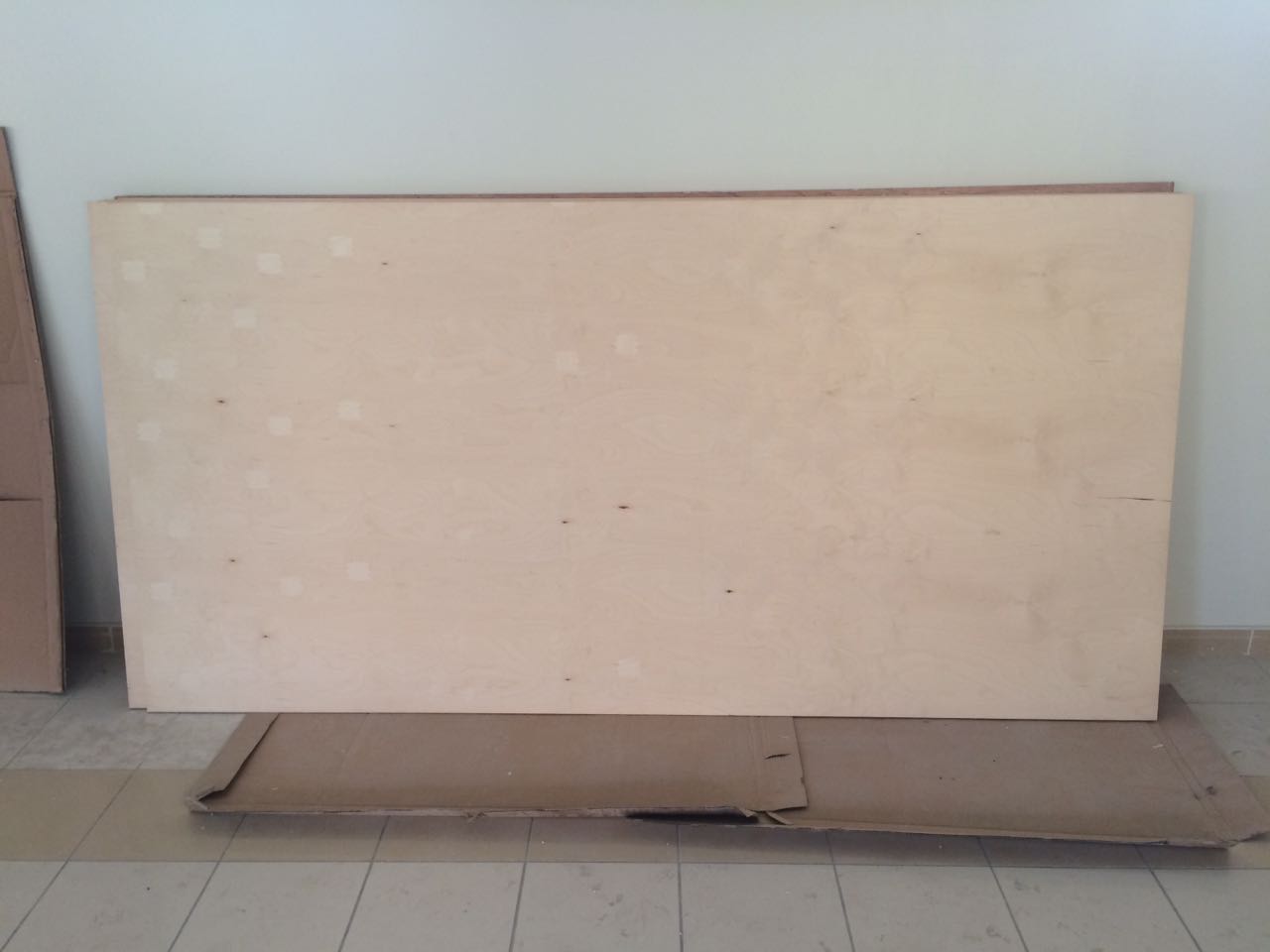
After designing a thing or two, i decided i wanted to make wood only joints and press fit the whole thing, that meant giving up on a design, and giving up on designs quickly escalated as each time i finish i don't seem to like it anymore and i start over. 
4 Designs later I settled on something, i felt it was the one, I am gonna make it. 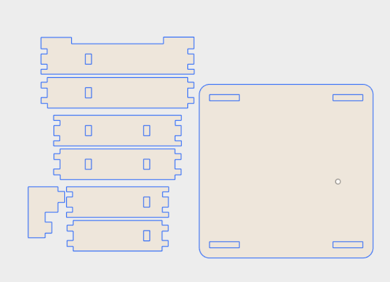
This took me a while to design on fusion, i was still learning at the time. The design is pretty simple, these are the sketch tools i used. 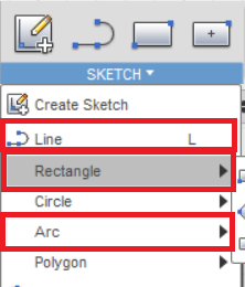
Arc,Rectangle and Line tool, that's all you need for this, below is a screenshot of where all of them meet together in the sketch piece. more about sketching on Week04. 
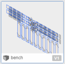
Now i feel much more confident with my skills, this above is the prototype design it is 4 times smaller than the real thing. The design looks very simple but it took me time to understand how everything fits together, a lot of imagination was involved.The above design is almost entirely parametric 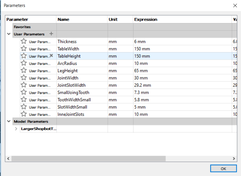
but at this week i didn't understand how to parametricly design something perfectly, you see when i tried to scale everything using the parametrics window, everything was ruined, now i know how to fix things like that. More about this problem at laser cutting week 4 link below. I laser cut the design above using "Universal Laser Systems" laser cutter. More about Laser cutting and Designing parametrically on Fusion at Week04. 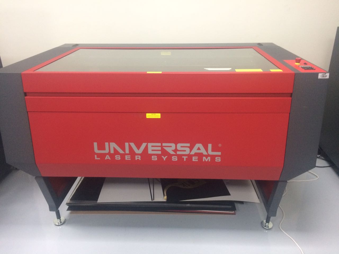
Exported the sketch to DXF, printed using the universal laser systems cutter and then assembled, more about that also on Week04 link above. 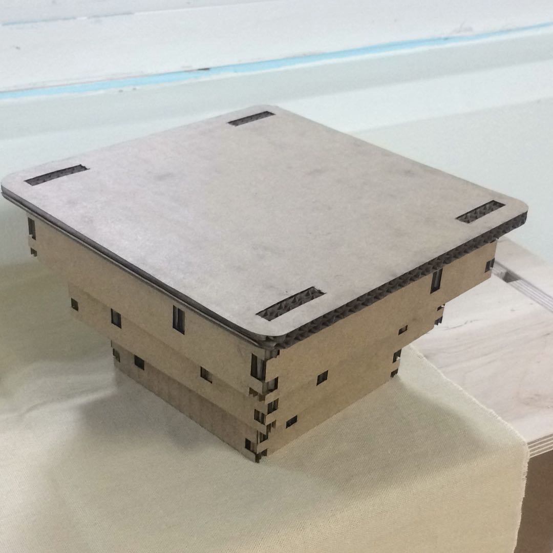
This is the result above, this result was using 6mm cardboard. I also created a larger design. The larger design is meant to be used on the 12mm thick plywood board, to be milled on the shopbot. 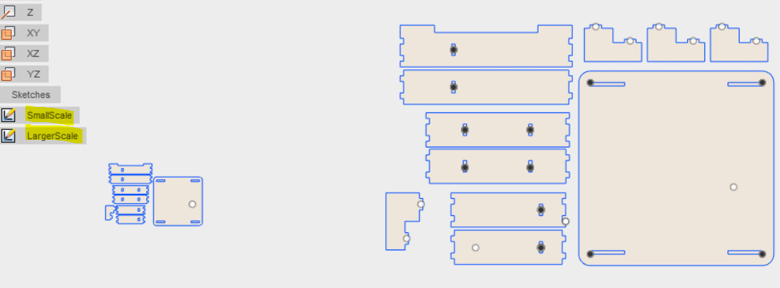
Download f3d fusion file here. 2-VCarveI will explain the process of using VCarve below. 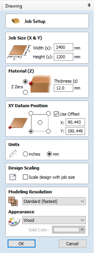
When you create a new VCarve file, the first thing you need to do is to give the software the dimensions of the board you are cutting. In our case the size is 2400x1200mm, then the thickness of the material in our case 12mm. the appearance to wood. After this step, you go to this icon. 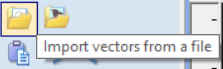
This allows you to import your dxf, file and that is what i did, i saved my fusion sketch as a dxf and then imported it here. So great now your design is in VCarve. The next step is to use this tool called "Create Fillets". 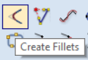
This will show this window. 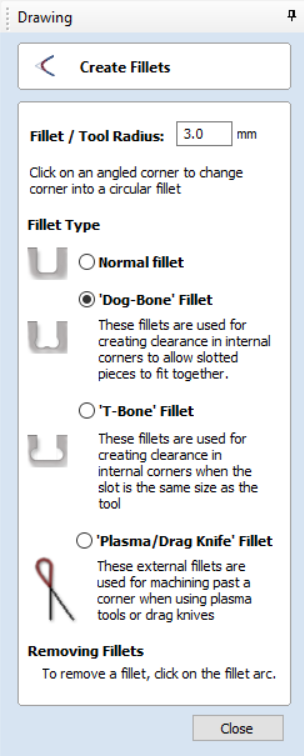
The tool i am using is 6mm diameter, so 3mm is the tool radius. I used the dog-bone because i wanted to fit pieces easier. 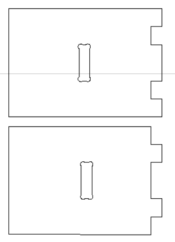
I used the dog-bone in the above picture only in the internal slot. -Problem Here-I had a problem at this point, this piece is not connected for some reason, the shopbot will ignore this piece when you calculate the toolpath and that is a problem! 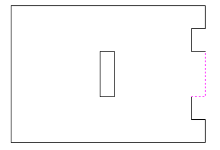
See how when i clicked on that side, it selected only 2 vector lines. To fix this I used joining tools. 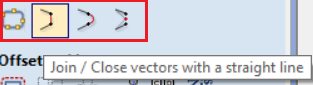
You can use the "Join open Vectors" Icon first one to the left. and i tried joining with a straight line, they all work depending on what you need, they join lines for you. once you are done joining, your piece should be one piece only like this. 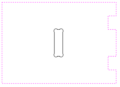
You now have this design ready so far. Problem 2, I chose not to use dog-bones on the right side slots, i actually forgot some and meant to not use dog-bone on some, anyway everything was solved by force! 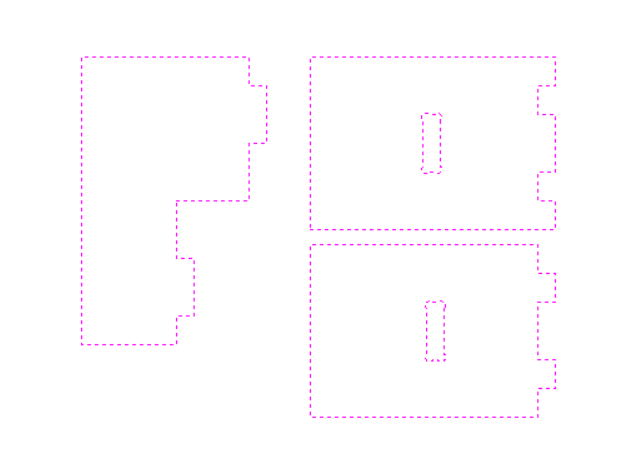
-ScrewsBefore we do anything, screws are important to stabilize the plywood you are cutting, having a couple of screws around your piece is recommended, however if you are gonna use screws, it is better to have the exact location of the screws on the VCarve file, so you know to keep away from them. To do that, you just create circles with this tool. 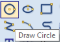
This will show this window here. 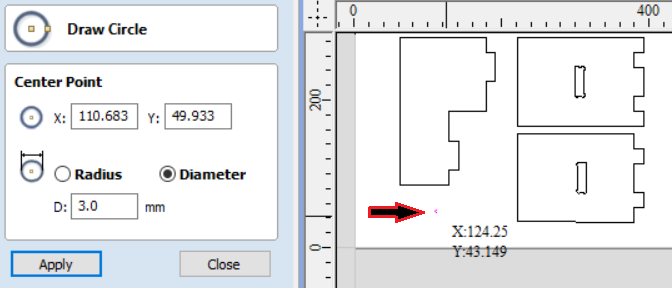
We just want to mark the plywood with few millimeters deep holes, that will help us screwing the plywood too. The tool has 6mm diameter, if you choose 3mm as the circle diameter, it doesn't matter because the tool will drill 6mm anyway, i feel it is better if i used 6mm instead, but i already worked on this. As you see the arrow, the you just move the mouse on the position you like and create the circle by clicking the left mouse button, you will get the 3mm circle in that position. At this stage we are ready to start calculating the tool paths. There is a Toolpaths window on the right. 
We mostly used these 2 for cutting using the shopbot, the marked left icon is called "Profile Toolpath" the other is "Drilling Toolpath" let's start with the drilling first. 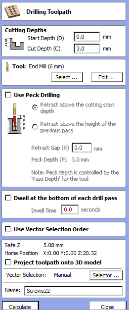
We need to make sure that we are just marking the screw positions on the plywood, so a cut depth of 3mm is just fine. Then we need to choose our milling tool, to do that we select it from a database already created, or if the tool you are using is not there you just add it from this window below. 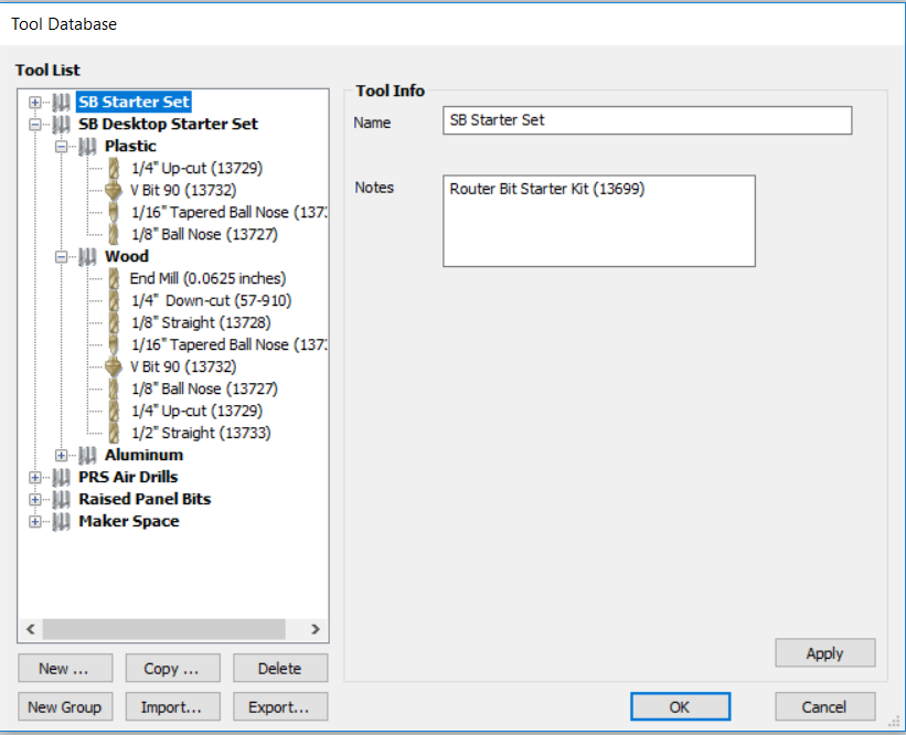
When you create/edit a milling tool you get this window. 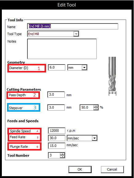
Above numbers are actually what i used for the 6mm end mill bit. Red1: This is the diameter of the milling bit. 
Red4: The spindle speed is the speed of the tool turning, our lab already tested 12000 RPM and it was great on the plywood i was gonna cut, so i kept the setting. This is it, you can now click on the calculate button after you give it a name to tell it apart. -Profile Toolpath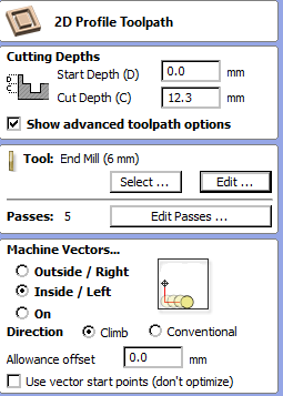
As you remember, our plywood thickness is 12mm, i chose 12.3mm cutting depth, why did i go over? well that is because we want to make sure it goes all the way and cuts it, we are not afraid anything breaks because we do have another plywood sheet under it, so it will just etch the below surface and will give us a clean cut hopefully :D. 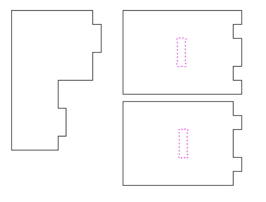
Again click the calculate button and give it a meaningful name to tell it apart. Then we select the outside traces, and do the same process steps except Outside instead. For the outside, you need to add tabs, tabs are basically tiny places where the milling bit will not cut while going along the cutting path, this is to ensure the piece doesn't move when cutting. 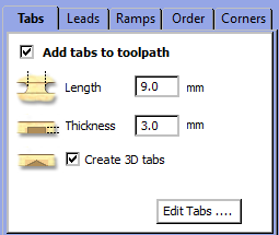
The length of the tab, is like the width of it, how wide you want it to be, i chose 9mm because my pieces are big and i want that much support from tabs to hold my piece, you also need to choose the thickness, i chose 3mm because i want to easily be able to cut it using a Chisel tool. 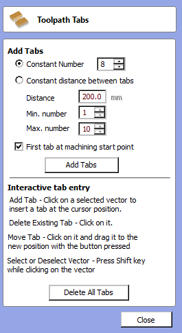
This will automatically create tabs on i would say random locations, but they aren't really random, you choose the number of tabs per piece, i chose 8 here, then i clicked add tabs. this is what it looks like. 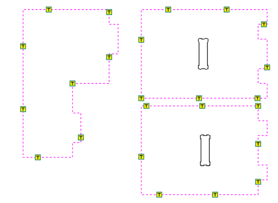
Each square with a 'T' letter is a tab, I prefer not to have tabs on where pieces connect together, this is because i don't want to sand them off later, so i move tabs manually by dragging them with the mouse button. Note you can only drag tabs in the edit mode. 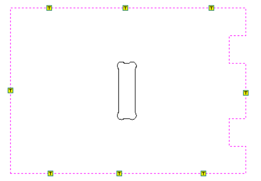
This is a great example of where i prefer my tabs to be, not on corners i dislike corners. Then you are ready to calculate. 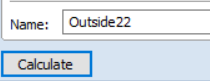
You can preview the how the actual pieces will look like if you click on the preview toolpath icon and the 3d view tab above. 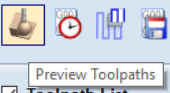
This will show you this window. 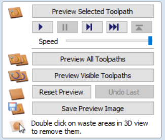
A good thing to check when previewing, is that your inside cuts are done first, it is a best practice to do that. to check which is gonna be cut first, you need to slow down the speed from the scroll bar above, then click preview all toolpaths. You will see something similar to below, but really slowly shaping 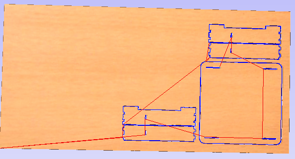
if you noticed it did the outside before the inside that means you need to move the inside toolpath calculation up in the toolpath list. 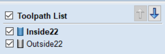
Then that is it, you need to create the shopbot file now. 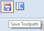
Clicking on the above icon will show this window. 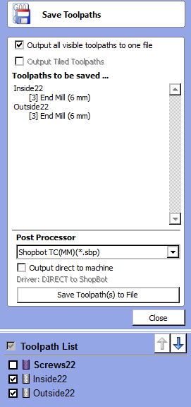
We always make sure to untick the "Output direct to machine" button, just to make sure that we did set the xyz zeros correctly and to double check some other things. Press Save toolpaths to file and you will get the shopbot file. -AdditionalYou can check how much time will the cut take by clicking on this icon. 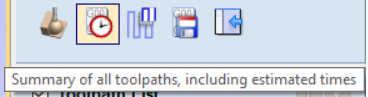
Then you will reach this window. 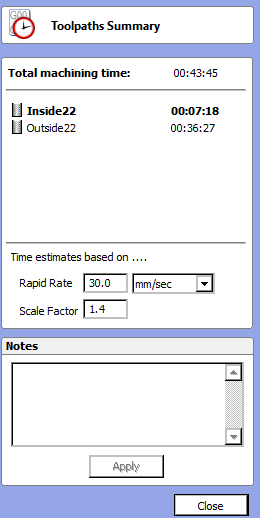
I dont need to explain this it is obvious, each toolpath calculation with it's time estimate. Note that this below is the actual shopbot table vcarve file, i only did calculate the top of it as it takes time and i didn't have much left, i just wanted to make sure everything was okay, anyway the below one has all parts they are just not that organized. Download the VCarve file here. 3-ShopBotAll i have to do now is to use the shopbot! 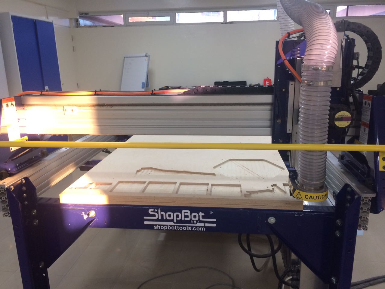
We now have the shopbot files ready, we need to start up the shopbot software and the shopbot first. Switch on the shopbot. 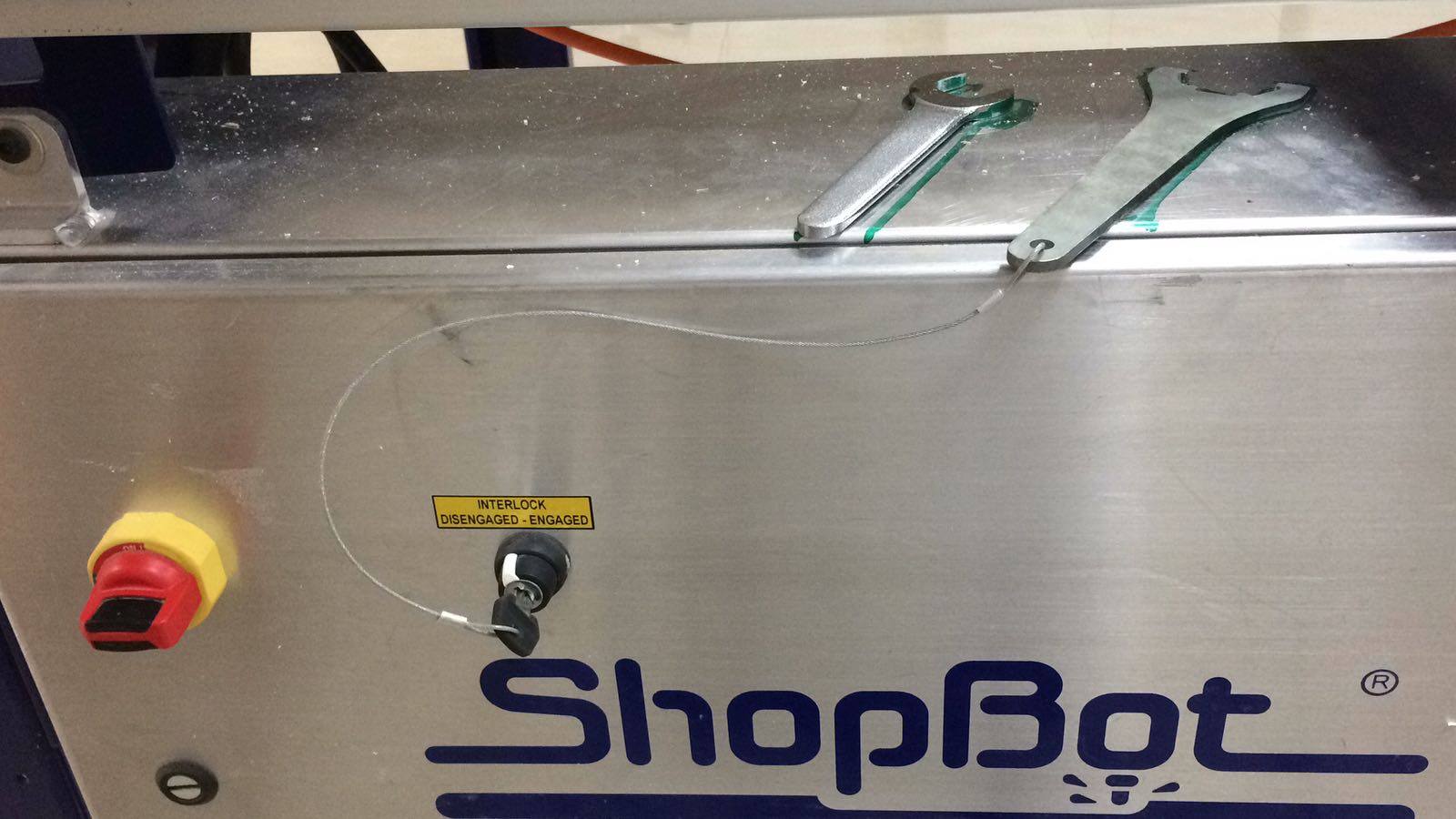
Open the Software. 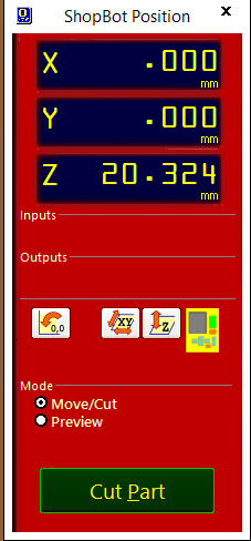
First thing you will notice is this popup window. 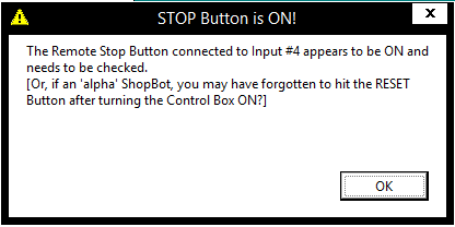
Now i dont know if this is just our machine or all shopbots are like this but we do have to click the stop button at least once and then make sure it goes up again, then we click the reset button, this will allow the software to connect to the shopbot. 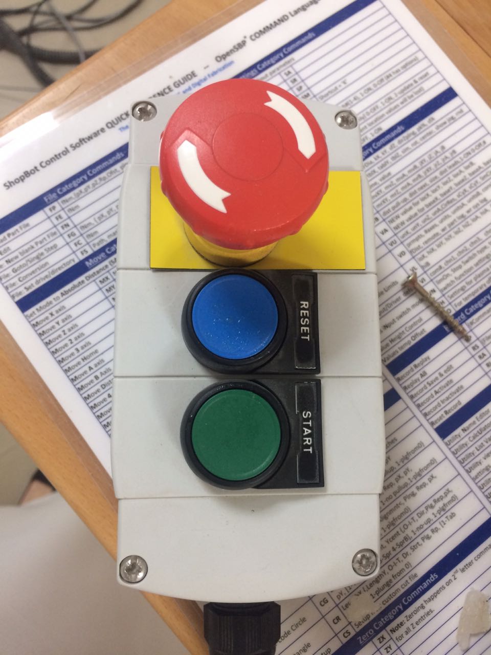
We use the yellow panel to the right to make sure the shopbot is indeed connected and we try to move it. 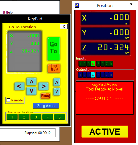
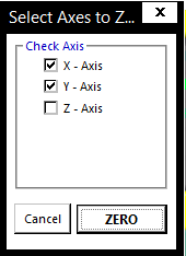
Great, now we need to reset the xyz and origin them to 0. Let's start with xy, first we go to bottom left corner this is when you are facing the switch. We manually find the tip of that corner and double check that it is indeed fine then origin. 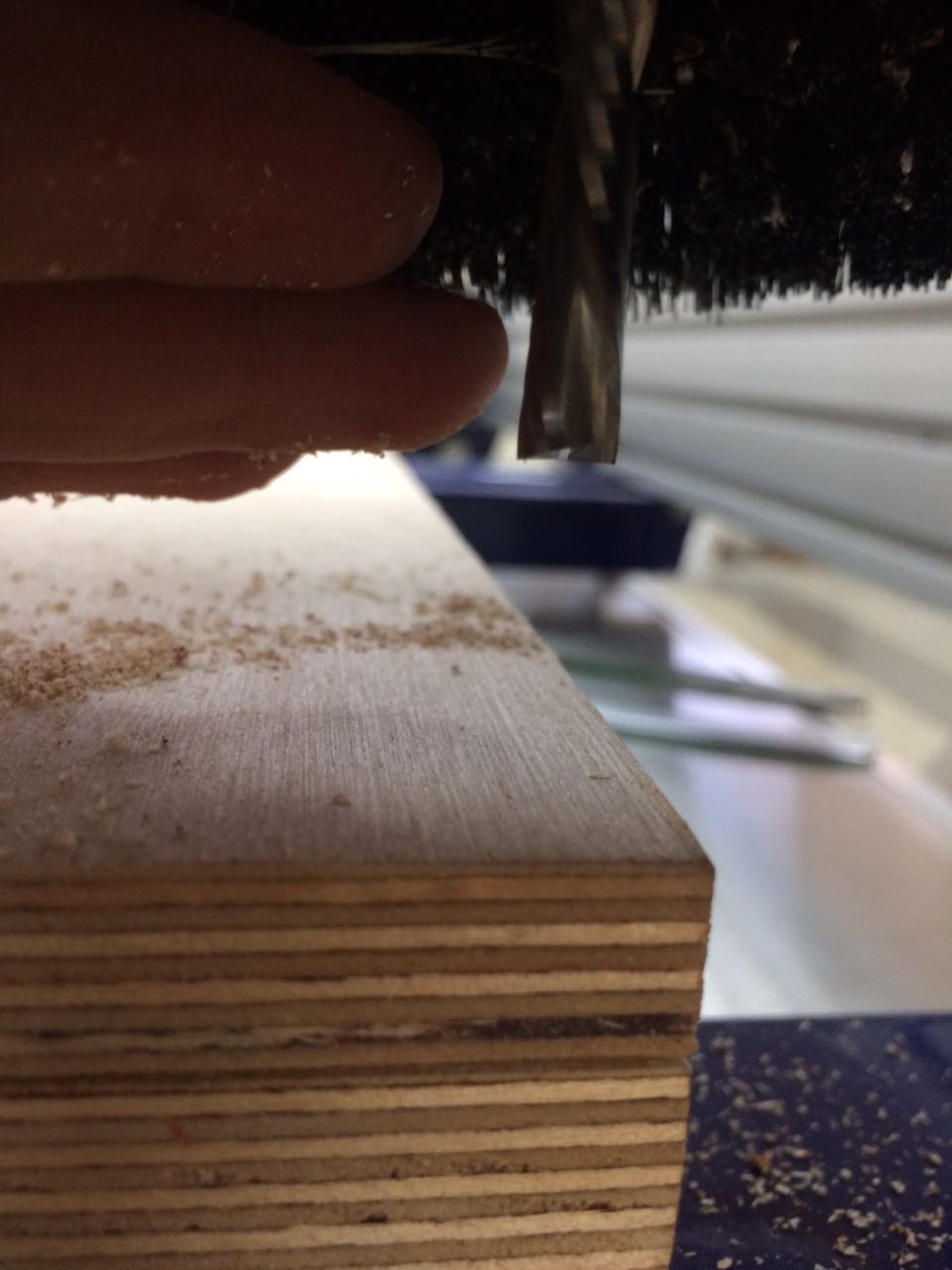
now we move the bit to a flat surface, it's better if that flat surface was closer to the cut but its not that important. Then we clip the clip to the metal chasi of the shopbot, and test if the software is detecting the plate touching the bit. 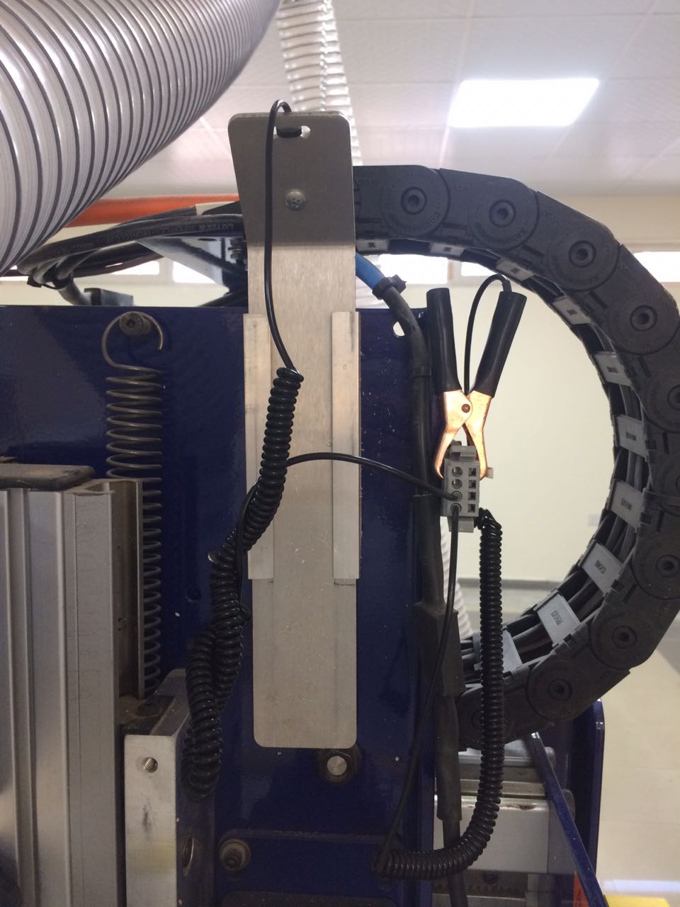
clipped clip. 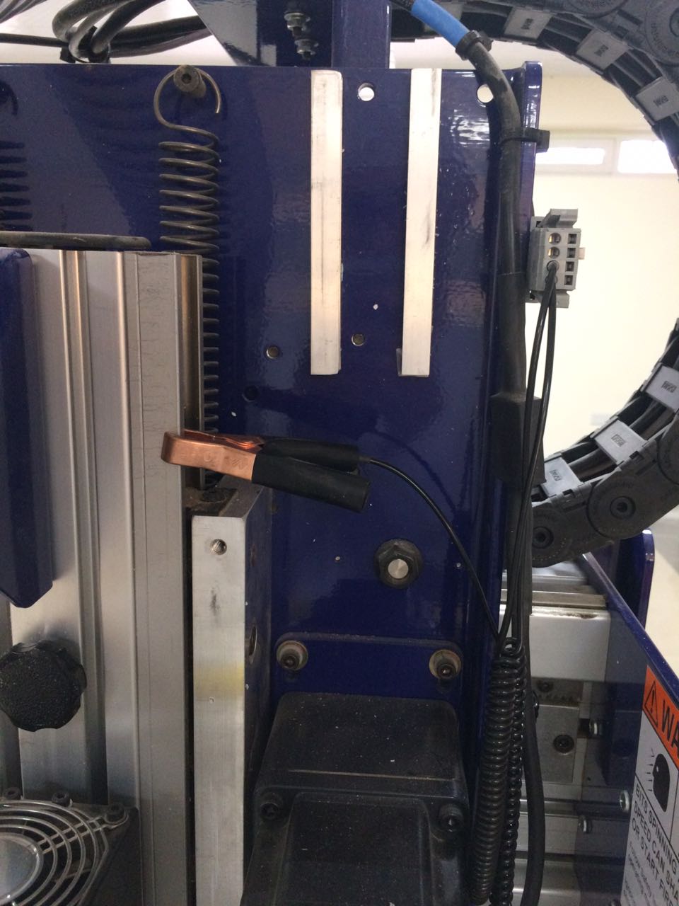
Testing if the software detects the plate. 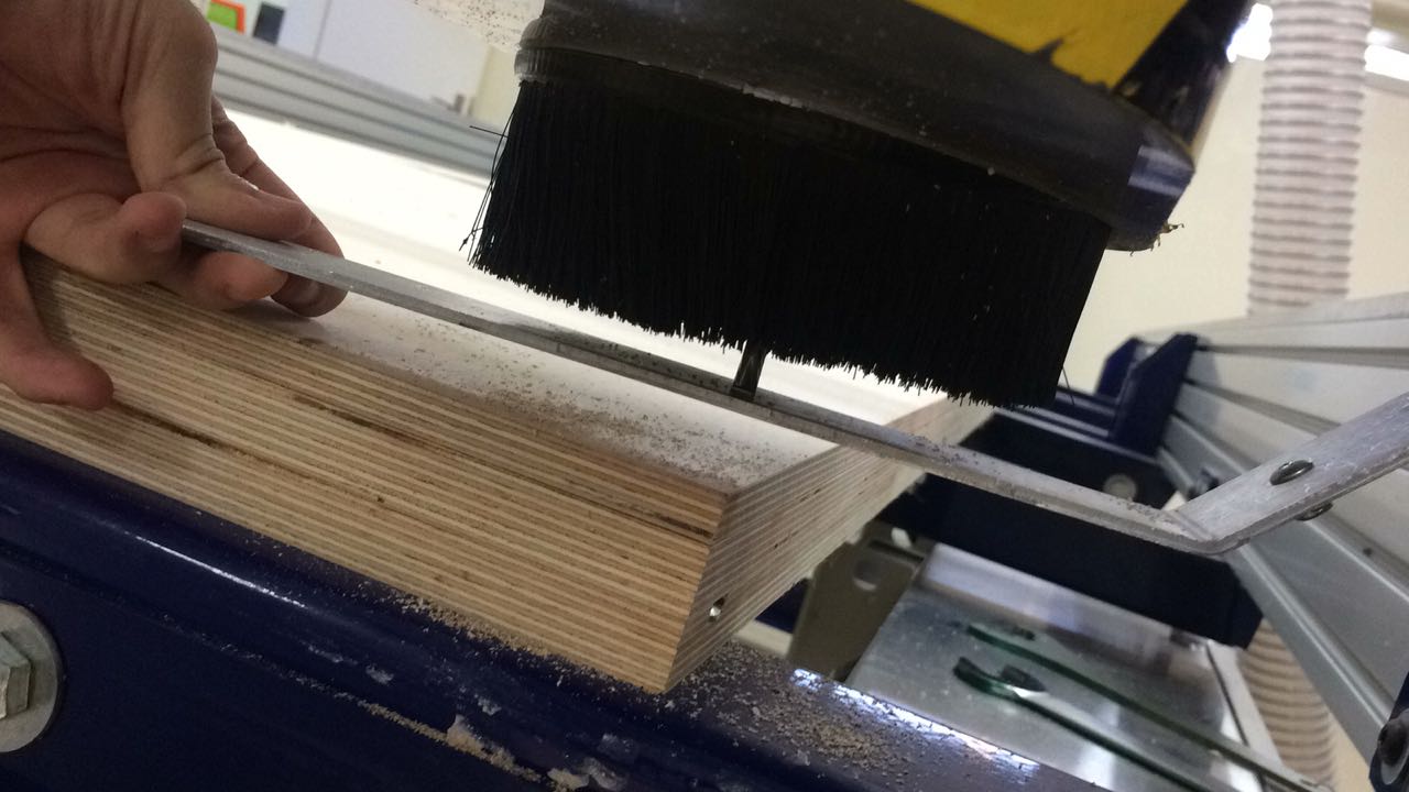
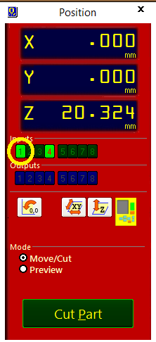
Great now we can begin zeroing by clicking this here. 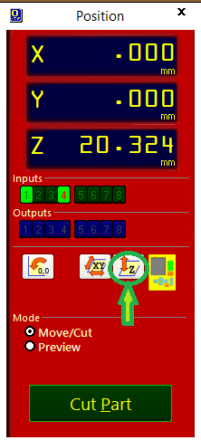
Done, now we can start the cut! First let's do the screw marks. You click cut and find your screws shopbot file, which by the way should not be with the inside/outside toolpaths, it should be separate because we need to stop after marking the screws. Click start. you will get this notification because the cut depth is 12.3 while the material thickness is 12, we just click ok because i explained above, then we press the start button and wait till the bit reaches max speed and then click ok.
Now we screw the screws into the holes using a drill. make sure that the head goes inside, or not too much out, few millimeters doesn't matter. 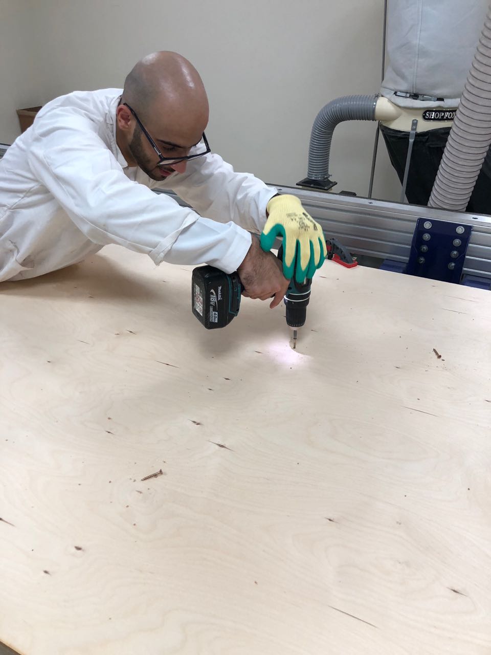
The same process goes for cutting the pieces, except it will take much longer, and you will be done with this 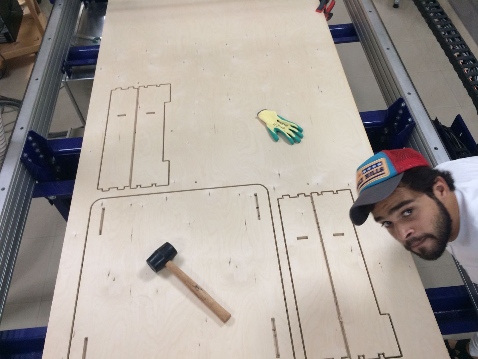
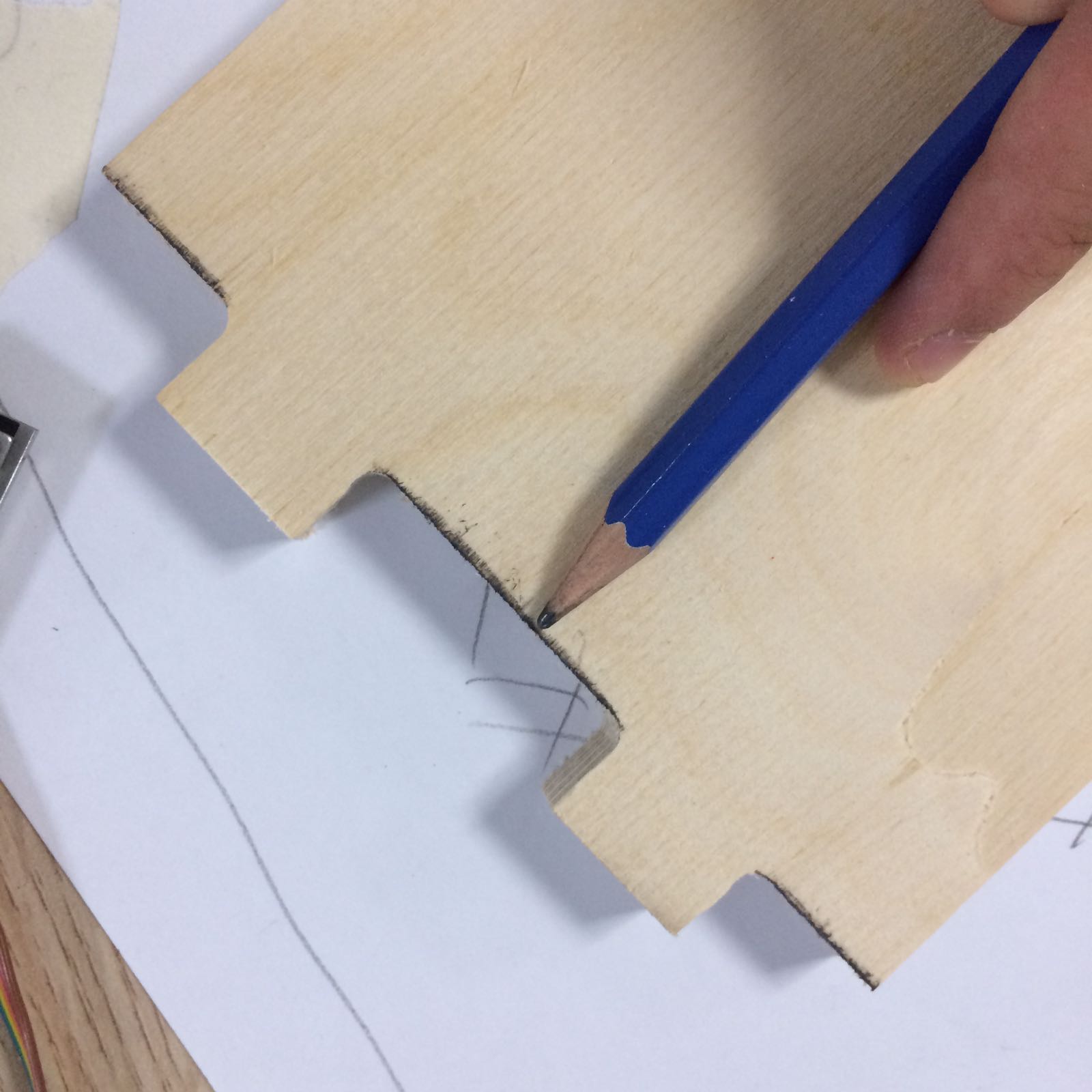
To take the pieces off, we first need to break the tabs, i use a chisel, and then we need to clean the piece a little bit, i used sandpaper, and i was careful not to sand too much on the slots, just enough to clean them. These are some of the tools i used for cleaning. 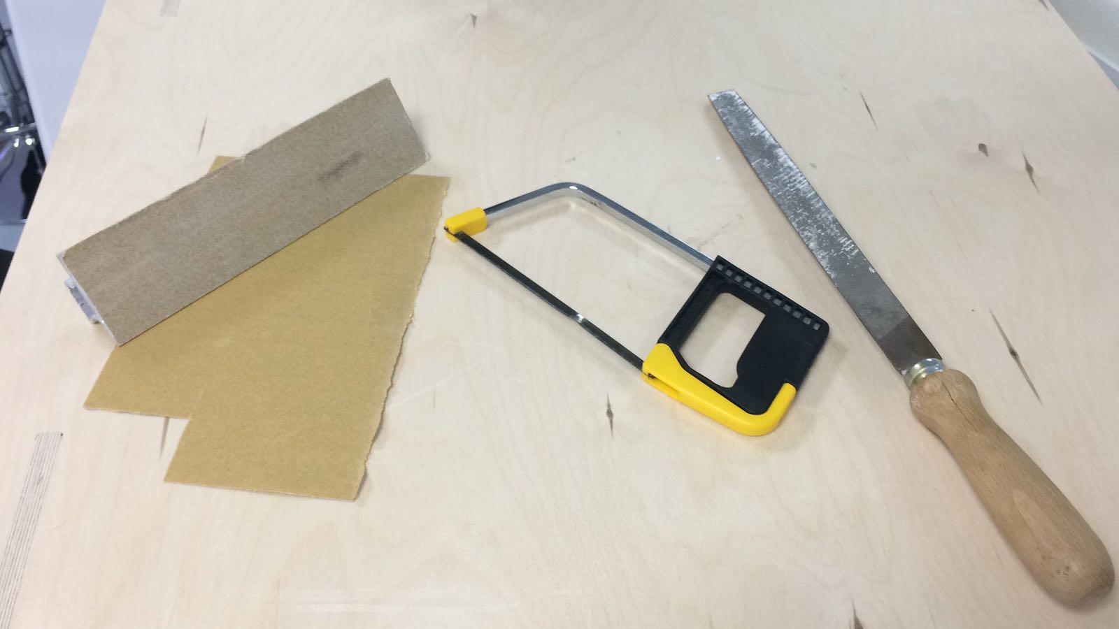
This is the time i found out i forgot to do the dog-bones on the inside slots of few parts, that was okay, i used a rubber hammer to fit them together. i did require some sanding for one part though, it didnt take time, eventually i got everything in. 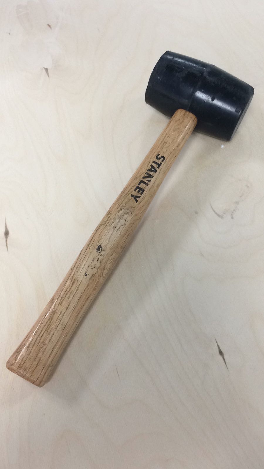
Here is the assembeled pieces. 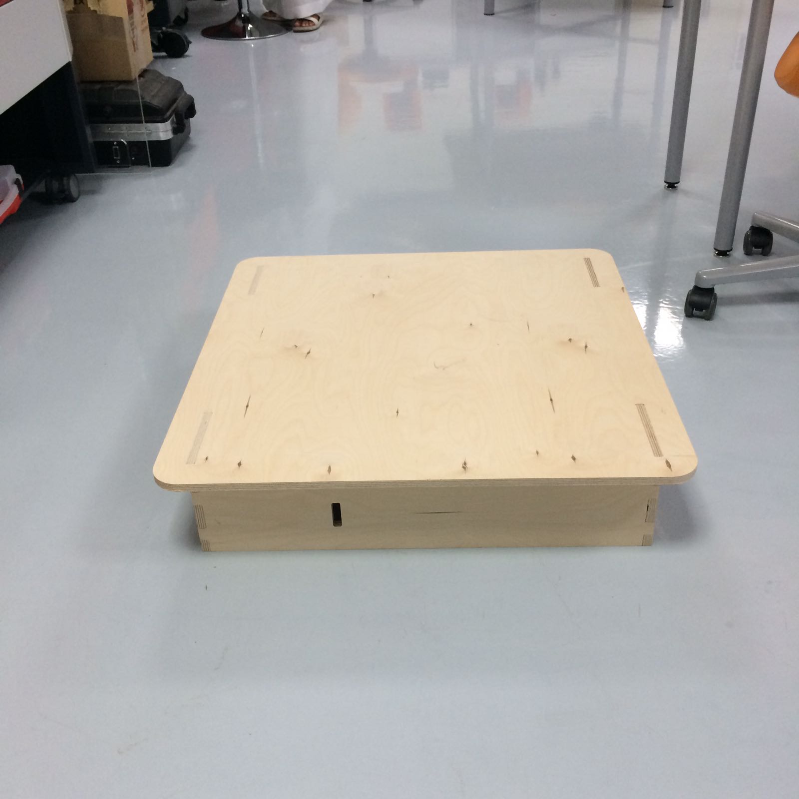
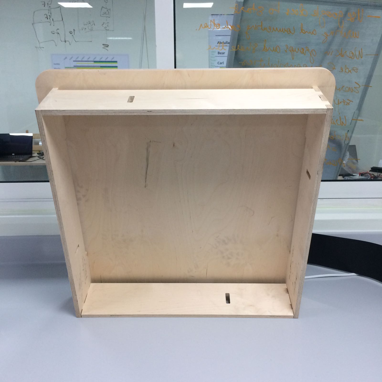
I didn't do the whole thing because this took a lot of my time, i am planning on doing that soon. |