Week09 - Embedded Programming
1-Cables
For this we need FTDI Cable, and the Micro USB Cable, ISP Cable. 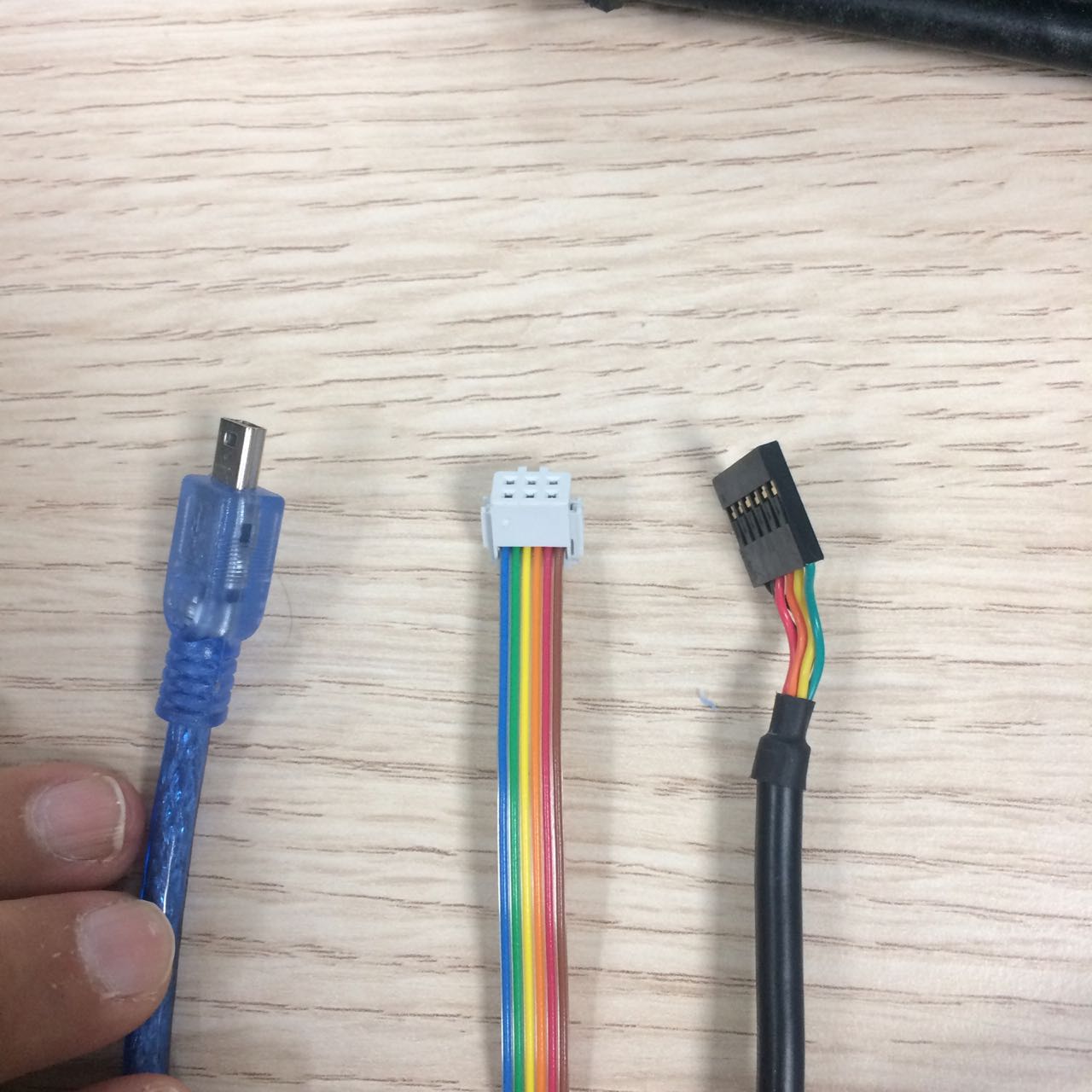
This is how you connect it the wrong way. 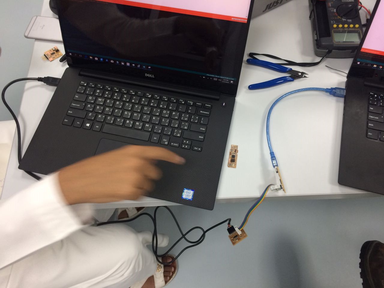
My ISP wasn't working, i thought maybe i would try another usb port, i didn't think it was getting anything else from it except for power. i was wrong, but nothing happened. The correct way is to actually use 2 usb ports from ths same laptop. Attiny LibraryYou can find attiny libraries on the internet, I was already introduced to this library here, by hashim in a session he made for us, then there was this other library that wendy found here, which is more detailed. The way to install the boards library is as follows. 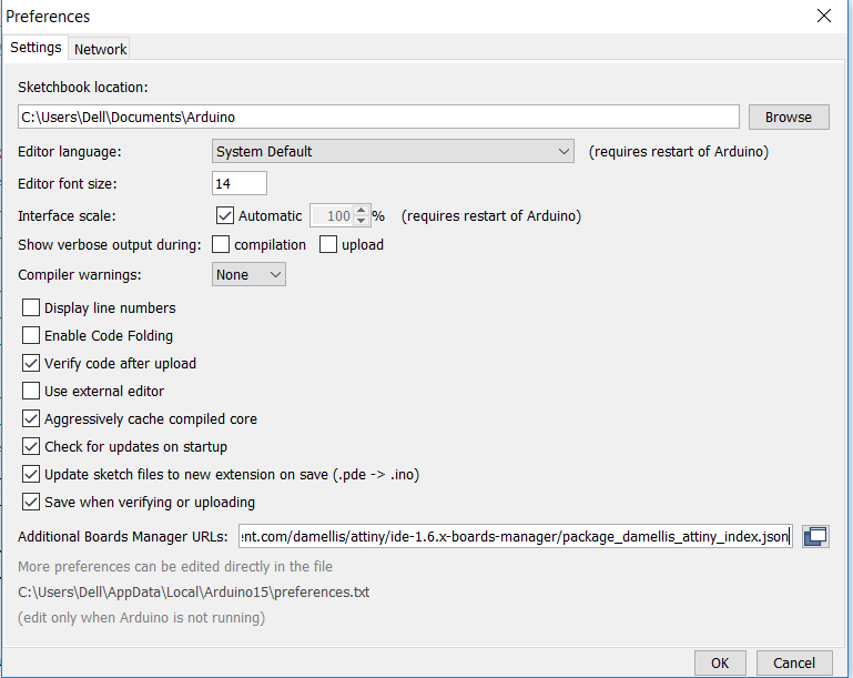
You paste the link into the long textbox "Additional Boards Manager URLs". Then you go to Sketch, boards, board manager and search for attiny, and install this. 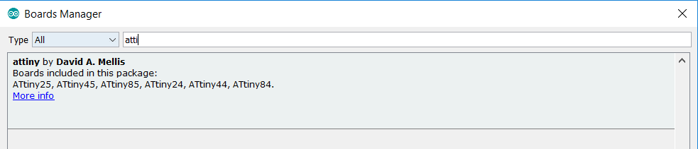
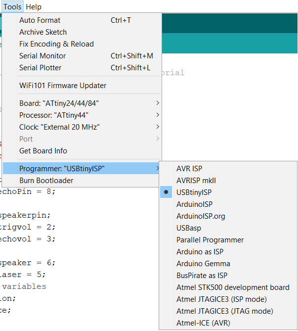
See how many options we have here, although its what we need for programming, there are more options for the second library, see below. 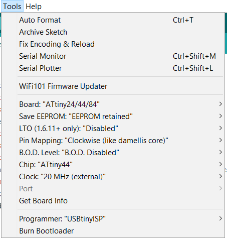
I honestly only used the pin mapping option once, to change clockwise to counterclockwise, this flipped the attiny logic back to normal, for some boards you will find that it has LOW acting as HIGH, flipping the pin mapping will fix that. The attiny datasheet had this figure which helped a lot in understanding it, the datasheet also explained some other things like that all pins have internal pullup. The link to the datasheet here. I have used datasheets in several weeks, week11, week12 for example. 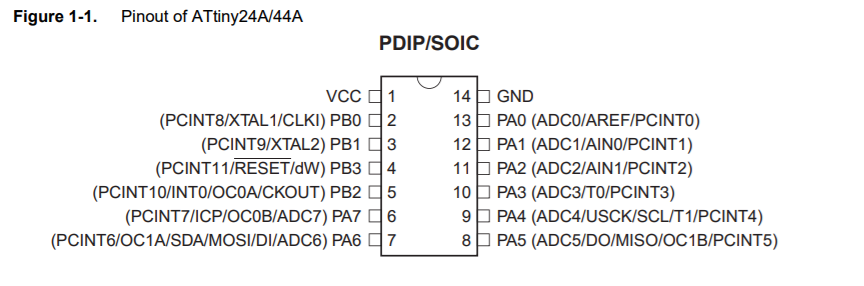
CodingAfter getting the Lib and all the settings correct. Meaning the attiny you choose in the list should match your attiny chip on board, clock speed etc. For coding i used Arduino code, i used the button example and edited it a bit. I worked on the button example, i understood all the parts of the arduino code, and fixed an issue i had with the INPUT_PULLUP, i talked more about that in Week07. 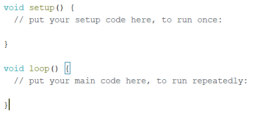
If you want to create a new code in the Arduino IDE, you will get these 2 default functions, setup and loop, this is very similar to what i work with in unity, but instead we have "Start" and "Update" for loop. The setup basically runs once, it is used to assign things values before you begin your conditonal codes, everything has to have a value before you compare it to something else for example. The loop just keep going through everything in it forever, your job is to utilize the loop to do whatever you want. The basic things you will need to understand are, arrays, if statements,switches, for loops and while loops. If you know all of these, you can pretty much do anything. This code just turns the LED on while your button is pressed, the LED turns off when your button is not pressed. I learned that it is really easy to get started programming on the arduino, I learned that arduino is well documented, and most of the things you are trying to do but cant is documented, all you need to do is search and look for the things you need, this is the best way to learn. Download ino file here. First thing we do after the code is that we burn the bootloader for new boards. 
-ProblemsNow i can program!, i just used the examples we already had in the Arduino, Blink + Button. Blink works perfectly! Button however wasn't. I did everything to fix this, checked all my solder, thought maybe some traces are touching, i thought maybe i had some super powers and my body suddenly has the power to discharge electricity! Then Francisco gave me a hint, "Pull up resistor".. now i didn't know what that is, but he and Wendy(Instructor) told me to google it, so i did, and i understood what it did, so i wanted to do it! little did i know that the ATTiny already has a pull up resistor inside, and all i needed to do was activate it using the arduino code, but noooo i was trying to figure out a way to do it physically on the board. Its only once i knew there wasn't anyway to do it unless i trace another circuit that i asked for help, and they told me it's already there! one google search later.. Fixed! I already talked about input_pullup in week07. |