Final Project Concept
Last updated: Tuesday February 20, 2018
 A power conversion device designed to convert rotating power into battery energy. More specifically, I'd like to couple a portable windmill with lithium batteries, theoretically producing a portable battery supply that can provide power for extended durations.
As a millennial I was raised up from the teat of a USB cable so the three things I think are the most interesting future problems are access to power, access to interwebs, and access to computing. This applies (though, unequally,) to developing societies as it does to developed and so I believe that innovation on any of these fronts are meaningful pursuits.
 BY the way, I'll just mention that I'm terribly sorry for the horrific formatting on this page. I started it in Week One, and since Week Four I've been using Strapdown so fixing anything here is just one of those things I have intentions for but will likely never get around to doing.
Yeah so anyway, I know a lot of people go into this course already knowing what their final project should look like, but I'm more the type to throw myself in the deep end and figure out the solution as I build and learn. That's not to say there's no planning involved, but I'm really reserved about drawing a picture of it before the concept has matured.
I'm pretty glad I did this too, since there's a bunch of small things I didn't anticipate I'd learn about and I'm hoping to add them to my project. I started with some simple sketches and block diagrams, and did a few validation tests and I'm pretty comfortable now that what I'm planning to do can be done.
To some this may look like an excessively large project, but I'm here in Dubai full time (self funding this course) and so I have 0 (+-.01) distractions and already have considerable manufacturing experience.
So in saying that, I think the things I experience with won't take long, and the new things I want to learn I will make time for.
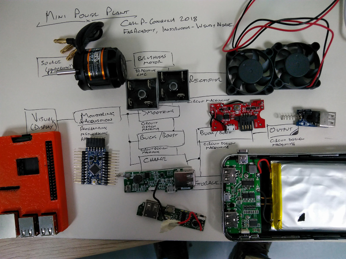
The proverbial "Iron Chef" ingredients I have to use are a bunch of bridge rectifiers I bought in Shenzhen and a brushless motor. How I fold all that together into a neat dish to impress the judges is the challenge.
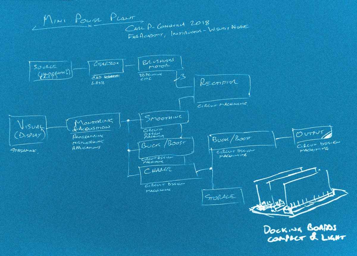
To make a mini power plant there are two distinct areas:
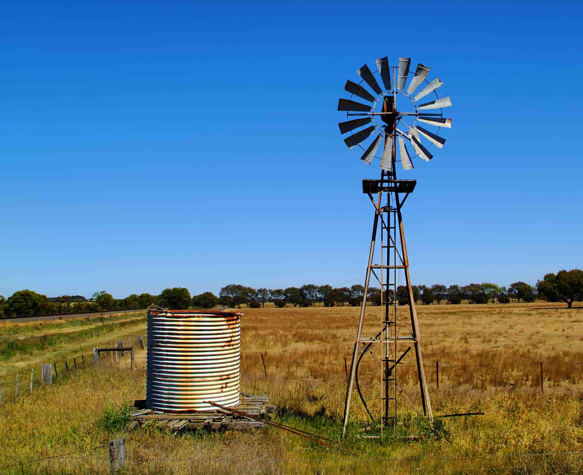
- Mechanical This involves the windmill, gearbox, motor mounting and carry case. As for the windmill, I deliberately won't call it a wind turbine at this point, because I don't think I can really get enough RPM to generate turbine efficiencies but as a way of creating emergency power a windmill style should do. Here's a picture of an Australian style windmill that I'm using as inspiration. I don't think I will actually manufacture the blades due to time constraints (I'd rather focus on designing other aspects of the project.)
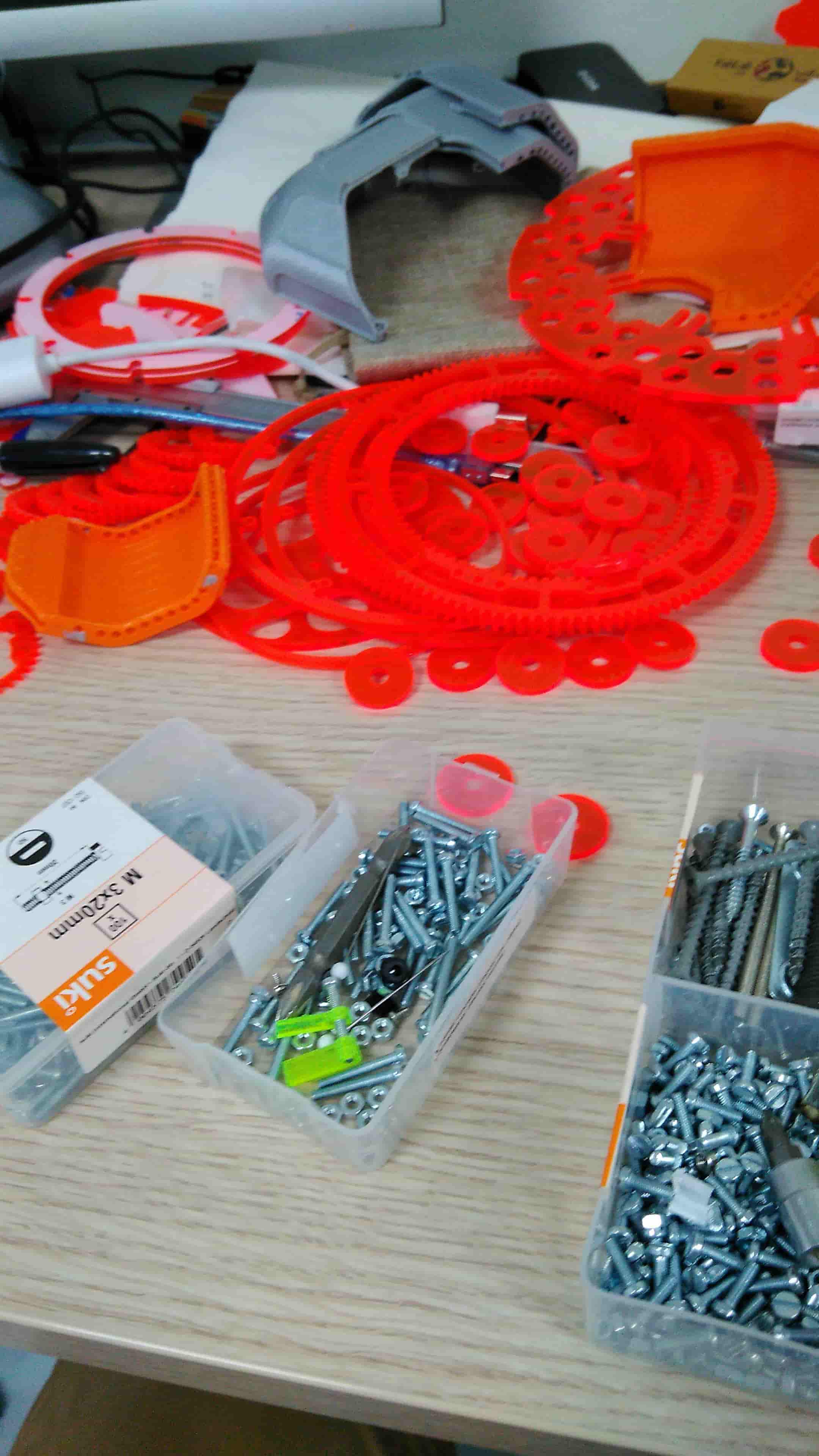
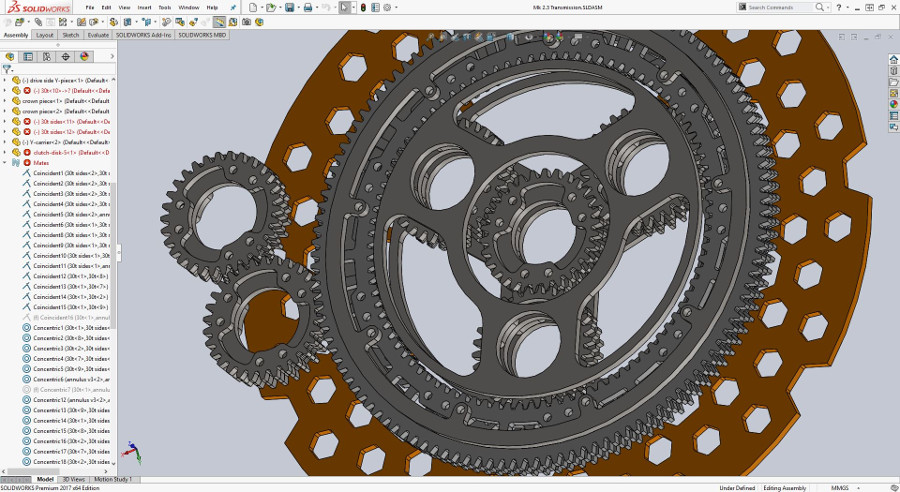
I did some testing on a gearbox over the weekend and it came out pretty good. I will need to order the correct fasteners and bearings but I'm pretty happy with the result so far! Not sure if I mentioned but this was a design I used for a racecar a long time ago that I've modified for use this year, I might get a chance to talk about how it works another day.
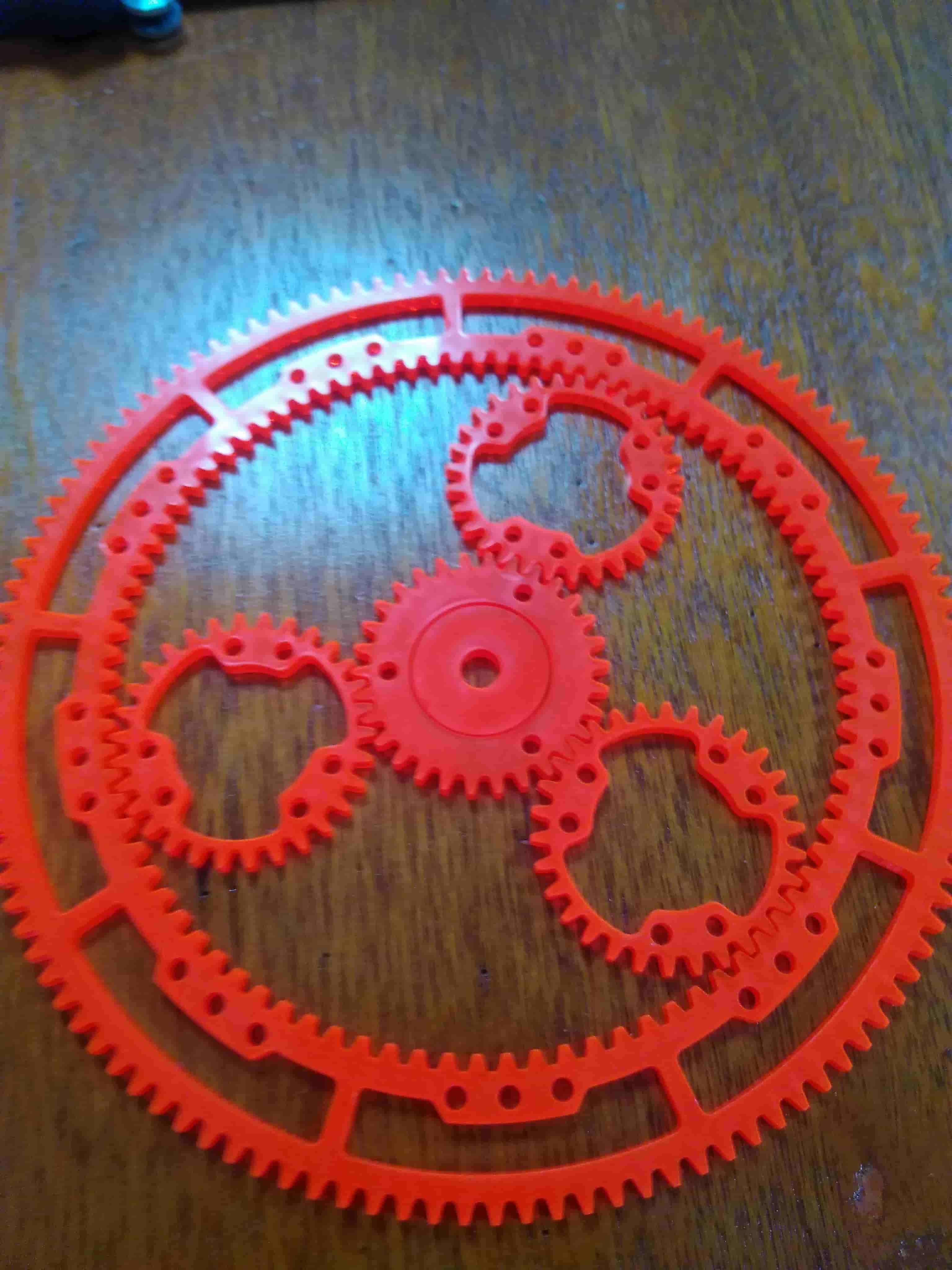
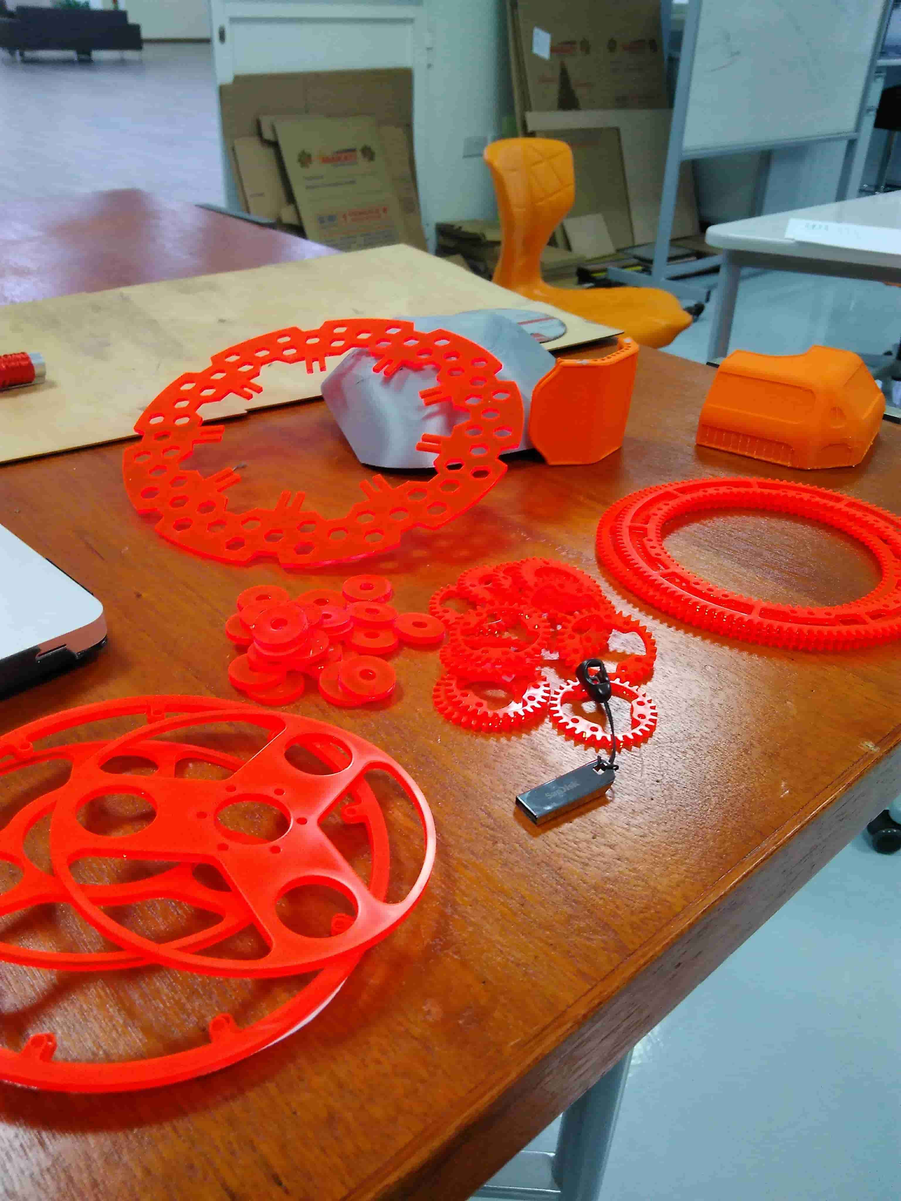
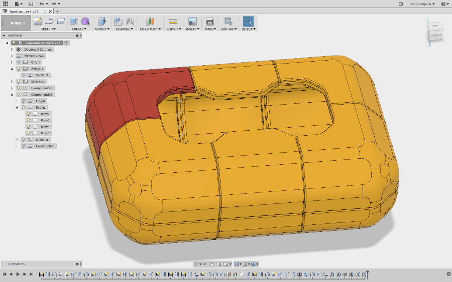
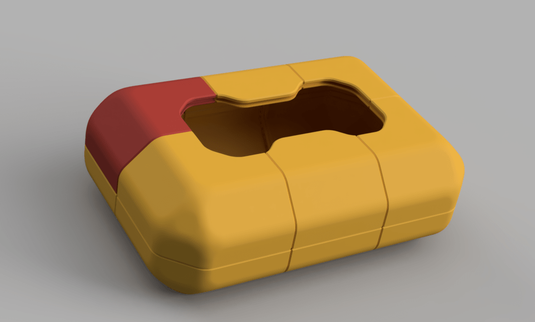
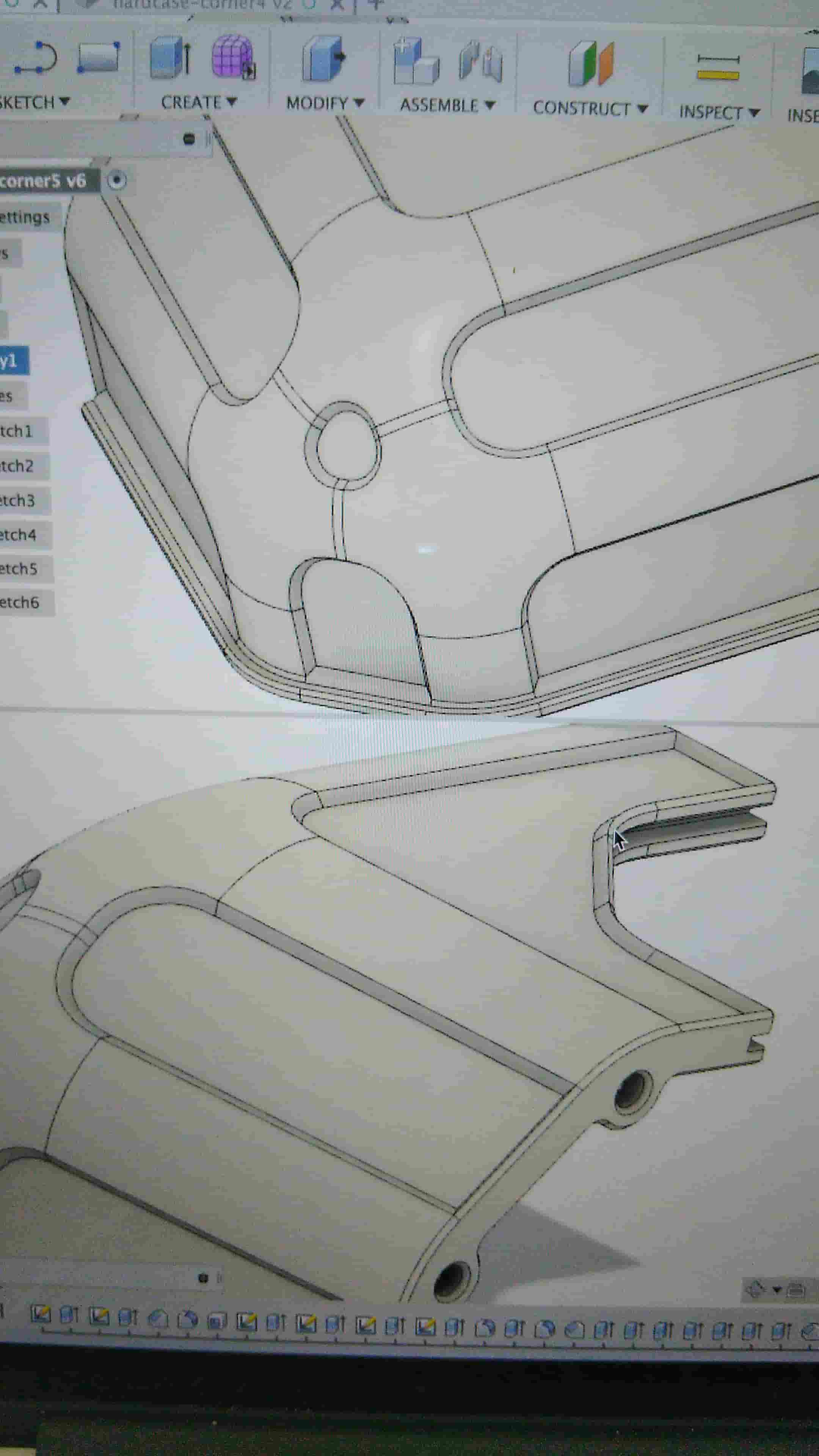
Finally the box - I had been trying to build a case for the project so I am able to take it home! I decided to print it from orange ABS and I'm really loving the texture and the way it prints, it's like smoothing out peanut butter but not the oily type.
I did some impact testing (informal, I banged it against a bench vice) and figured out where it needs strengthening and where weight and print material can be minimised. I got it down to a 155 gram print per section including support which is considerably lower than previous iterations (around double+ that).
Print material wastage is a big worry where I'm from, not so much in this lab but I also don't want others to miss out on the chance to print with peanut butter (orange ABS).
I also designed some hinges and will work on the handle next. Next I'll do a couple test prints of the new design just so I get an idea of stiffness and durability. I suspect I'll need to raise the print temperature slightly too for better layer adhesion.
The electronics parts will involve a power conditioning system and data acquisition. The power conditioning should include machining boards to rectify the waveforms from the brushless motor and then turn them into a useful DC supply for charging batteries. If I get time those batteries will also get to power something like a fan or whatever :)
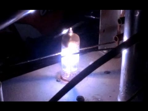
I'm thinking for the rectification stage I can use some LED's in addition to my rectifier bridges to make a V-6 engine layout of LED's to visualise the power rectification step, and somewhat resemble a high powered rectifier made out of vacuum tubes!
For data acquisition I am choosing Raspberry Pi's since I can afford to have one permanently attached to the project as a replacement for a laptop. I'll use it to run a GUI web-server so anyone nearby can log in and see the data in realtime. From the building side I'll have to machine some microcontroller boards for analog-to-digital conversion.
I've never put together a microcontroller before - pretty dependent on Arduino's until now - I'm pretty excited to be able to trim the fat and build a barebones system with only the parts I need.
This project would focus a lot on:
- Circuit board design and manufacture
- 3D printing
- CNC machining
- CAD and CAM
- Laser machining
- Embedded programming
- GUI programming
- Functional programming
Check out where I'm at in class! »»
.
Eat
Sleep
Push
Repeat
Final Project Notes
Last updated: Monday 09 April
## PreambleAfter jumping in on Neil after class I was able to have his opinion and advice on my final project concept. He seemed pleased with the idea (a surprise to me), and mentioned that there were very few wind turbine projects made with appreciable power output.
He also mentioned not to spend time in areas I'm not adding value - for example battery charging circuits and regulation that can be replaced by the use of chips.
He was positive about the use of supercapacitors and a low kv brushless motor as a generator.
Bas mentioned there may be a potential collaboration with someone at Reykjavik who was looking at wind generation to power lights during the winter time where it's night time all the time. I'll try to get out there to visit and say hello!
Francisco reckons he's also coming out to Vestmannaeyjar with the FabLab G-Class. That should be fun!
. ## How to make almost any gear ###(and for kids who want to learn to do other stuff good too!)
Calculations: With a 370kv motor in order to generate at 12V I would need 4440RPM, 5V I would need 1850RPM
From what I can tell low-speed turbines are around 500-1000RPM So that would give me a ratio of around 6:1 with a reasonable band of performance. I have to watch that the torque (and starting torque) for the windmill rotor but given how wide my blades are I’m not *too* worried
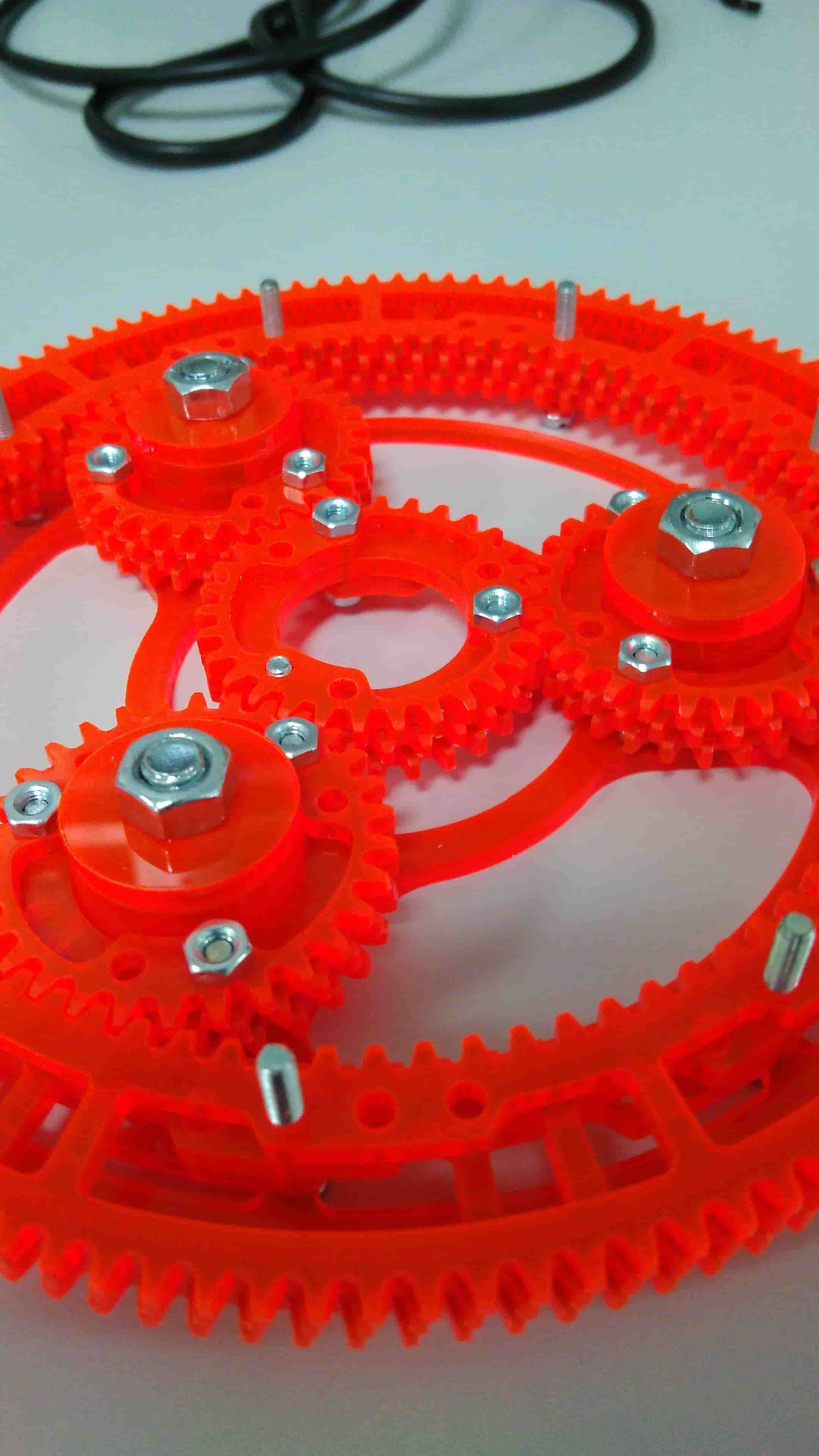
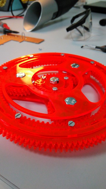
Two ways to do this - one bigass 6x gearbox, Or a two-stage sqrt(6) geartrain. That gives us two equal 2.449:1 gear pairs which would be more compact and lighter
A bit about gears:
Involute shape - Ya know when you’re pulling on toilet paper, if you were to hold the toilet roll still and unwind the end of the toilet paper around the roll, the line that your hand traces is called an involute spline (if you don’t shift your hand up or down the toilet paper).
There’s some crazy mathemagical reason involute splines work but see the animation below and at least you’ll notice why the shape is very specific:

Pitch - number of teeth per diameter. As diameter increases the number of teeth increases by this rate.
Pressure angle - this has to do with how much the teeth push tangentially vs perpendicular to the gear circles. This can be observed by separation force on gears. Typically this is 17deg or 22deg (?) I think
Number of teeth - To prolong gear life-cycle and distribute tooth-wear you want to select a non-integer-divisible number of teeth in a gear pair. For example you would not want to have a 30t and 60t gear train because the same teeth would contact eachother causing repetitive wear and pitting. The easiest way to do this is pick two prime numbers for the gears.
Undercut/Overcut - Is when the tooth tip digs into the root of the opposing gear’s tooth. This can prematurely snap teeth and occurs mainly because of low tolerances in bearings or axle/shaft stiffness. If you know you’re gonna have a wobbly shaft, you can trim the overcut of one or both gears’ teeth, and give them a fillet or chamfer.
Undercut is most prevalent in gears with small diameters (pinions), where the teeth almost look too big for the gear circle and a large undercut at the root of the teeth can cause premature fatigue failure.
Backlash and engagement ratio - Spur gears chatter when they run across eachother. In the animation at the start of this writing it shows a perfectly smooth transition between gear teeth. In reality this isn’t practically achievable because of machining tolerances, tooth wear, shaft stiffness, tooth contact area stiffness and many other factors.
Backlash is when due to these factors, a gear changing direction has some slop before engaging with the tooth on the opposite side. Gearboxes with tight tolerances designed to run in both directions are very expensive.
Engagement ratio has to do with the number of teeth in contact with each other or transferring load. Specifically, it is the ratio between that maximum number of teeth engaged to the number of minimum teeth engaged at any time. Having more teeth in contact helps to distribute the impulse load of any of the teeth that are releasing and the next teeth that are engaging. You can usually increase this by increasing the number of teeth and decreasing the size of them.
In order to properly understand the engagement ratio, consider two gears engage three teeth at the best of times, and in the momentary transition when there are only two teeth in contact while transitioning. This gives us an engagement ratio of 66%, which would mean a lot of chatter and a lot of impulse load on the shaft (both bending and torsionally). If we decreased the size of the teeth to achieve a maximum engagement of 5 and minimum of 4, that would raise our engagement ratio to 80% which would show us markedly reduced chatter and impulse.
One other way to reduce backlash and engagement ratio is to use a helical tooth profile. Helical teeth allow for continuous transition of one tooth engagement to another, as well as having more tooth profiles in contact at any one time.
#Step One: Get your profiles from Gear Generator, this guy did an awesome job and make sure to check out his other projects for making cool plots and graphs
Mount your gear or shaft centres exactly (Diametral Pitch)x(Num of Teeth)/2 away from each other. This is also the same as (Radial Pitch)x(Num of Teeth). If your pitch is in inches, then this number is inches. If you're part of the smar side of the world, this number is in mm.

