This week assignment is to do a board with an input device.
My goal for this week is to finish the board with IR and then add servo motor.
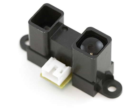
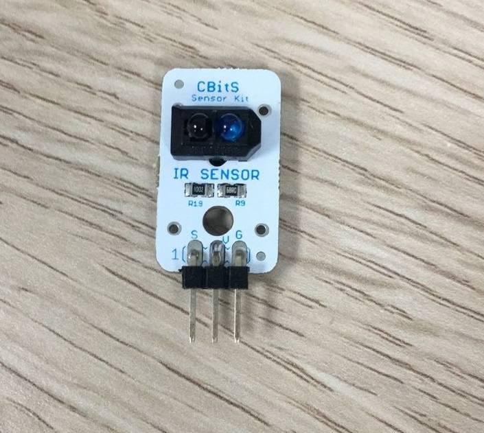
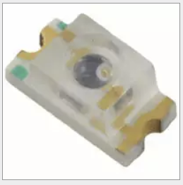
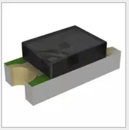
I didn’t do anything in input week because I was busy with other thing related to the college. I searched for sensors will benefit me on my final project. I found three IR sensors first one is Infrared Proximity Sensor Long Range, The second is IR sender and receiver, The third one is IR LED as a sender and Phototransistor as a receiver.
I searched for this sensor and I found out from here the measurement distance of this sensor is from 20cm to 150 cm so it will not help me because it's too long for me.
I thought of using this sensor because its ready-made. But also detection range was not good for my use because it's less than what I want.
I chose these two because they are not like the other sensors. I must locate the sender and the receiver also it gives the choice to change the receiver from Phototransistor to photodiode. Also, I will use this sensor to know the distance it detects because I don't know what is the range for this sensor.
After choosing the sensor I opened week 7 board because I don’t want to make a new schematic from zero.
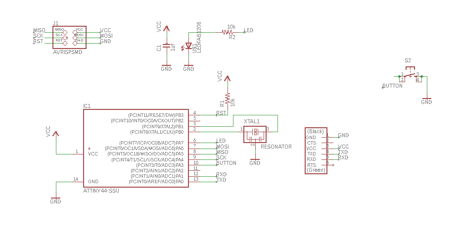
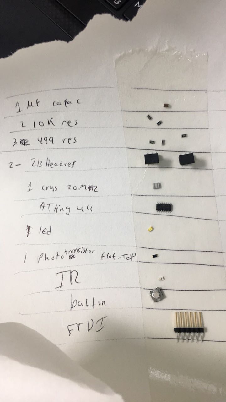
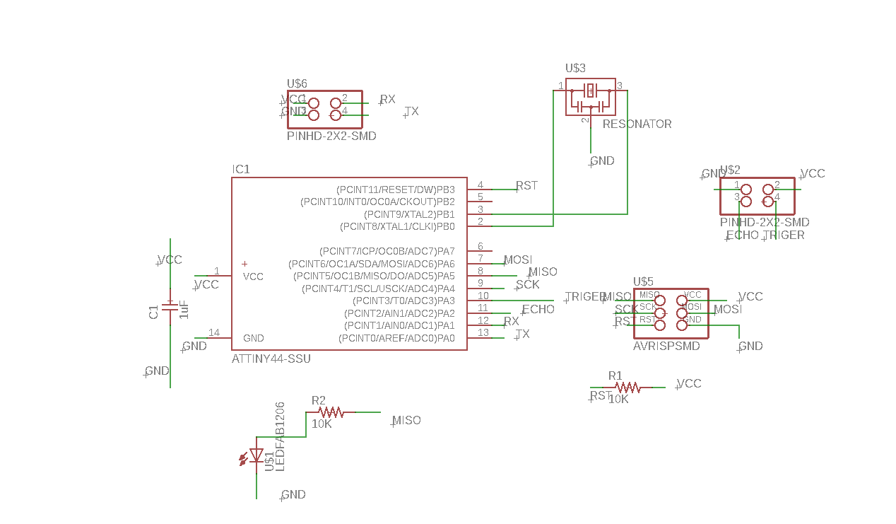
Then I added IR LED as a sender and Phototransistor as a receiver, 3x2 Header, two 499 ohm resistors.
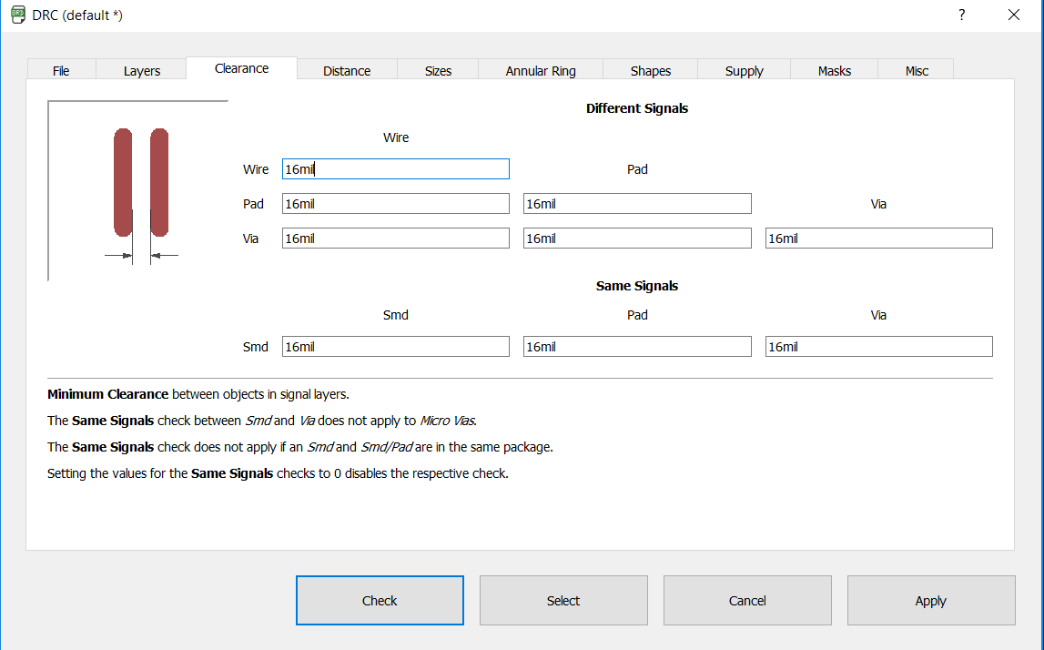
When I finished the schematic I couldn’t generate it to a board and this error message appears.
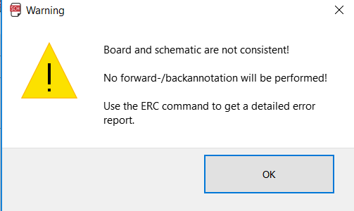
I tried and search then it turned that I changed something on the board and I didn't change it in the schematic. so I followed this solution I copied the component and opened a new schematic and past it there and added the new component.
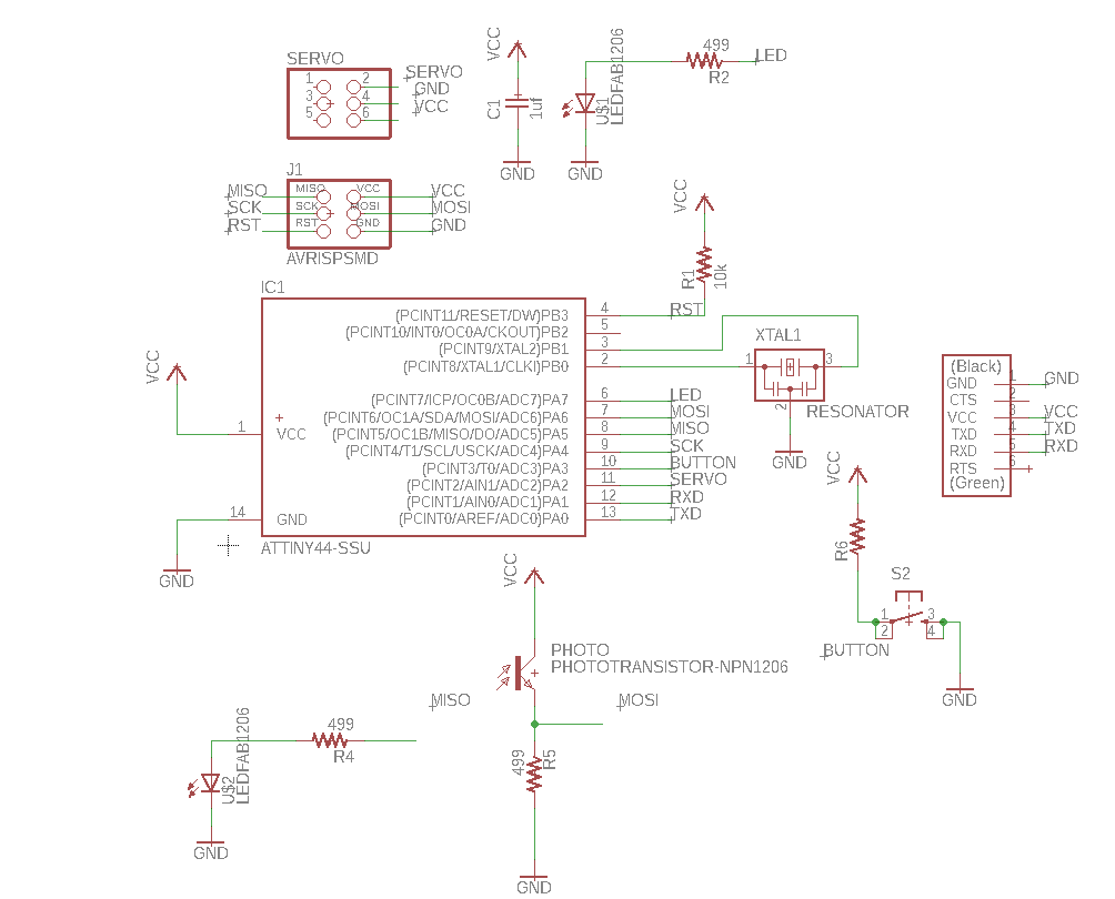
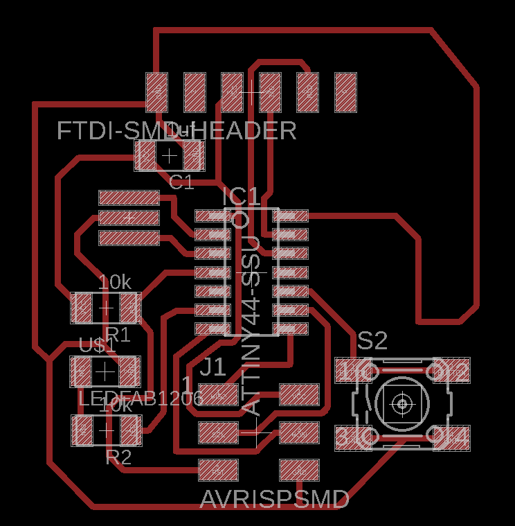
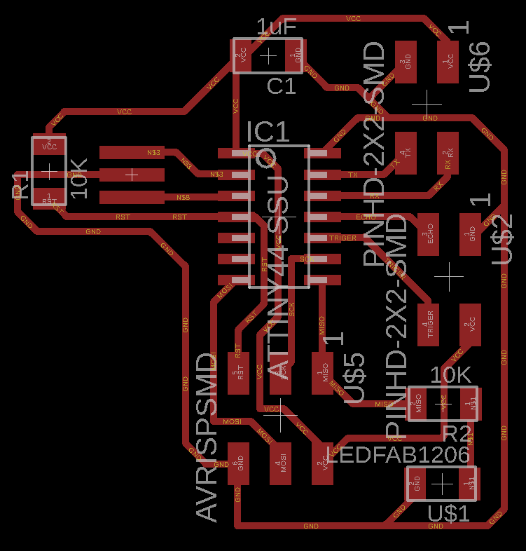
Then I changed the wire width from 6 to 16 and little on the design and I put the IR and the Phototransistor near to each other. I made a distance between them to but a border. The border function is to prevent the Phototransistor from the side light when the IR is turned ON.
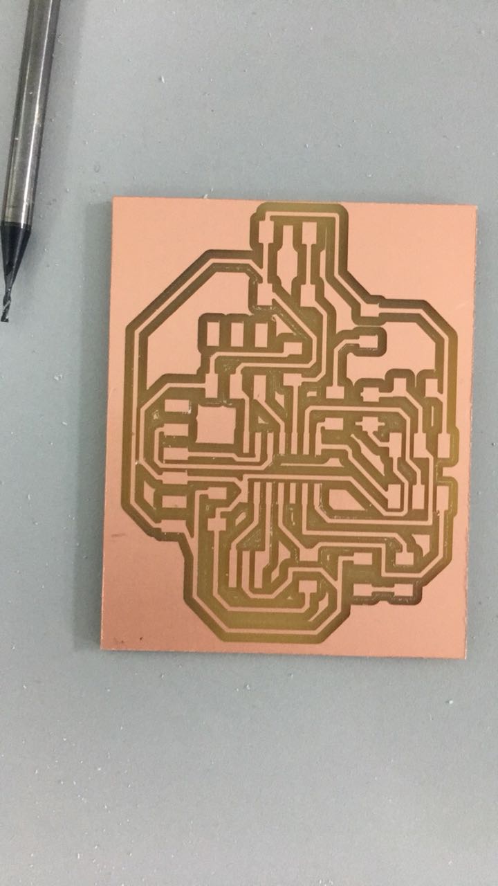
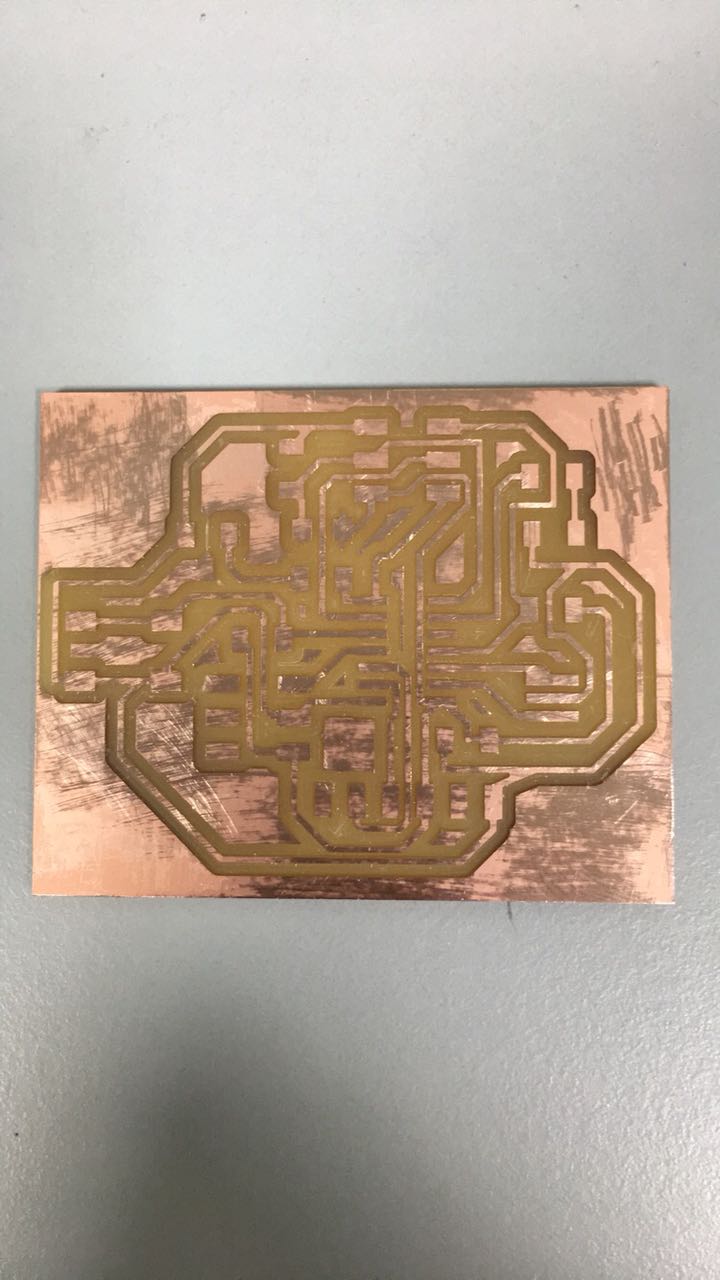
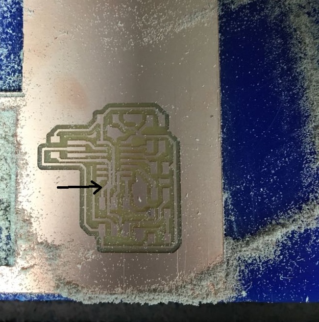
In milling, I did it two times. The first time I forget to add the second 3x2 header of the servo motor. So I adjust the design and print it again. Then I thought of testing the connection of the board by using multimeter before butting the component. I notice in some parts there was no connection. So I used a roller to rub off the upper part of the PCB. When I did this there was a white material that was preventing the current.
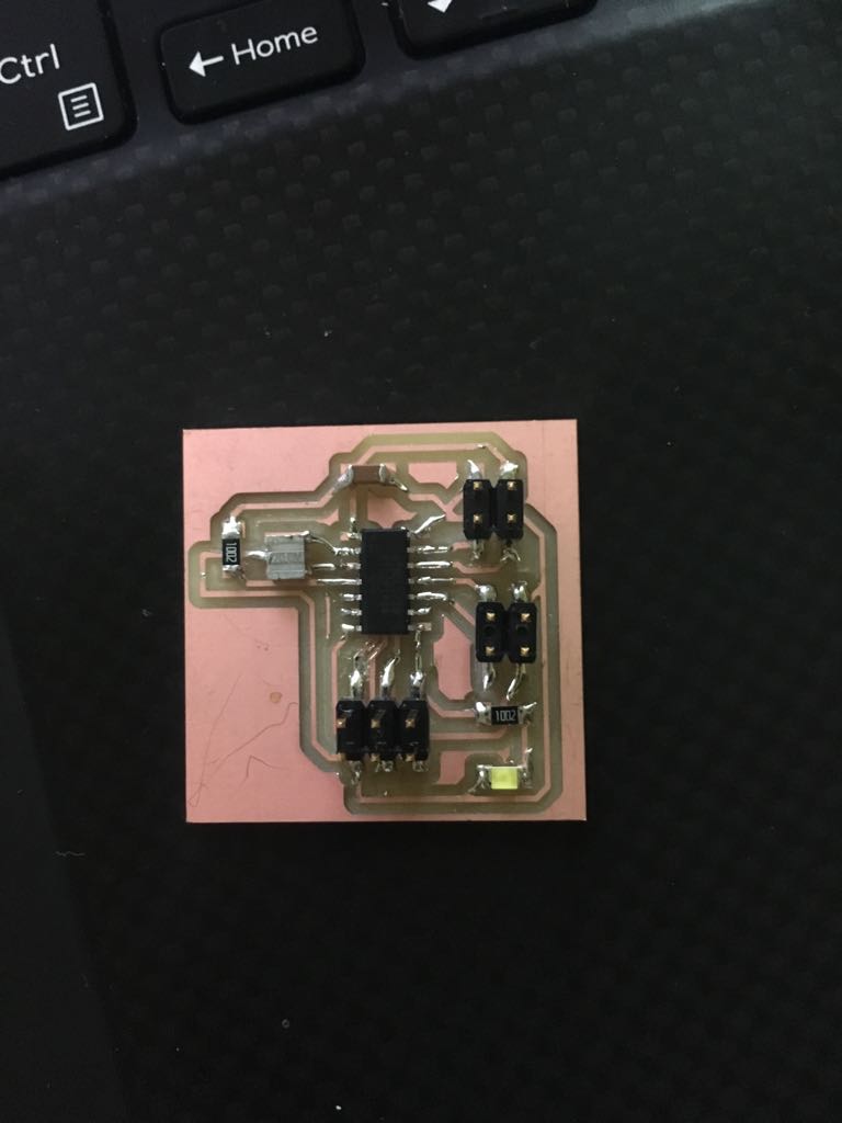
Then I solder the component and it didn't take a lot of time from me
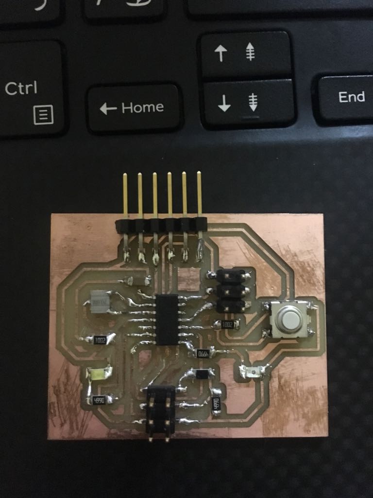
When I wanted to program the board it didn’t work. I discovered that the normal LED is flipped like the previous time even though I know the cathode must connect to GND. After that, it didn’t work and in Arduino, it told me there is a problem with connection. I went to Hashem to discuss with him the problem when he saw that the microcontroller also flipped so I took off the microcontroller and replace the new one in the correct way.
The first code I did was to blink the two LED to know if the board and the two LED works.
        void setup() {

  pinMode(7, OUTPUT);
  pinMode(5, OUTPUT);
}

void loop() {
  digitalWrite(7, HIGH);
   delay(1000);
     digitalWrite(7, LOW);
   delay(1000);
   digitalWrite(5, HIGH);
  delay(1000);

   digitalWrite(5, LOW);
  delay(1000);
}
Here is the schematic
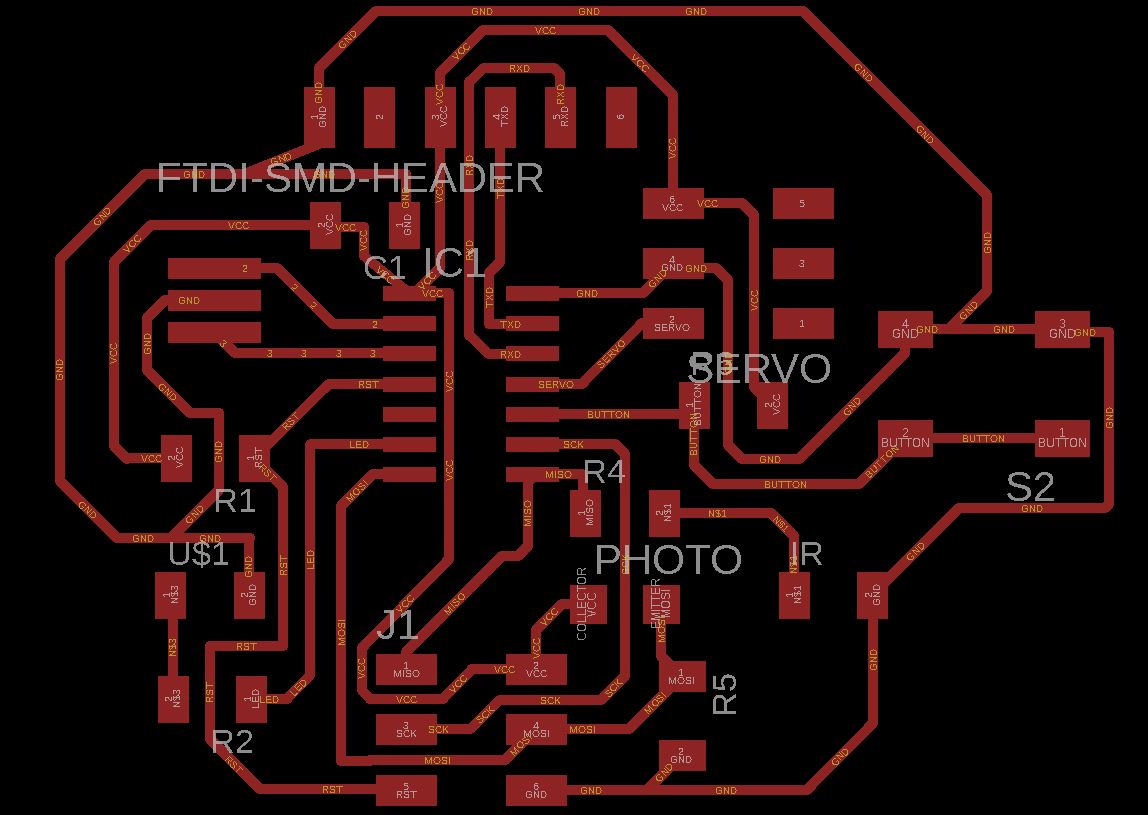
Here is the board
Here is the traces as png
Here is the outline
Here is the test code
Then I start programming to test the sensor but I coulden't. The sensor didn't work I think the reason is the location because I put it in a way when I connect the rainbow connector it cover the phototransistor. I know there is a solution but at that moment I really wanted to change the sensor to ultrasonic.
I first checked how ultrasonic work. So I searched on how to connect it to Arduino and I found this page. I learned from the page how this sensor work also how to calculate the distance.
Ultrasonic send ultrasound at 40000HZ and when an obstacle is in the way of these waves, it will hit it and return back to the sensor which by some equation can tell you the distance of that obstacle. I also learned that ultrasonic set the trig to send ultrasound for 10µs then the echo will receive it. This image below explains more(I took it from the same site).
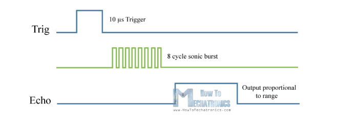
To measure the distance I must know the speed of sound which is 340m/s I must change the unit to cm/µs so the speed will be 0.034cm/µs because Echo sends the time in µs. Then I learned an equation to get the distance which is (s=(t.v)/2). The simple of distance is (s) and for speed or velocity is (v) and (t) is time. The speed is constant but the time is variable which we get from Echo. The reason for dividing them by 2 because the time we will get is the time for going to the obstacle and returning back. Because we want the time of going so we will divide by 2.
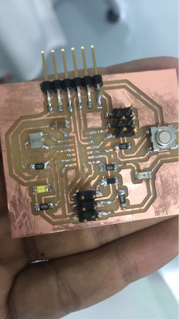
I made the new PCB which is the same as week 7 PCB but I removed the button and I replace the ftdi with 2x2 header which have (GND,VCC,TX,RX) also I added another 2x2 header for the ultrasonic GND,VCC,Trig,Echo.
After designing the PCB I followed the same process in week7 and week5 in milling, soldering, visual inspection and testing, the PCB and finally I did it. In testing I noticed two traces connected so I separated them.
I took the code from this page and I modify it to work with my PCB. I clicked on burn bootloader and I uploaded the code and it works. After that, I change the code to add LED to make it flashes if the distance is more than 15cm and turn ON if its less than 15cm.
Here is the schematic
Here is the board
Here is the trace as png
Here is the outline
Here is the code
This week took a lot of time because I didn't have free time already I'm late so I tried the IR but it didn't work with me and I really didn't like to continue with it so thank God I changed my mind. Regarding the problems I faced with the LED and the microcontroller, I learned a lesson to check the orientation also to double check even if I'm sure I did it correctly. The ultrasonic sensor I think will be the best sensor for my project and already I made the first design of the project which has a place for this sensor. I learned from this assignment a lot and I hope this sensor to work well in my project.
.png)
.png)
.png)
.png)