This week we must make two PCB talk to each other.
My goal for this week to press a button from one board that will tern ON the LED in the other board.
To do this task I went to read what the previous student do. I saw UAE student profiles they did the same as what I want but the big difference was they used C+ in programming and they make a new board for the task(Neil board). I decided that time to go like what they did so I started to search hoping I could find one who use Arduino to make the networking. Finally, I found student called Arpi Maheshwari who used Arduino in here networking week.
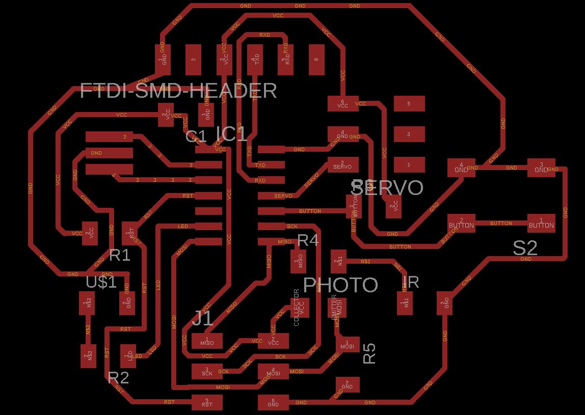
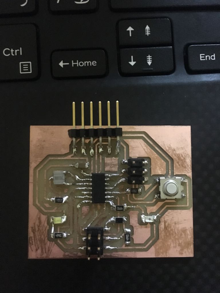
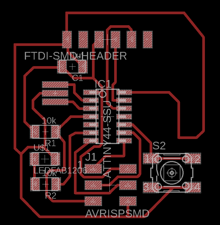
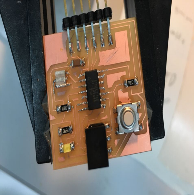
I used two boards in this week one is the last board that I made Input and Output week. As a sender, this board will send the command to turn ON the LED when I press the button.
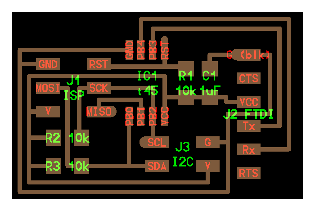
The other board is one I made in Electronics Design. This board will be the receiver will receive the command from the sender to turn ON the LED.
I went through Arpi Maheshwari page then I downloaded here codes. She made networking between three boards the sender is here distance sensor board and the followers OR the receivers are RGB LED and Hello echo "LED" boards. So I deleted the RGB code because I don't want it I just want the code of one sender and receiver to understand how it works.
I spent a lot of time testing the code. The first thing I notice in the code was (serial.write) it's the first time for me to see it. I looked in Arduino page about serial.write to understand it. Since there is serial.write, of course, there will be an order to read so I went again on Arduino Website to read about serial.read. After that, I understand the code she made of the sender and the receiver then I made my own code.
After I finished with the my code I wanted to download it. I realise there is two codes and two boards so the logic says to download the sender code in the sender board as I download any normal programme using the programmer then disconnect the rainbow wire and connected to the receiver board to download the receiver code.
The sender
The reciver
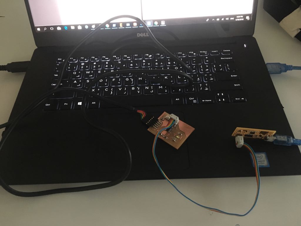
After I download the two codes on both boards. I make the connection like this I thought it will work.
Then I realize there is no power for the two boards :).
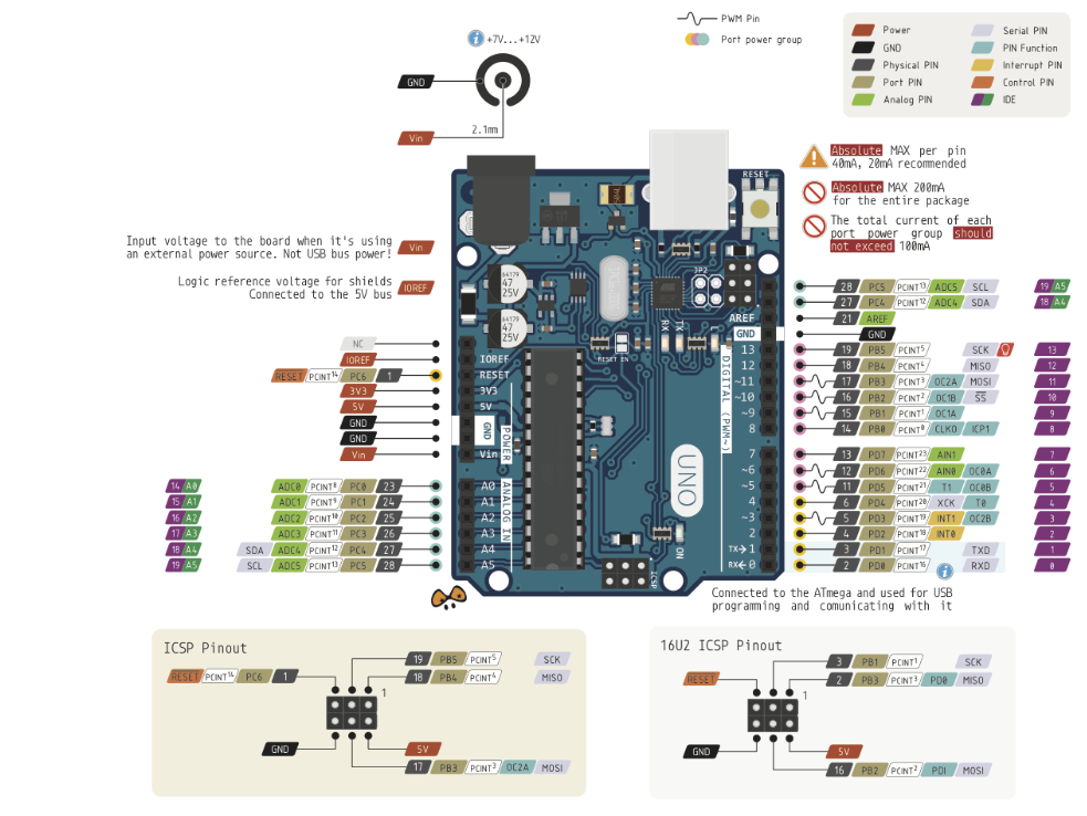
because I added in the sender board if I press the button to send data also turn your LED ON( just to test if the button work) but when I press the bottom didn't turn ON. So I used Arduino just to work as a power source. I didn't know where is the GND and VCC in the Arduino header so I looked on the internet and I found this image from here.
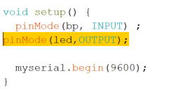
Then the sender board worked because I connect rainbow wire from Arduino header to the header of the sender board but there was little problem. I notice that the LED light was not bright but it was ON. So I opened Blink program from exampled and discovered that I didn't write (pinMode(led, OUTPUT)) in the setup void. So I fix it and it works :).
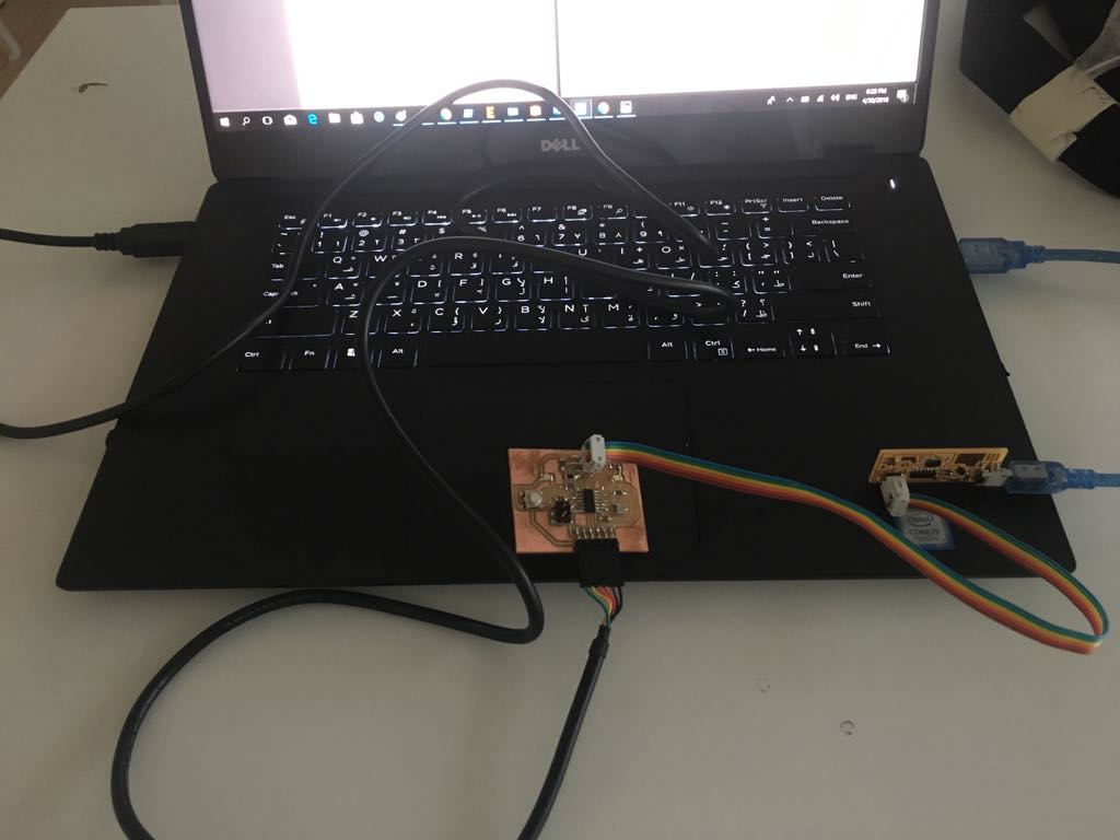
After that, I connect the VCC, GND, and Tx of the sender board to the VCC, GND, and RX of the receiver board. I notice something else when I press the button the LED in the receiver didn't turn ON so I changed the TX and RX until I connect RX to RX it works.
Then I change SoftwareSerial myserial from (0,1) to (1,0) and it works. I connected VCC, GND, and TX from the sender to VCC, GND, and RX in the receiver and it works.
Finally, I will put the sender code as you can see below, its a simple code this code is for a bottun. I used myserial.write to send the character 1.
The sender code
The receiver code is simpler than the sender like I said it will receive the command and turn the LED ON.
The receiver code
To download the original code you can visit her page here.
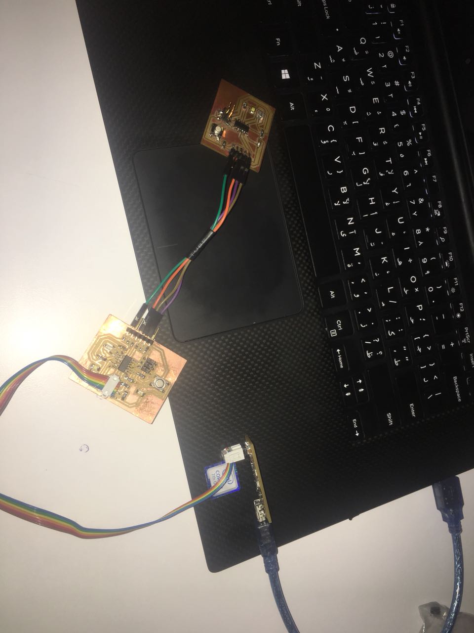
After that, I repeated the experience but using three boards. One master which is a ttiny44 and two boards as slaves one is Atmega328 from output week and the other is attiny44 from input week. I made attiny44-slave to turn ON the LED when it receives 0 from the attiny44-master and to confirm it get the order by sending(attinyreceive). Atmega328-slave will turn ON LED when it receives 1 from attiny44-master and will confirm it get the order by sending(atmegareceive). In the video, I pressed the button of the master and it turns on the led of atemag 328. I increase the delay just to see the process and how they talk.
Thanks to Zubair for his awesome video recording.
attiny44-master code
attiny44-slave code
atmega328-slave code
I learned a lot this week and I troubleshoot a lot also. I'm very happy with what I did till now I finish this week quickly I didn't delay it more. I notice a big improvement with Arduino I gain every time more knowledge about it I can now write a code for LED to blink and to add serial without looking at examples. Regarding this week assignment at the beginning, I thought it will be hard and since the old fab UAE student they used C language I thought this will be hard, but when I found Arpi Maheshwari I felt more confident on continuing working I would really like to say thanks for her.