In this week we have to read a microcontroller data sheet program my board to do something, with as many different programming languages and programming environments as possible.
To bear reading the datasheet and to program my week7 board by using a code that contain the button and the LED.
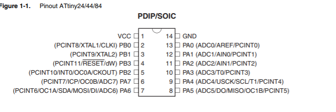
The first thing I did was to read the datasheet. I know I will not understand a lot, but I took the challenge to try to read it for 40 minutes. I didn't get a lot of knowledge but yeah I learned some stuff. I learned that there's 14 pins on attiny44 there is VCC and GND and above the vcc pin there is a dot to indicate the location of pin 1. Also there is 8 bit I/O(Input/Output) called Port A (PA0 - PA7) and there are 4bit I/O called Port B(PB0 - PB3). In Port B there is a pin used as a reset which is PB3. All of the ports have internal pull-up resistors. In week 5 and 7 we defined PA0 as TX(Transmitter) and PA1 as RX(Receiver) -its not written in the datasheet - but I make this as a standard for me. If I connected an LED on PA4 I will write on arduino (int LED=4).
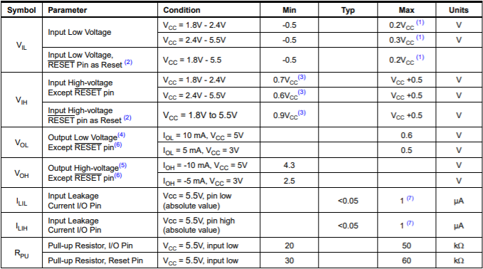
Also, I learned the operation voltage for it by looking at this schedule.
In this week we must program the board that we design in week 7.
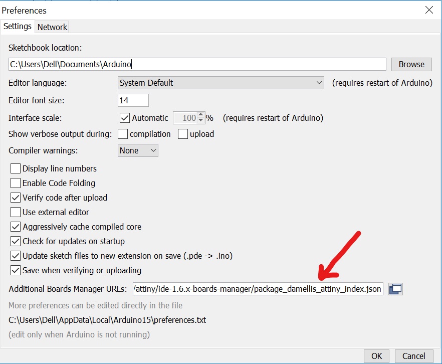
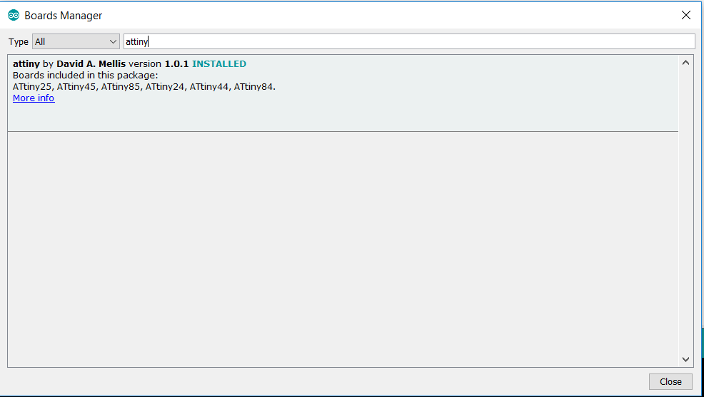
Hashim gave us a session on how to add the library of Attiny44 also how to program it in arduino. So in order to use Attiny44 in Arduino you must add the library by copying this URL https://raw.githubusercontent.com/damellis/attiny/ide-1.6.x-boards-manager/package_damellis_attiny_index.json to preferences then the URL bar.
Then I clicked on tools->board-->boards manager. Then I wrote Attiny44. After I found it I clicked on (more info) to install it.
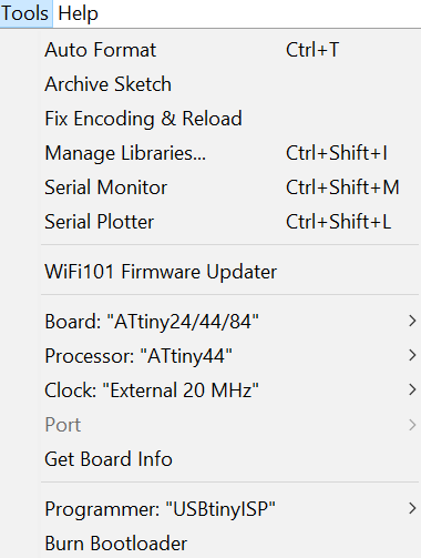
After that I went to tools to change the board - I selected the attiny 24/44/84, then in the processor I chose the attiny44, in the clock I choose the External 20Mz (you can see it in the picture above) and the programmer I change it from ArduinoISp to USBtinyISP which is the programmer that we made in week five.
To be honest, I didnt burn bootloader but when I connected to zhara laptop it works even though I used my own programmer. I dont know why but yeah maybe because of the problem that I discover later which is I changed the drivers of my old board (the programmer). I learned from my evaluatotr steven this info "Burning the bootloader programs the fuses on the ATtiny chip. Depending on how the fuses need to be configured for your program, if you don’t burn the bootloader, your code may not work".
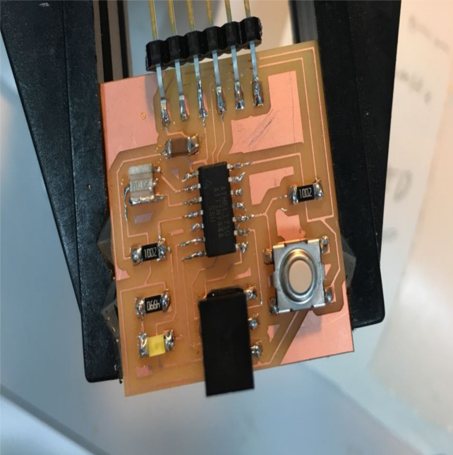
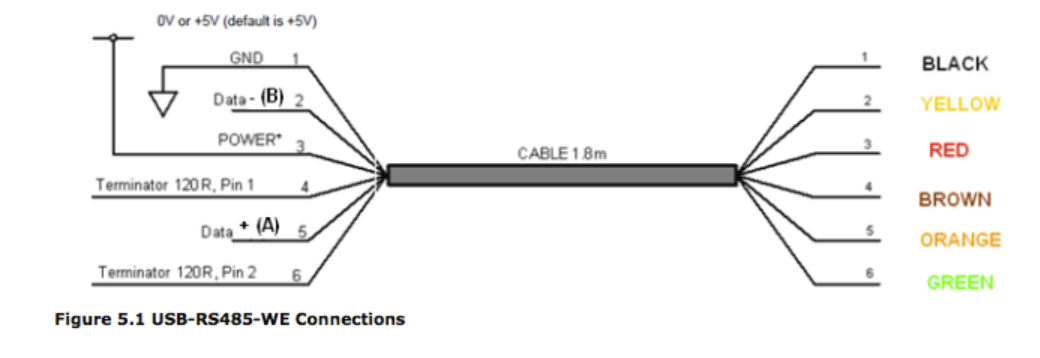
In order to program the new board I must use FTDI cable and to connected with the board. I used this image to help me know where is GND.
After that I connect the programer to the new board using Ribbon cable Then I started with the code. Before I started with the program I thought of using simple code to see the board working. I thought of using blink code. I open the example from arduino but I couldent compile it. It show this error masege which shown to me before.
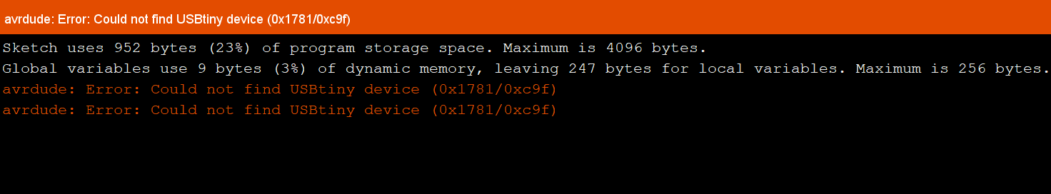
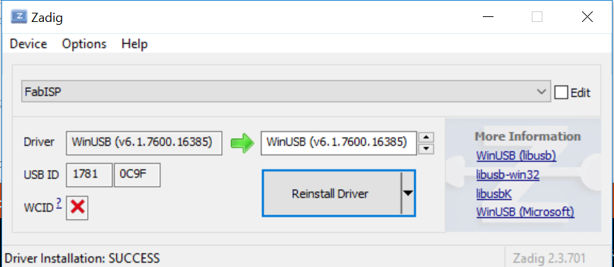
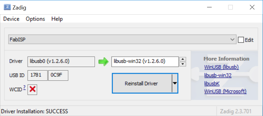
I tried to solve it because I dont want to use others labtops evertime. After alot of searching I remembred that I change the drivers of the programer from libusb-win32 to WinUSB. So I changed it back to libUSB-win32 and it works:).
After that I used my scematic and this image to locate the pins of my button and LED.
I know little about Arduino because I'm now working on my college graduation project which requires using Arduino. So I learned how to make a code for LED, IR, button, and Servo. I made the code for this PCB it wasn't complicated. I compiled the code and it didn't work so then I discovered that the LED in the Pcb is flipped. So I took it out and solder another one in the right way. The right way is to connect the cathode to GND to know the cathode you will see a dot in the component this datasheet will help you .
The code was turning the LED ON when I press the button. when I take out my finger from the button the LED keep flshing.
This code I made. Its similer to the one in Arduino examples(blink)/* * The code is for turning the LED ON when THe button pressed and blinking when its not. * This code originally made by Eidha Alrashdi for fablab 2018 * 17/3/2018 */ const int buttonPin = 3;// The button is connect in pin 3 which is PA3 const int ledPin = 7;// The button is connect in pin 7 which is PA7 void setup()// here we define { pinMode(3, INPUT);// Here I idintfy that button is input. pinMode(7, OUTPUT);// Here I idintfy that LED is output. } void loop()// here the code will be repeated { buttonState = digitalRead(3); if (buttonState == LOW) // If the button is pressed LED will turned ON. { digitalWrite(7, HIGH);// high means 1 or ON } else// if it is not pressed the LED will flash { //Flash: digitalWrite(7, HIGH); delay(100); // digitalWrite(7, LOW); delay(100); digitalWrite(7, HIGH); delay(100); digitalWrite(7, LOW); delay(100); } }
I wrote this page thw second time. The first time I wrote it was missing one image. when I wanted to add the image I was shockd I couldent open The html so I do it gain. Regarding the week I didnt know tha making a code to the board easy I thought of complicated things. I like the fact of learning things here that I thought it will be had for me. Thank God I found out the sulotion of the proplem that I face.