Menu
HomePrinciples and Practices
Project Management
Computer-aided Design
Computer-controlled Cutting
Electronics Production
3D Scanning and Printing
Electronics Design
Computer-controlled Machining
Embedded Programming
Molding and Casting
Input Devices
Output Devices
Interface and Application Programming
Networking and Communications
Mechanical Design
Machine Design
Wildcard
Applications and Implications
Invention, Intellectual Property, and Income
Project Development
Final Project
Week 11
Input Devices
Week Assessment :
Add a sensor to a microcontroller board that you have designed and read it.
I think it will be a great idea if I begin to do something related to my final project and that why I chose to use gas detector sensor. I started to download the library that I need for designing a board.
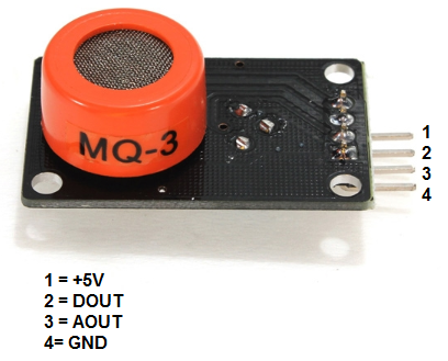
Firstly, I looked thru the sensor Datasheet. From the pinout of MQ3, there are V5 which is the VCC and GND which is ground, for the data for the data there are two pins which is Dout refers to the digital output signal and Aout which refers to the analog signal. So what is the difference between analog and digital signal? I found this good explanation in Wikipedia. I took the summary of it.
Analog is a continuous signal for which the time varying feature (variable) of the signal is a representation of some other time varying quantity. There are different types of sensors that produce a continuous analog output signal and these sensors are considered as analog sensors. This continuous output signal produced by the analog sensors is proportional to the measurand.
Digital is a binary signal, also known as a logic signal, is a digital signal with two distinguishable levels. A digital signal is a signal that is being used to represent data as a sequence of discrete values at any given time it can only take on one of a finite number of values. This contrasts with an analog signal, which represents continuous values at any given time it represents a real number within a continuous range of values. Data conversion and data transmission take place digitally are called as digital sensors.
Then I search if someone did something similar to my project, and I found this awesome page
MQ3 is not CO2 or smoke sensor but it's a good way to start with and many people have been used it. I did some search and I found that are the differences between MQ modules because I saw some people used MQ2, and I found the answer on this webpage awesome page . The difference between MQ2 and MQ3 is that MQ2 detected smoke and MQ3 Detected Alcohol.
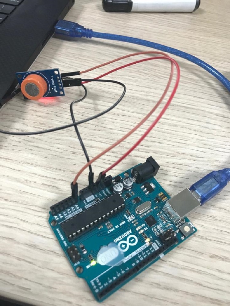
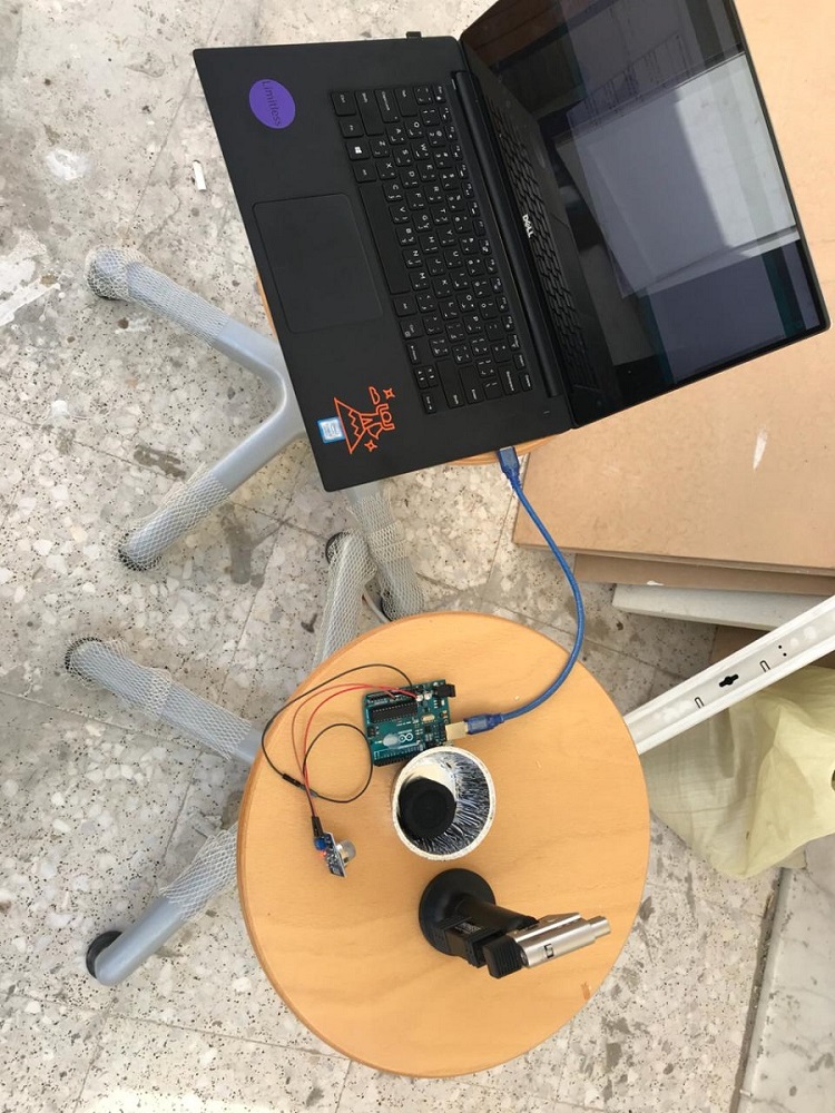
I test the sensor with Arduino UNO I want to make sure that my sensor is working so I can design my board with input and output devices on the same board. That will help me to finish two-week assignment faster.
I found another sensor which is MG811. This sensor really turns my life hell. There is not enough information about this sensor even the datasheet does not have the description of the pin output. there are four pins VCC, GND,Aout and Dout. I can understand that Aout refers to the analog output and Dout for digital output. even thou the reading from this two output does not make any sense. I used lighter to test the sensor, but the sensor does not respond and there are no changes in readings, besides the numbers are not stable. I search again hoping to find so solution and I found that I am not the only one how complained about this sensor.
Any way Hasim told me Wednesday morning that he ordered an MQ2 sensor. I was really happy that finally my suffering will end.
I replaced the MG811 with MQ2 and I search for a program and I found one here
I upload the code to Arduino.
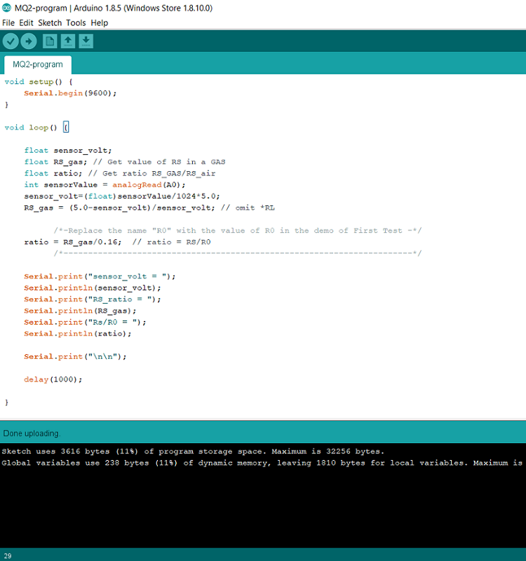
I tested and I was able to see the changes.
Ro – The resistance of the sensor in clean air
Rs – The resistance of the sensor when it is exposed to any of the mentioned gasses
Sensor output in clean air = 2.06
The ratio = 1.43
sensor output with smoke = 2.65
The ratio = 0.89
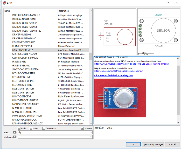
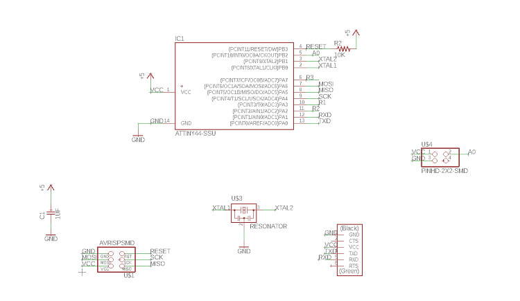
I used Eagle to design my board. I had to download a library for my sensor and I found this library.
and I found exactly schematic or footprint of my MQ2 sensor.
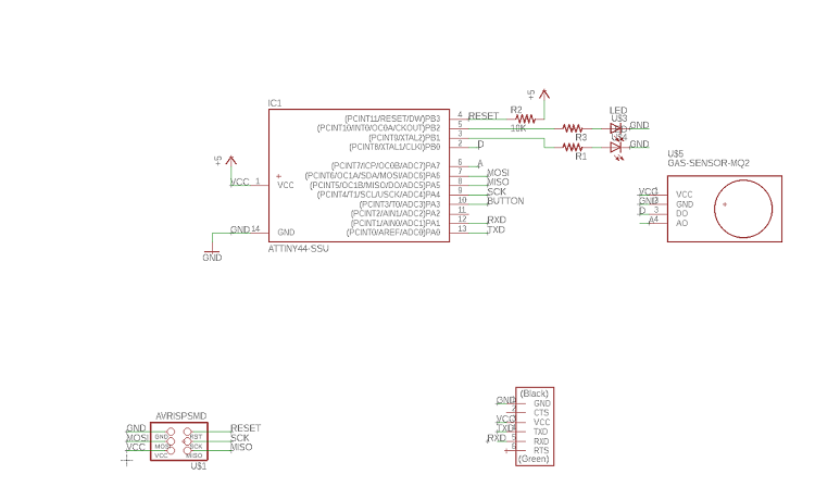
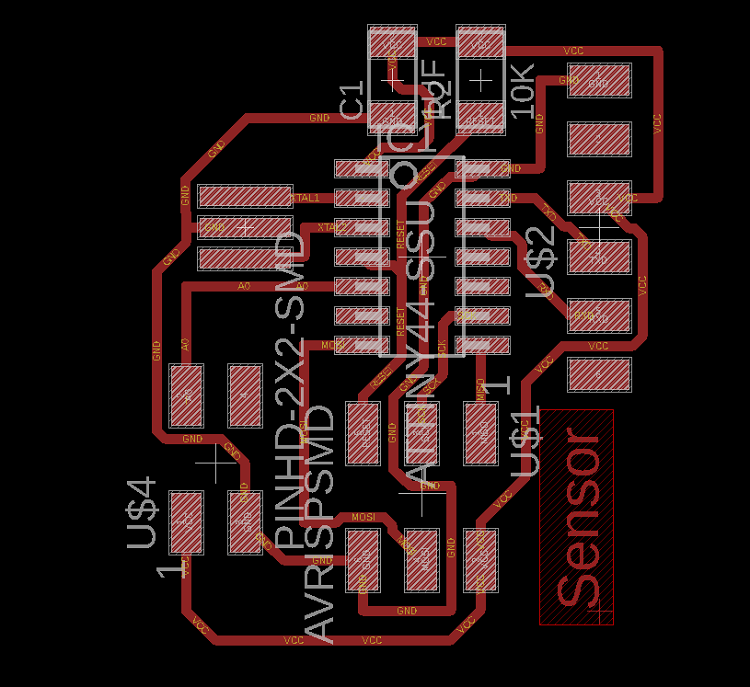
I used the schematic for my assignment week 7 Electronics Design and I add my sensor to it. I milled and soldered the board. when I reached the programming part the AVRISP was beside my sensor headers and there was not enough space for the sensor to be connected but the RGB led works fine.
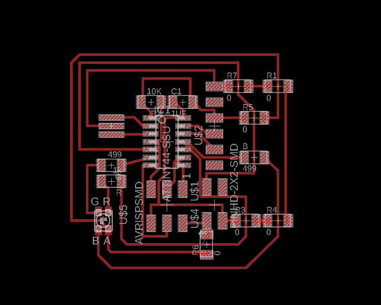
Anyway, I did another board and I take on considering the space between component. but this time the board does not work I don't know why. Then I decided to design a board only for the sensor.
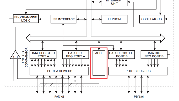
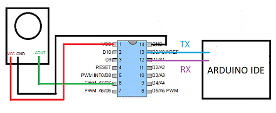
I connected the sensor to pin 8 physical pins 5 in Attiny44 and the Attiny did not read the sensor I don't know why. I felt that something wrong with the pins so I add jumper wire that connects the sensor to pin7 physical pins 6 and then Attiny as able to read the values from the sensor. My global evaluator Steven Chew gave me the advice to check the ADC for the ports. I don't know how to explain here is a webpage that has a good explanation . ADC is only connected to port A as is shown in the datasheet and I didn't pay attention to it.
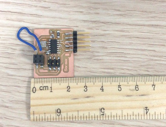
This is my connection.
I updated this code into the board.
File
ProgramPCB
Schematic
Other activity
I get surprised that FabLab staff and the FabLab manager Ms. Marwa prepared a mini party welcoming us back after one week break. I didn't expect that they will bring some cakes. Maybe because I never been in place that is good as FabLab UAE. Anyway in glad that I'm in this place surrounded by this staff and friends.
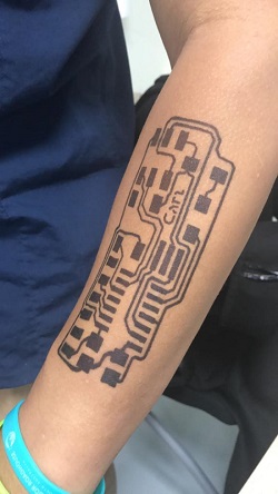
Is there a good and happy news there is always sad news besides it. this week we had to farewell Carl. he left was to continue in Iceland. I wish him all the best in Iceland and I hope to meet him again in Paris in the conference. He mills his board in his hand by henna before he leaves with help of Zahrah.