Week 8:
Computer-Controlled Machining
- Making Steps -
I will show below the steps of making the mini-table. Well, as usual, I didn’t use any new tool in designing and extruding except in Fusion 360. and yes I’m really good in using the parameter feature in Fusion now than before. I prefer to design on Fusion 360 - you can download the file of the design on link at the end of this page- Testing the model on easy and usable material is always good idea,
So, I went for a cardboard and to see how my table will look like in term of the actual size, how strong joints can be, and what areas can I add or modify in my design.
I did couple of samples by laser cutting machine with varied sizes and shapes too.
Finish from the cardboard part.
After each of us did the cut in laser machine, our instructor Wendy discussed each model and how we should modify it to move to the next step of the make -CNC cut-
- Kerf testing -
To find the correct the kerf or the difference in slot size in week 4 "Computer controlled Cutting week" we as a group did a task to find out this kerf using the cardboard, one group took the task to find the kerf for cardboard thickness 3 mm and the other took same material but 6.5 mm.
So regarding material's thickness with changing laser sittings which are Speed, Power and PPI our group did about 10 tests with 3mm cardboard changing these variables in order to make a perfectly fitting press-fit kit. for more details about the tests results on kerf please see the link of the Kerf Testing group assignment for "Computer controlled Cutting week4"
- What is the best number we get from this test? -
It is 0.3 for the cardboard material with 3 mm thickness which me and my group did.
However, in this week's project the used material is for sure different, so I'm using plywood for the table so as a first cut I did use the same kerf for 0.3 for 12mm wood piece and the joints was not tight enough which then I minimize the slot size to 0.2 from it I had an excellent press-fit tight table with just a little sanding in some places I reached to a very good and strong jointed coffee table.
- VCarve- ShopBot software -
Here is another interesting new software I'm learning this week 😊. Wendy gave us a session on how to use vcarve Pro - ShopBot Edition 8.0
So, I wrote the steps of making a file on the vcarve after finishing the design.
Steps I follow to creat my vcarve file:
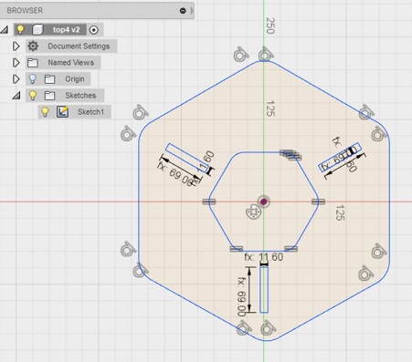
Bring your DXF file you made/ create new layer and name:
a. screw = create vector, circle and choose the radius or diameter.
Put the holes where you want as long as it's not in the same place the mill bit runs in the pocket or cut line. Be very careful, put the screw in different layer that cannot be accidently selected in the next path.
So regarding material's thickness with changing laser sittings which are Speed, Power and PPI our group did about 10 tests with 3mm cardboard changing these variables in order to make a perfectly fitting press-fit kit. for more details about the tests results on kerf please see the link of the Kerf Testing group assignment for "Computer controlled Cutting week4"
- What is the best number we get from this test? -
It is 0.3 for the cardboard material with 3 mm thickness which me and my group did.
However, in this week's project the used material is for sure different, so I'm using plywood for the table so as a first cut I did use the same kerf for 0.3 for 12mm wood piece and the joints was not tight enough which then I minimize the slot size to 0.2 from it I had an excellent press-fit tight table with just a little sanding in some places I reached to a very good and strong jointed coffee table.
- VCarve- ShopBot software -
Here is another interesting new software I'm learning this week 😊. Wendy gave us a session on how to use vcarve Pro - ShopBot Edition 8.0
So, I wrote the steps of making a file on the vcarve after finishing the design.
Steps I follow to creat my vcarve file:
Bring your DXF file you made/ create new layer and name:
a. screw = create vector, circle and choose the radius or diameter.
Put the holes where you want as long as it's not in the same place the mill bit runs in the pocket or cut line. Be very careful, put the screw in different layer that cannot be accidently selected in the next path.
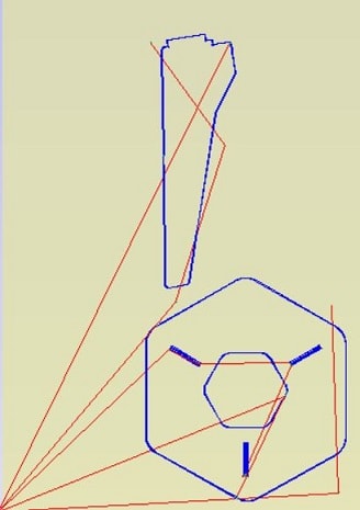
Below you can see where I put the holes.
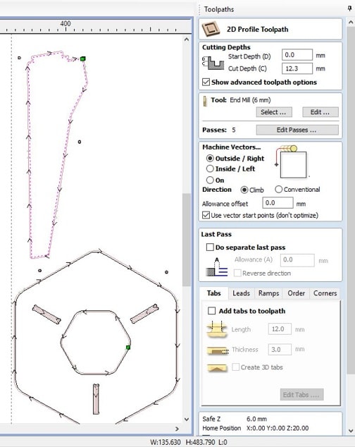
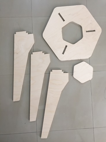
Toolpath and this feature for cutting out the parts and this is the pink dotted line. Also If you notice the small green squares are called tabs so I added them for each part to hold it in place after cutting the plywood.
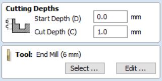
Regarding to cut depth, the wood width I’m using is 12 mm thus, the I cut depth I put is 12.3 to make sure it cuts all the way through.
- Then go for pocket to cut out your slots for the table legs:
b. pocket: add the slots of the top table to the pocket layer by window on slot/ wright click/ move to pocket layer.
To make sure just select all your object and see which one is selected.
For creating “dog bones”:
1.edit object
2.create fillets
Dog bone fillet
Fillet/ tool radius / I chose 3 mm
* "IF" you couldn’t do fillets. Go edit object/ create fillets/ choose dog bone fillet/ tool radius (I put 3) mm.
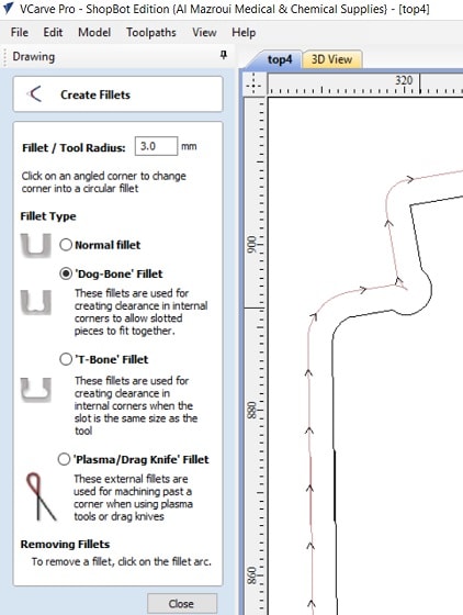 So we use fillets feature for the mill bit to successfully pass through the edges while maintaining right angles in cut.
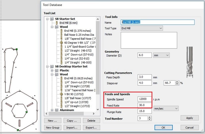
As for the tool path, I used the following parameters, 6mm flat end mill withe cutting depth 3mm and 4mm stepover spindle speed 12000 r.p.m, feed rate 30 and plunge rate 15
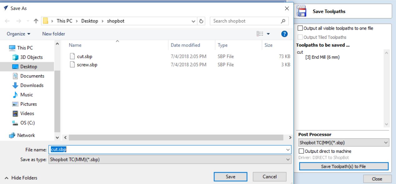
Now, to cut on the shopbot, the toolpath must be exported from crv to be ready for the cut by ticking the toolpath you need to cut and then save icon/ make sure you select mm not inch because our measuring that we uses is mm/ save the toolpath to file/.sbp type of file..
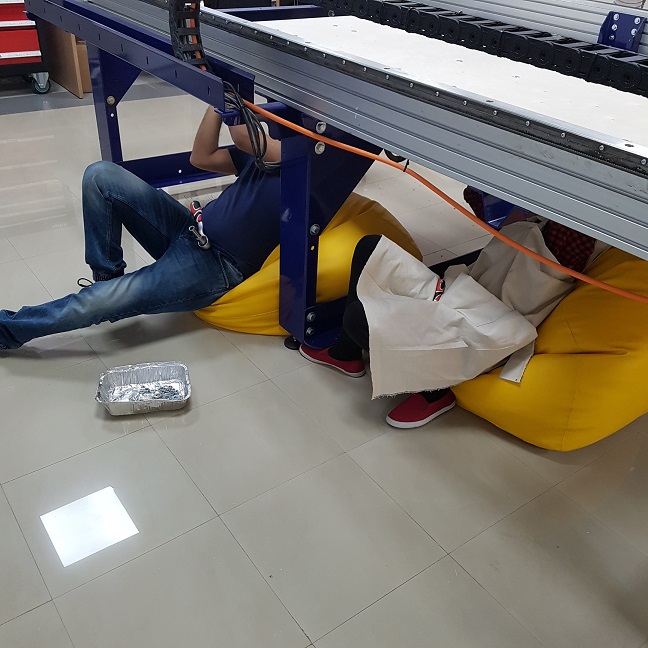
- Welcome on board -ShopBot Room-
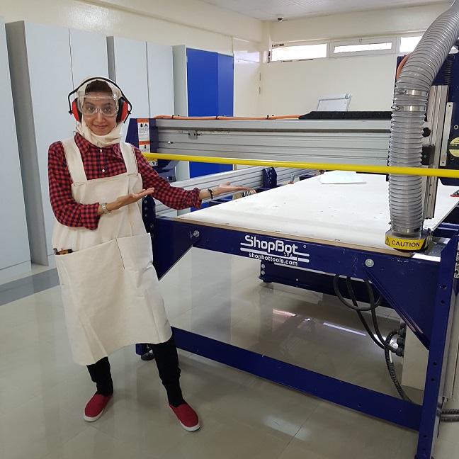
Well, first we put the plywood and clamp it to the bed, and make sure the clamps are away from where the spindle is going to run. The mill bit also had to be firmly tightened but not too tight in place, and all 3 axises had to be positioned at zero. The extraction has to be on to clean the dust off while you're cutting.
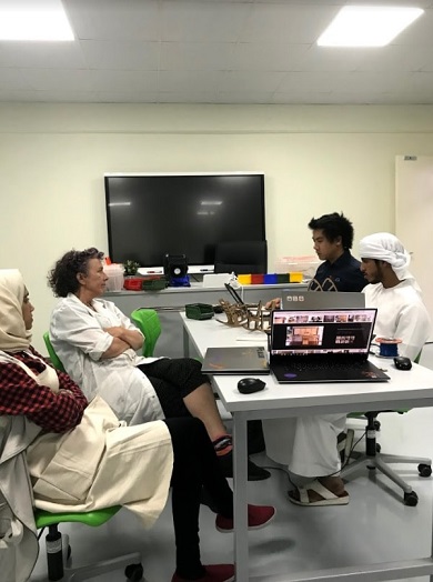
Thanks to Wendy's help, I was able to do this smoothly and was ready to run the job.
Here, I had a good time helping my instructor setting up the bed before we start cutting my table.
Steps for saving the file and opening in shopbot software
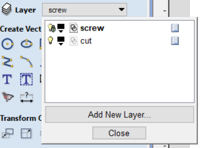
To save the file as sbp. file which is required to be included in the shopbot program, make sure of the following before you save:
- Select only the layer that you want to save like in the image I did select the "cut" layer.
- Save Toolpath
- Choose shopbot TC(MM)(*.sbp)
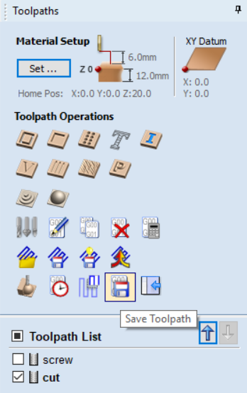
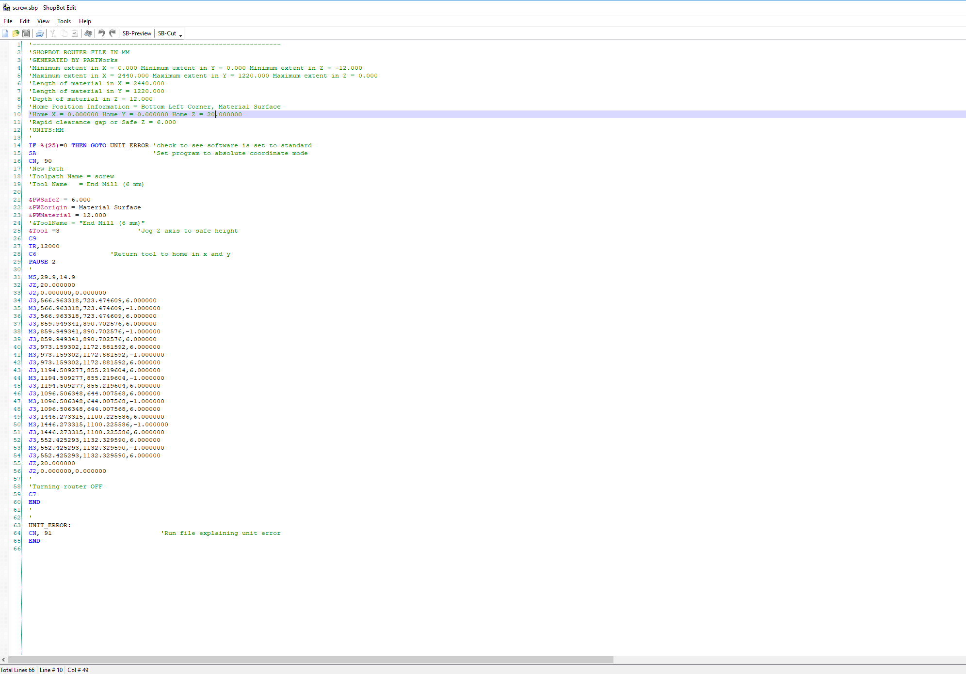
Wendy asked me to open the file in the shopbot so what I did is, I double clicked the vcarve file as it was the way of opening the file and this is what I get!! However, this page was full of explanations about the file, and she began explaining the information on this page. She asked me, is there any information you think is useful or you can understand through your reading of the text? I read the lines and found that this page already contains file information like the width, length and depth of the material used, information about the toolpath, end mill, and many things so you can have a look at the image and for more details about the file.
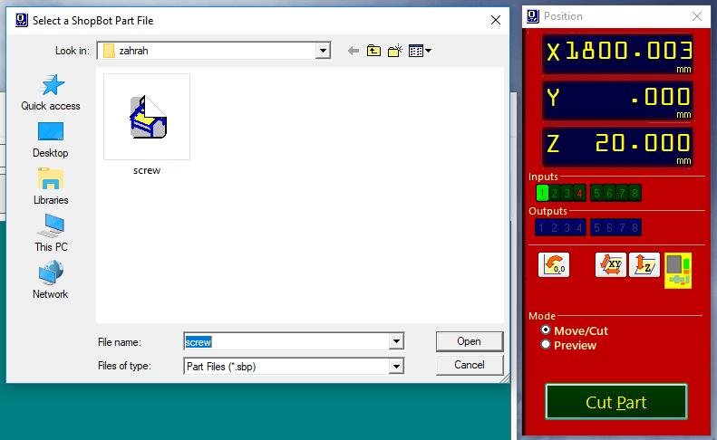
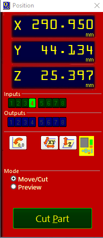
From here you can open or bring the file from "Cut Part" then select your file.
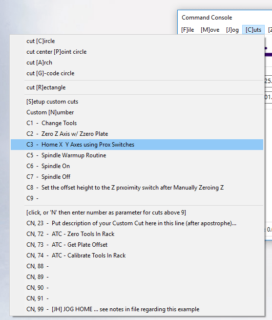
Now zeroing the X and Y axis. Go to [C]uts and choose C3- Home X Y Axis using Prox Switches, this is for X and Y axis. Same things for Zeroing the Z Axis but you choose C2- Zero Z Axis w/ Zero Plate.
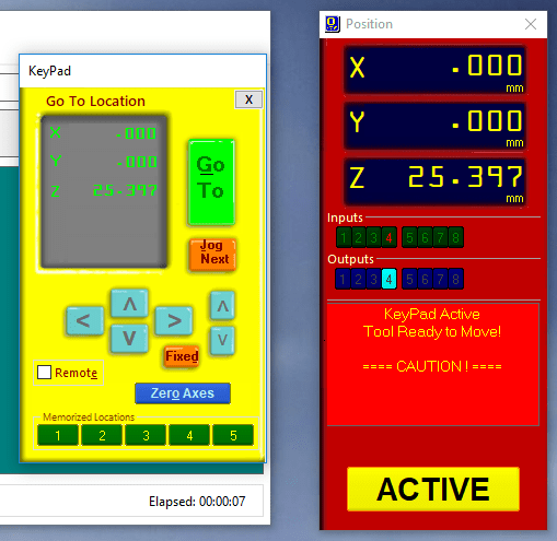
Milling the plywood, and after double check I pressed the start button and run the plywood.
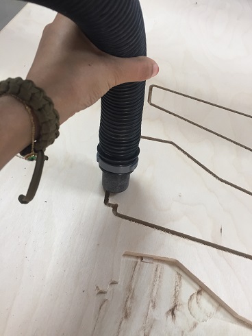
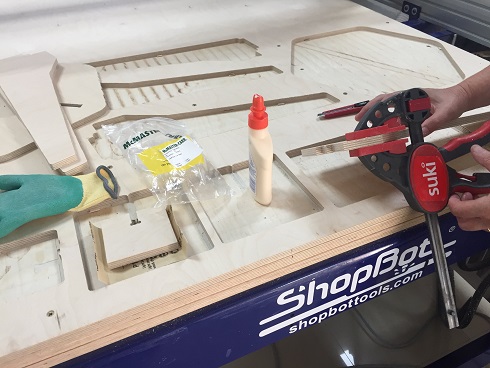
I used the vacuum cleaner for the small pieces of wood left on the surface to start the step of removing the parts from the base.
The chisel and hammer were used for the tabs to remove the cutted piece.
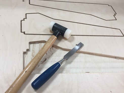
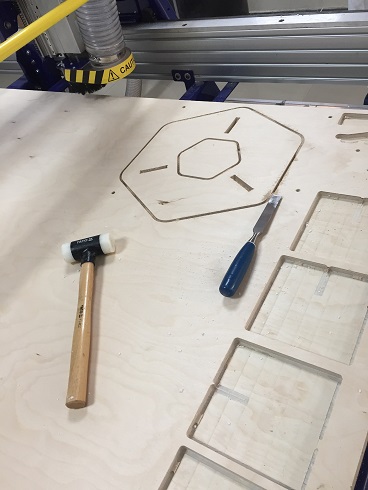
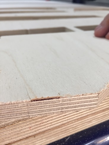
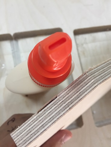
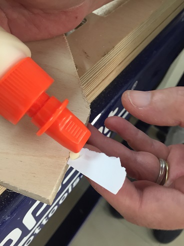
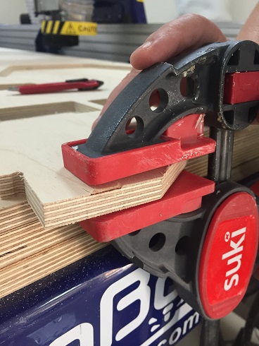
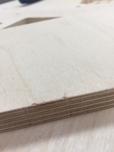
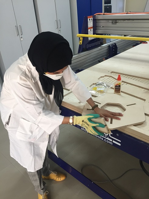
While I’m trying to remove the parts from the main big piece of wood using the hammer and the chisel to cut the tabs, one layer of the plywood has split, So, me and Wendy did fix this little issue by using a wood glue and clamps to keep pressing the splited wood together.
Using the sand paper for smoothing the edges of the table
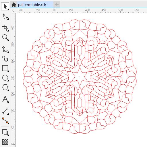
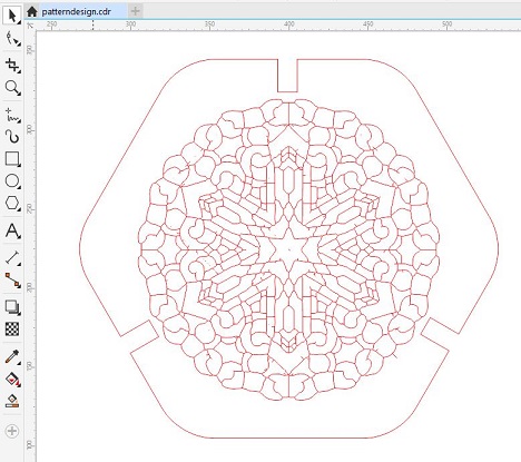
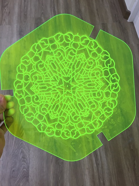
I added an acrylic part to my wooden table to give nice look... So Wendy’s idea was to put some engrave or decoration by doing that in laser. So, I download a draw from google and then modify it in CorelDRAW. and you can't imagine how much I loved the outcome of this part!!!
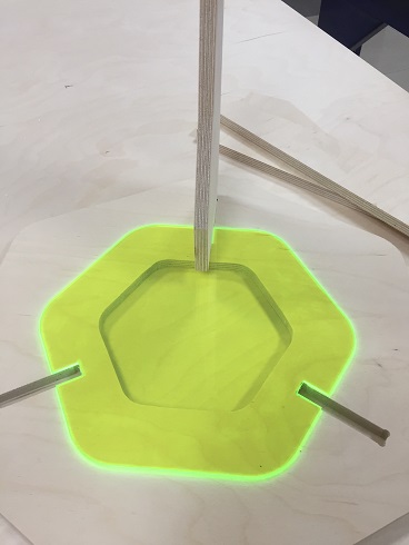
Let's have a cupper on this cute little coffee table ^__^
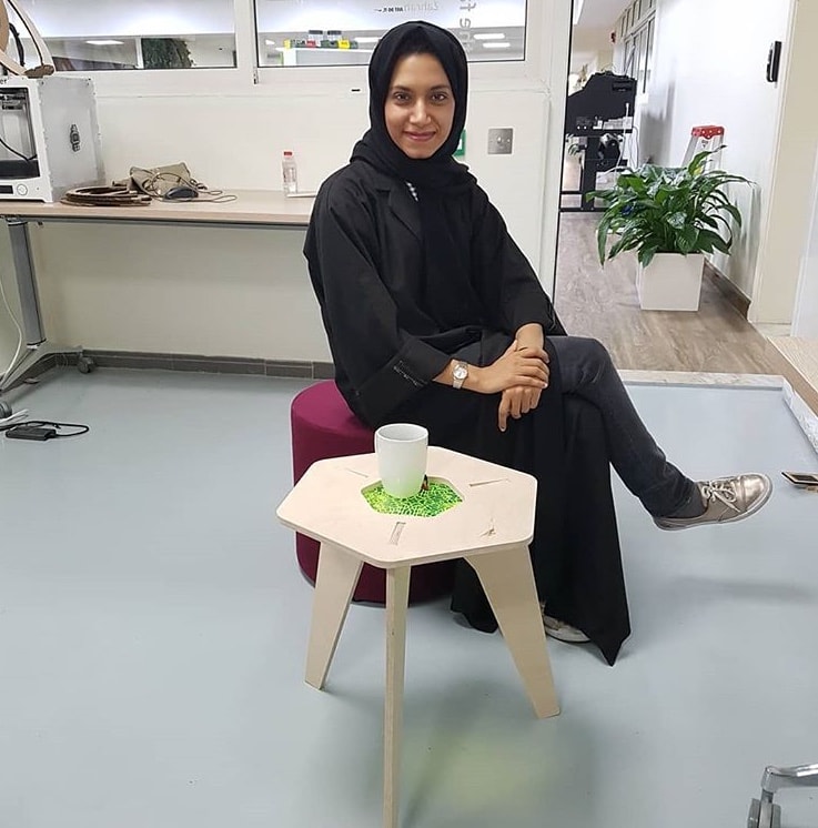 ** Thank you Wendy for taking this fab. hero shot of me with the table X
I learned how to...
- Use the ShopBot (large-scale CNC milling machine)- Design and build wooden furniture :)