Laser Cutter
Machine description
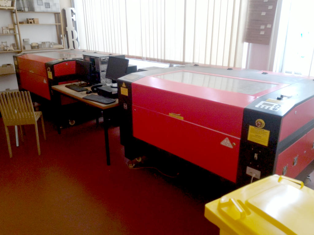
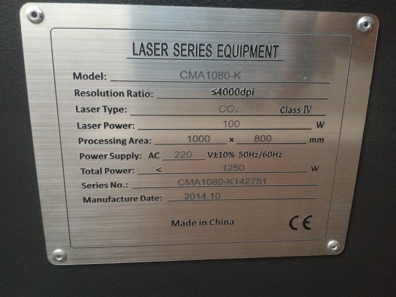
Our laser cutter is a CMA1080-K from Han's Yeming.
| Model | CMA1080-K |
| Laser type | CO2 |
| Laser power | 100W |
| Processing area | 1000mm x 800mm |
Testing materials
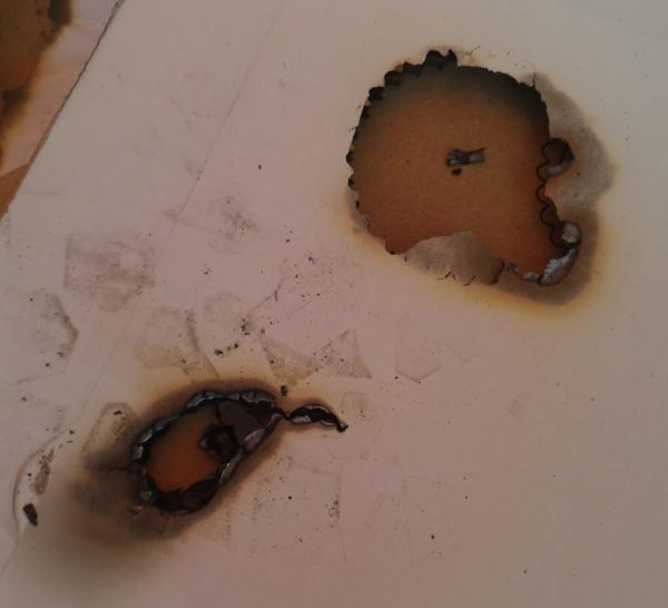
We collected some thick carboard boxes in our trash bins, and we tried to cut it with the laser cutter.
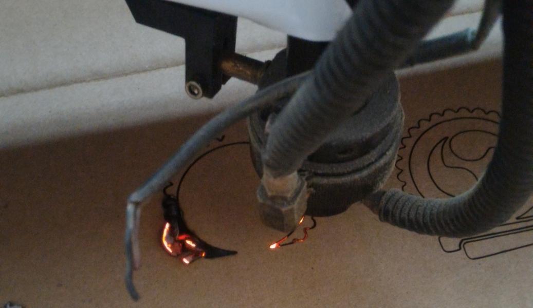
Testing the laser-to-object distance and power parameters
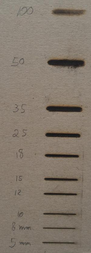
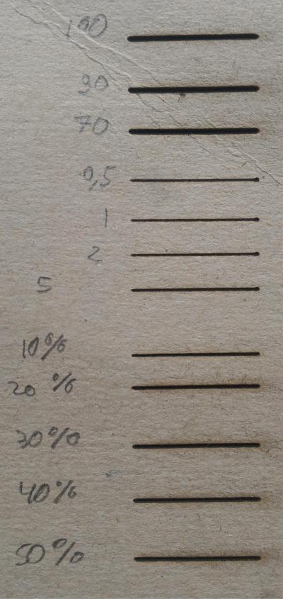
As our laser use procedure is already quite well known at the FabLab ULB, we would like to test thos values. As an exercise, we just traced very simple 2.5cm lines at 20m/s, with different power (distance 8mm) values and placing the head of the laser guide at different distances (60% power level). We wrote the values directly on the cardboard.
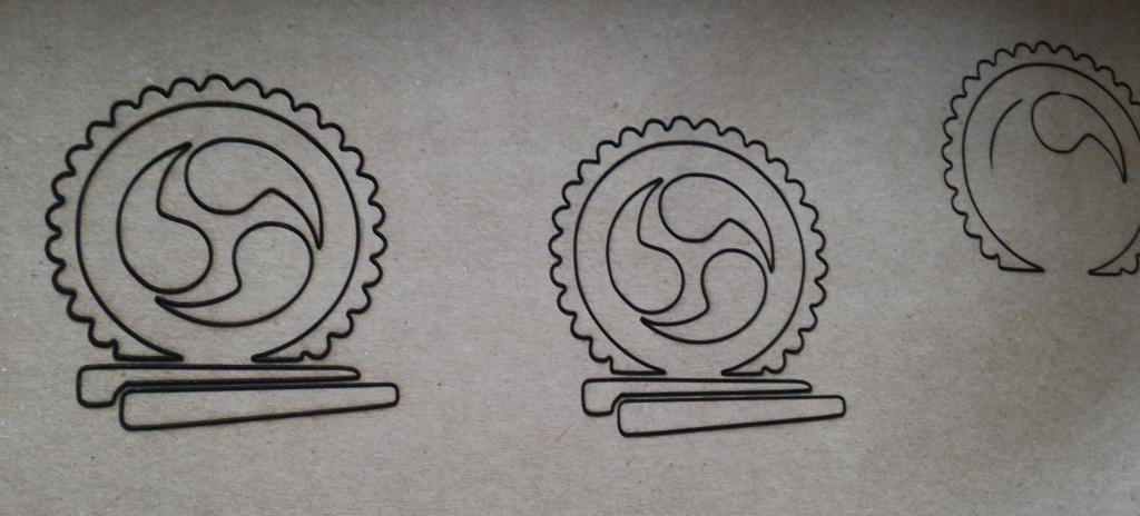
As you can notice, the best value (depending on your goal,... of course) for the head-material distance is at 8mm, as required in our procedures. Going to close will enlarge the line and moving the head away will enlarge. You may notice it will also "dilute" the beam power, as the beam wasn't able to cut through the carboard and even nearly didn't burn it at high distances (100 mm).
About the power, you may also notice that the kerf is slightly different depending on the used power. We don't have a clear explaination but we think it should essentially be due to the fact that the energy we bring is more important and that the material will then burn longer and progress slightly into the material.
Testing the kerf
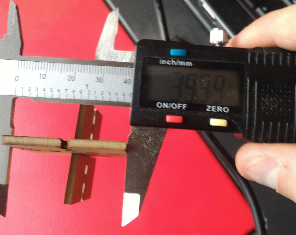
As Victor already did this group assignment last year and that Nicolas created an OpenSCAD script taking kerf into account, we tested it quite easily. This work was already done by our FabLab team last year so we already had an idea of the actual kerf.
We placed the head at 8 mm (obtained before) for this section.
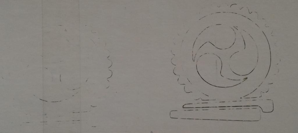
We created an OpenSCAD file with the VIG Pieces Generator, on Nicolas webpage.
Instead of cutting a piece with a target dimension and then measuring the piece, we used the "kerf" parameter of the file generator : among them, one should be the right parameter, so let's find out!
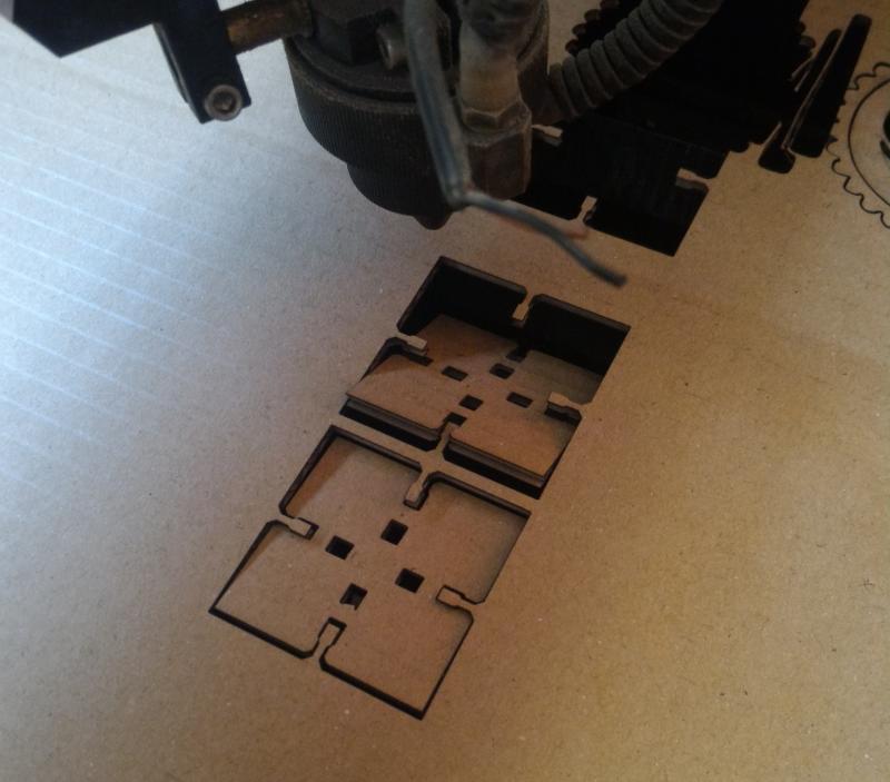
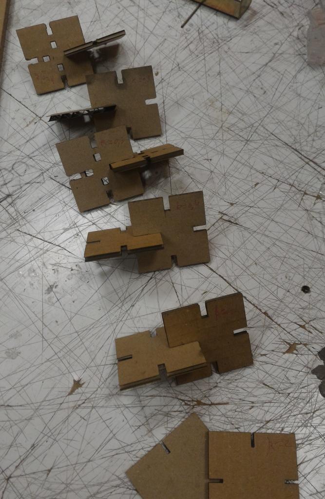
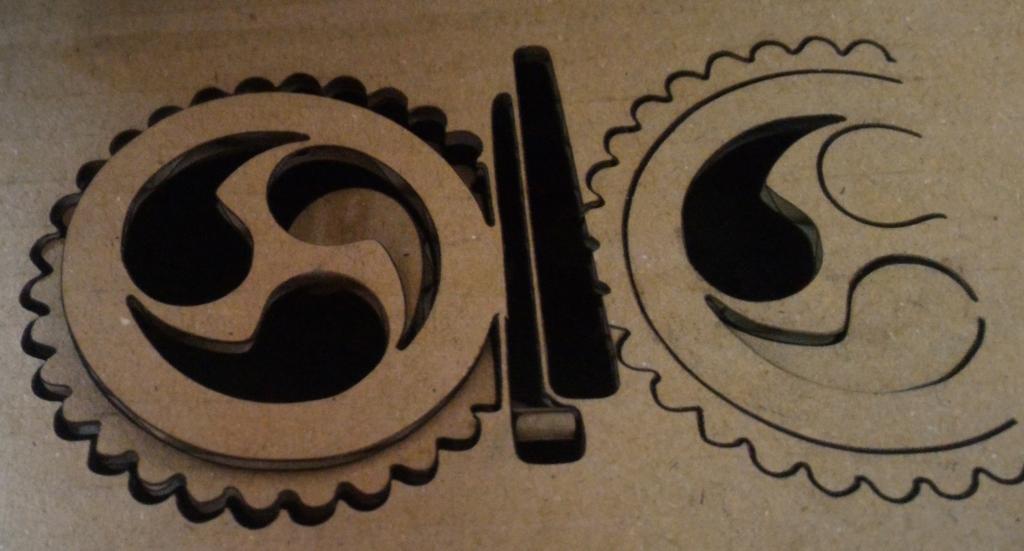
k = 0.3 simple joins and "with jaws, non blocking", k=0.1 k=0.4 and k=2. High (> 0.2 kerf values made the pieces difficult or impossible to press together while low values (< 0.1) made the join too loosy.