
This week I had to communicate two different boards. The first thing I did was attempt to communictate two satsha kits using the serial ports. This is why, I first used two Arduinos to test the connections and the code. In the picture, you can see how I connected one arduino to a push button, one to a LED and how I interconnected them through the serial port. I connected RX to TX and viceversa. I also had to interconnect the GND pins.
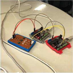
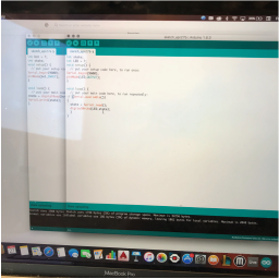
I then wrote two pieces of code. One for the "sender" and one for the "receiver". The code is pretty basic: The button is connected to a digital pin, which reads its state. The processor sends the "state" through the serial port (TX) to the other processor (RX). This processor digital-writes the state to the LED connected to a digital pin.
Given how it worked with the Arduinos, I modified a Satshakit, adding a LED and a Button in the same digital pins and attempting to upload the code. Unfortunately, eventhough the bootloader burnt correctly, I could not upload the code to the board. I kept on getting the message "CONNECTION MISMATCH". This sort of bummed me out, because there was really nothing wrong with my board, the connections were ok, I had not accidentally interconnected any two traces, and the bootloader burnt correctly. Thus, I decided to change the approach with which I was tackling the assignment and started working on the hello.bus network.
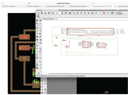
The first thing I did was analyze how the boards worked and re-route them. The hello.bus consists of a bridge (which is basically the master) and any number of nodes (which are slaves). I decided to use only one node. I started by modifying Neil's bridge board.
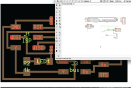
And routing it...
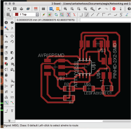
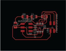
I then did the same for the node schematic and board.
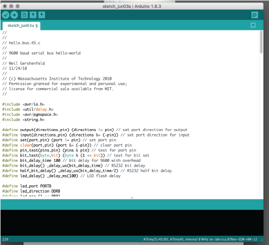
Finally, I modified Neil's code. The same code must be uploaded to both boards. There's a line in which the software identifies the node with : "#define nodeid: 0". This line must be changed for each board. The bridge is node 0, while the rest of the nodes are 1, 2, and so on respectively. I uploaded the code to both my boards and connected them.
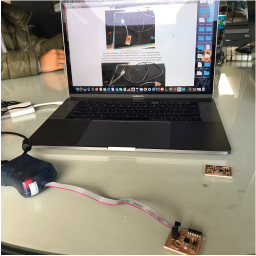
I checked other people's documentation, just to make sure that everything worked out properly, and it did!! There's a video below.
My files can be downloaded with the following links: