This week's assignmet was to experiment with 3D printing and scanning technologies.
The first part of the assignment was testing the 3D printers. I decided to test the Makerbot Replicators + because they are the ones I'll be using the most. I obtained the file from the "constraints" link, located in the archive, and it led to this thingiverse page with the test. Fabrico, Nicolas and I 3D printed the 7 pieces on 2 identical Makerbot Replicator +.
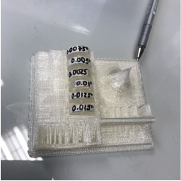
We found that the tolerance for our 3D printer is exactly 0.01 inches, or roughly 0.25 mm, which is what we had been using at work. Any more tolerance and the pieces fit loosely, any less and they just won't fit at all. This will be useful for my final project, when I print the grips for the water tanks.
I wanted to create something that could not be manufactured using substractive technologies. Therefore, I decided to experiment with Grasshopper and make a Voronoi-patterned cast for an arm.
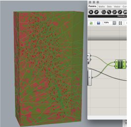
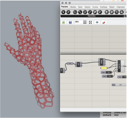
I downloaded an .STL file of an arm, and used it as a reference for crearting the cast. In retrospective, I could have 3D scanned my arm and used it as a reference, but I did not think about it at the time. The first thing I did was insert the .STL and generate its bounding box, while populating the geometry with points.
I then generated a 3D voronoi within the bounding box, using the points I created in the surface.
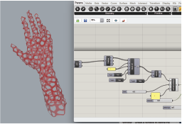
I intersected the Voronoi with the surface to get the pattern which would form the cast. In case I didn't like it, I could change the pattern by adjusting the number of points and the seed with which they're generated. These parameters are inputs for the "Populate geometry" component.
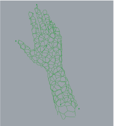
Then, I generated polylines from the intersection, and scaled them according to a variable parametr within 0 and 1. I chose 0.7. This generated the "thickness" of the cast.
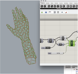
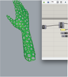
Now that I had these two shares of curves, I lofted them and obtained a somewhat rough idea of how my cast would end up looking like:
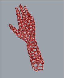
I wanted to soften the surface and then thicken it, thus obtaining a solid. In order to do so, I had to download the weaverbird plugin for grasshopper, which only works with meshes, so I had to generate a mesh from the surface I had.
I then used the weaverbird component "Catmull Clark subdivision" component to recalculate and soften the surface
Finally, I used wbThicken to "extrude" my cast outwards and I obtained my finish cast.
After generating the model, I baked it, exported it, and sent it to the pirnting environment. At my lab, we have a lot of makerbot printers, so I used the makerbot printing environment.
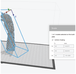
First, I had to reposition the arm. I used the option "Set face on build plate". This option, allows me to select a face, and decide on which position to place it. I chose the face which was closest to the elbow and placed it at the bottom of the build plate.
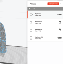
Then, I selected a printer. Because of the size of the model, I chose a Z18 makerbot printer.
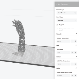
The next step was deciding the printing settings, these will determine things like printing time, but also model resistance and hardness. I used this link as a reference for deciding parameters. Because it was only a test, I did not care about strength, only speed, quality and cost, so I used the following parameters:
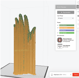
Finally, I needed the software to calculate the print estimates and the preview, so I clicked on the simulation button. Due to the complexity of the mesh, it took about 20 minutes to calculate the printing time. It was going to take 2 days, 11 hours and 12 minutes. 2 DAYS
Obviously, I wasn't about to just go and use a 3D pinter for 2 and a half days, so i had to come up with a different model. I decided to do the same vornoi pattern on a simpler surface, so I settled for a ball.
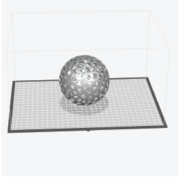
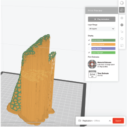
I then followed the same steps as before, except that I used a Makerbot Reploicator + rather than a Replicator Z18. I used the same parameters, and generated the preview. The printing time was, luckily, only 12 hours.
I exported the file and saved it to my flashdrive. I sent the file directly from the printer using its USB-port.
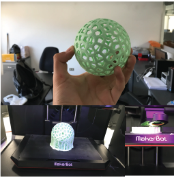
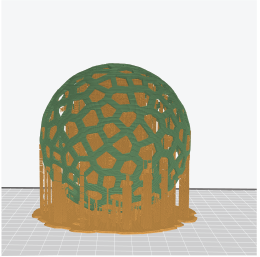
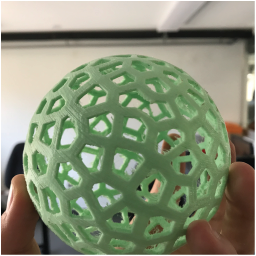
FInally, after about 2 hours of support removal, this was the result:
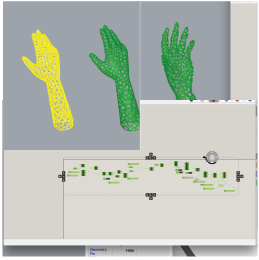
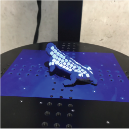
I tested the scanner available at UTEC during this part of the assingmet. It's a structured light scanner, which uses a rotating plate as a way of getting all of the necessary shots of the object.
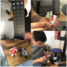
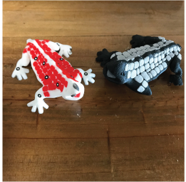
I had to use some targets on top of the surfaces I had to scan. Since these targets were rather small, I had to use some tweezers to help me poition them correctly. I wanted to compare how the scanner would react to colored surfaces, so I used 2 identical models (regarding shape), except that one was white with red spots, and the other one was black with grey spots.
First, I tested the withe lizard.
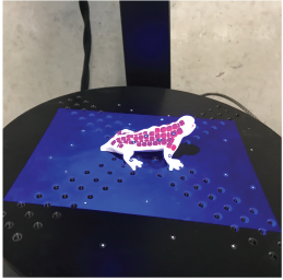
I tried to cover most of the angles, so that I could obtain the most reliable scan, but this is what I obtained:
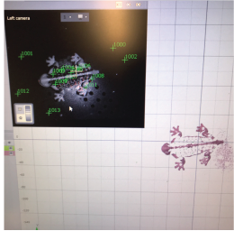
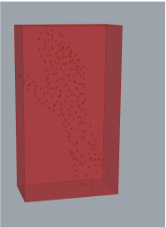
It seemed like the scanner was only obtaining the white "skin", and not the red spots. I decided to try with the black lizard, to see if the results were any different.
After a lot of twisting and turning, the scanner only obtained thew following representation of the objetct:
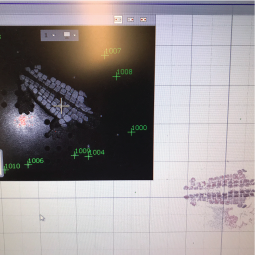
I exported my scanned object and obtained an STL type file. This file can be later modified using CAD softwares sich as Rhino, Fusion 360 or MeshMixer. So, here's what I learned: The structured light scanner works best with lighter colors, specialy those closer to white. It does not react well to fully saturated bright colors, like red, or darker colors, like black. If you want to see some other things I've done with 3D scanners, check my fabricademy documentation for the second assignment: Digitsl Bodies.
Download Files : my files are rather heavy (45 Mb), so i've uploaded them a to a drive. My grasshopper file can be found here.