Wheek 12: Output Devicess.
In this week, for my output device, I used pulse wide modulation (PWM) to control an RGB Led. This program worked on Attiny 45. The output is basicly a piece of hardware that turns signals into physical manifestations. Most common devices include leds,buzzers, motors,etc.
For my final proyect I intended to use two DC Motor controlled with PWM. It is necessary to controll the speed of each motor beacause one motor must rotate very slowly, and the other one must run at a high torque, In order to get the motors moving, big power is needed.
The microcontroller
I used Attiny 45 controller data sheet. This the little microprocesador allows program development on C.
For more information the following link:
https://www.digikey.com/product-detail/en/microchip-technology/ATTINY45-20SUR/ATTINY45-20SURTR-ND/2063205
Fig 1. Microcontroller as shown on DigiKey webpage.
The board I added one led and resistor to indicate the board is energiced.
The output device, RGB Led:
This devices have tree led embedded and the control is made with the microcontroller.
For more information the following link:
https://www.digikey.com/products/en?keywords=CLV1A-FKB-CK1N1G1BB7R4S3CT-ND
Fig 2. Output devices RGB Led as shown on DigiKey webpage.
For the board, I added one led and a resistor to indicate if the board is energized.
The design was made using Eagle program.
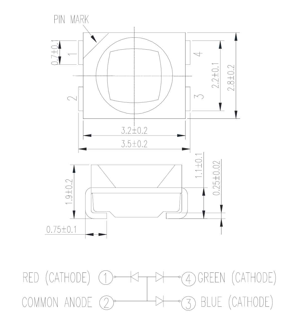
Fig 3. This picture show distribution of the pins: Mark (anode) and tree pin (cathode). This pin RED, Green, Blue.
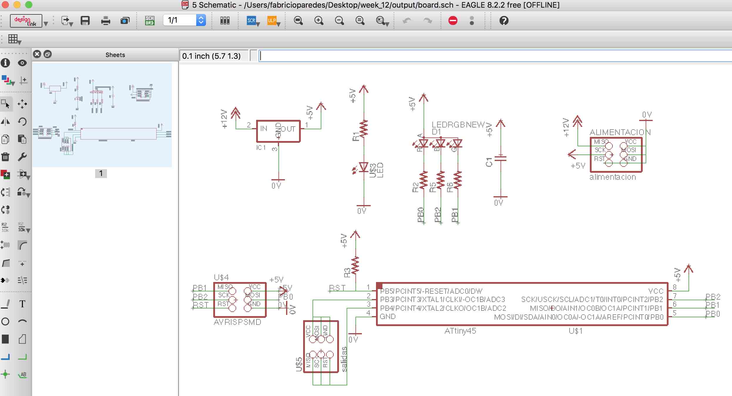
Fig 4. The Schematic on Eagle.
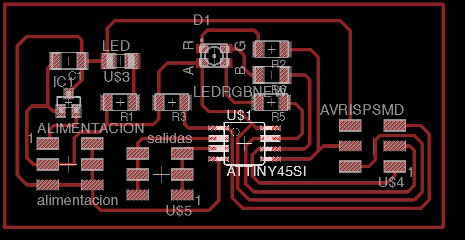
Fig 5. This board have an extra pin so we could read f the PWM signal on the ociloscope.
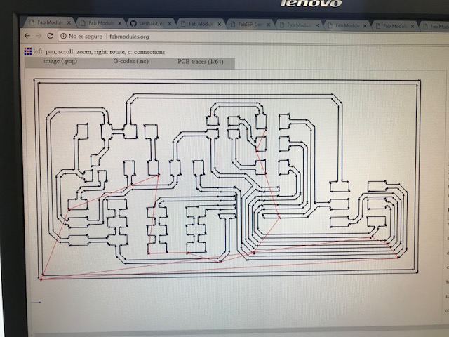
Fig 6. Generate the code on Fabmodules for Modela MDX 540.
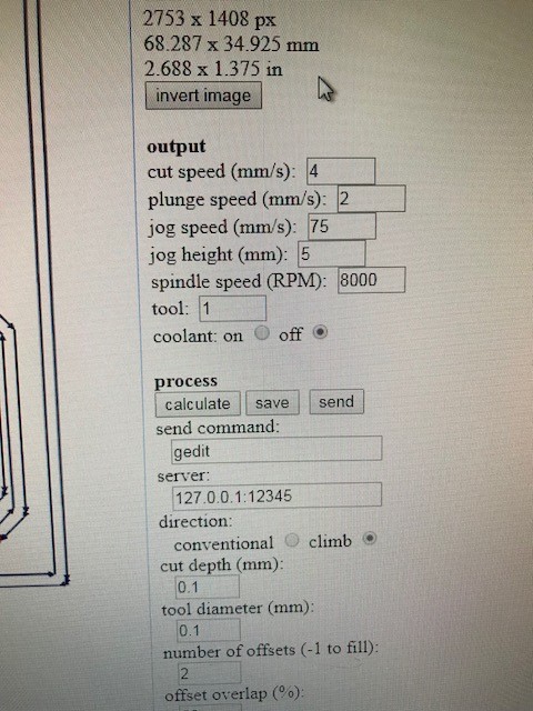
Fig 7. The principal parameters for the process on Modela MDX 540.
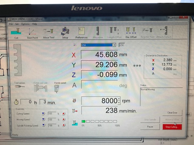
Fig 8. The output parameters during the machining
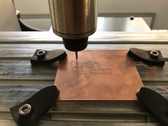
Fig 9. The machining took about 20 minutes to complete on the Modela MDX 540.
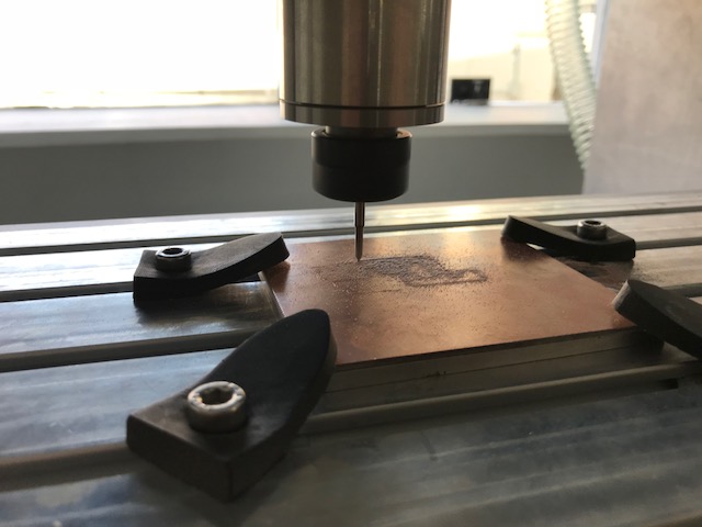
Fig 10. The furnished machining on the Modela MDX 540.
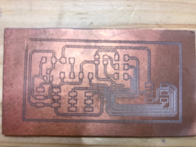
Fig 11. The final board .
The next step was to test the board. In order to do that, I uploaded the firmware to the ATtiny 45. From previous assignments. I learnt the correct workflow of the programming of the Attiny by reading its Data sheet.
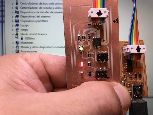
Fig 12. ISPFab to lead the firmware to ATtiny 45
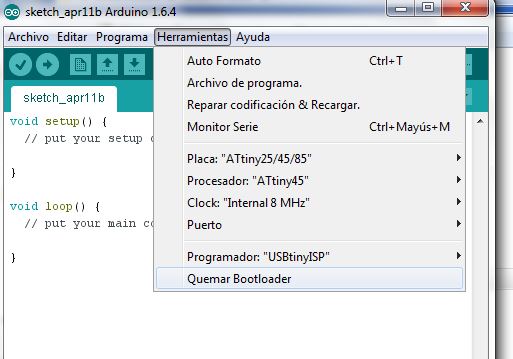
Fig 13. Configuration of the board on Arduino ide 1.6.4.
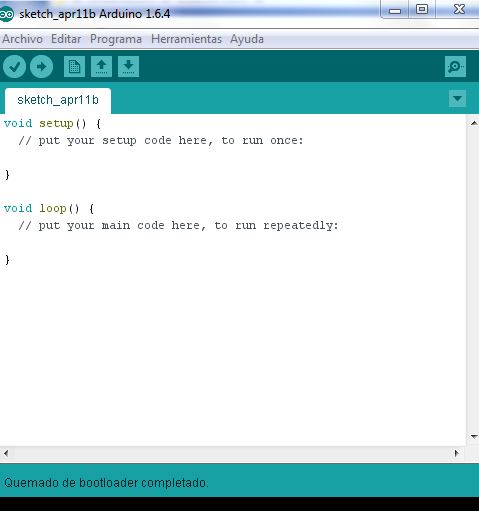
Fig 14. Burning bootloader on to ATtiny 45.
In the academy site, on the directory about output devices, we have some examples of different types output devices. For the RGB Led Neil wrote the hello.RGB.45.c. I downloaded the file and copied it to ide Arduino 1.6.4.Then connect to the FabISP.
Now the firmware now was uploaded to the ATtiny 45.
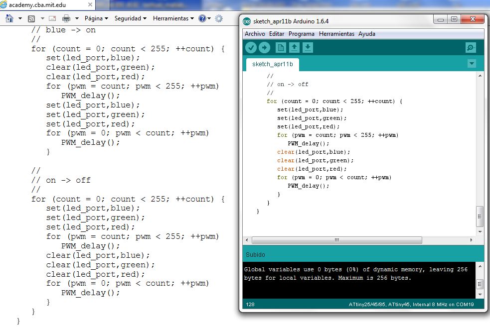
Fig 15. the “hello.RGB.45.c” as shown on Arduino IDE. And uploaded on the ATtiny 45.
Program Attiny with
Neils Code
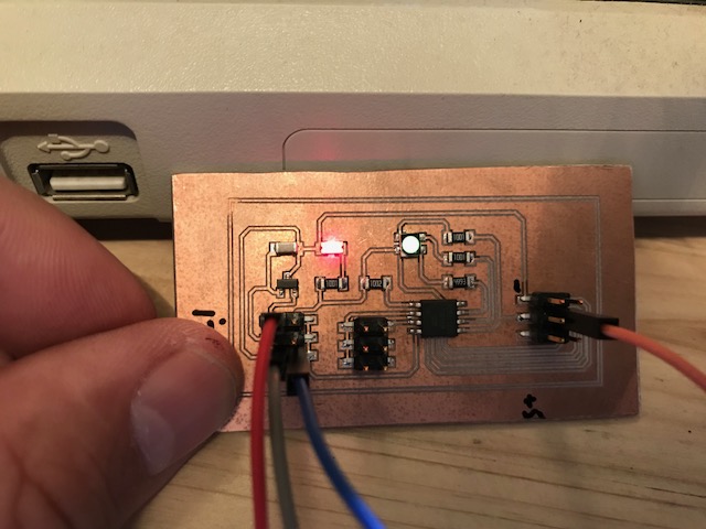
Fig 16. This picture shows the program runing the RGB Led. It turns on. The red light shows that the board is being energized.
In this video, I show the RGB Led working. The colour changes from RED, to green and blue.
Right mouse button to play video
In this video, I show the data from the RGB Led. The wavelength on the oscilloscope shows two signal channel. PWM worked on the board.
Right mouse button to play video
Now I programed the new example with the PWM. I used the Arduino Ide 1.6.4 and the example with a potentiometer attached on pin 3 and the outlet attached to pin 1.
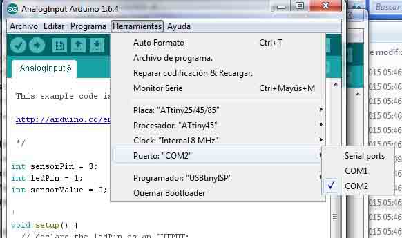
Fig 17. Configured the ATtiny 45 at 8 MHz on the Arduino IDE 1.6.4.
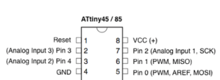
Fig 18. The pin on Arduino Ide for example in my case, I used pin 3 on Arduino which corresponds with the pin 2 on the attiny.
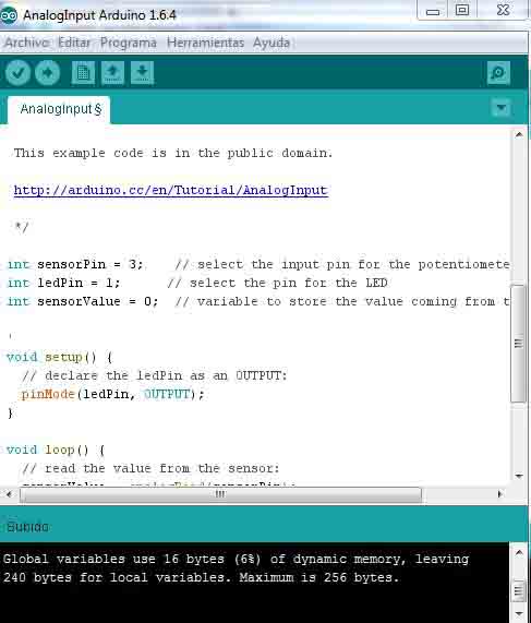
Fig 19. This code was made with the correct pin and then uploaded on Attiny.
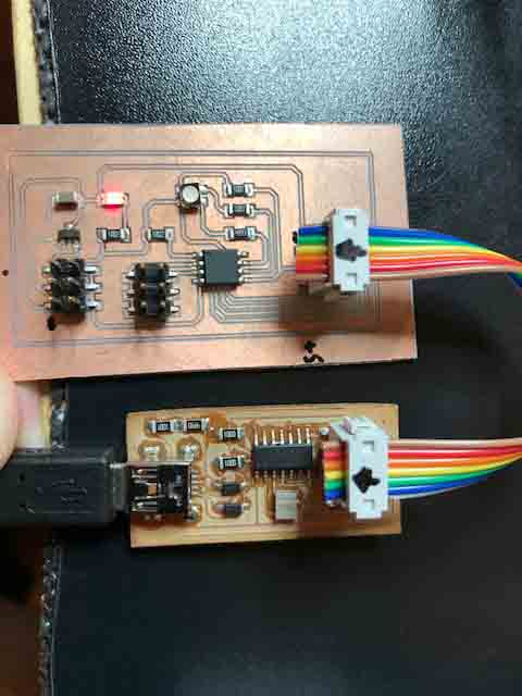
Fig 20. I used FabISP on the ATtiny 45 with windows 7.The red led indicated that the board is being energized.
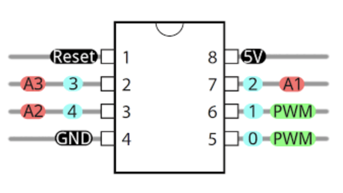
Fig 22. The regulator on the board supplies 5v to the ATtiny 45.
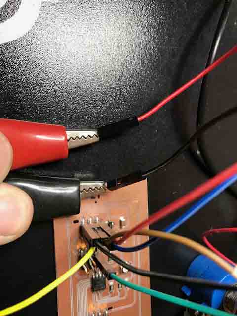
Fig 23.The cable Red had 6V and the cable black is negative from the source.
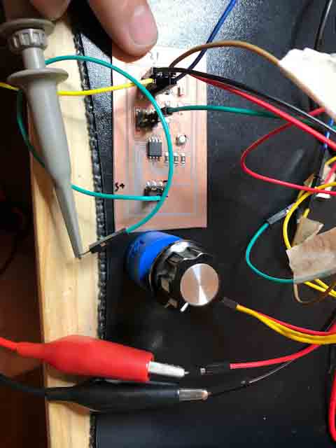
Fig 24. The oscilloscope connects to pin 1 (MISO) outlet and potentiometer connects to pin 3.
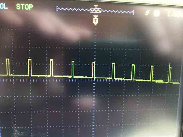
Fig 25. The first signal obtained with the new code.
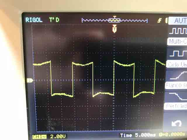
Fig 26. When the I manipulated the potentiometer, the signal changes.
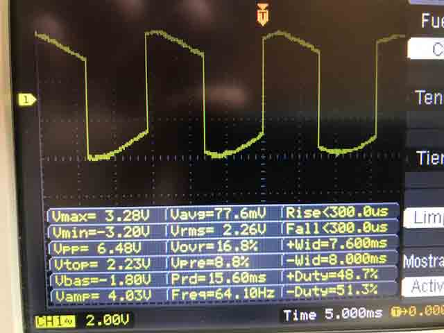
Fig 27. For example when I manipulated the potentiometer, the signal changes frequency to 64.10HZ
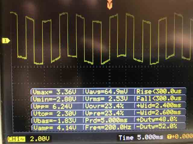
Fig 28. Then, I manipulated the potentiometer and the signal changed frequency to 200.0 HZ
Well, when using PWM to control a period signal for a DC motor, it changes de RPM and the final power on the shaft. The PWM is a classic control strategy for controlling the intensity of some variables.
Download files here:
Eagle board RGB Led
Eagle shematic RGB Led