Wheek 16: Machine Design.
This week our team, Carlos Herbozo, Nicolas Newton and Fabricio paredes built the CNC router we designed last week.
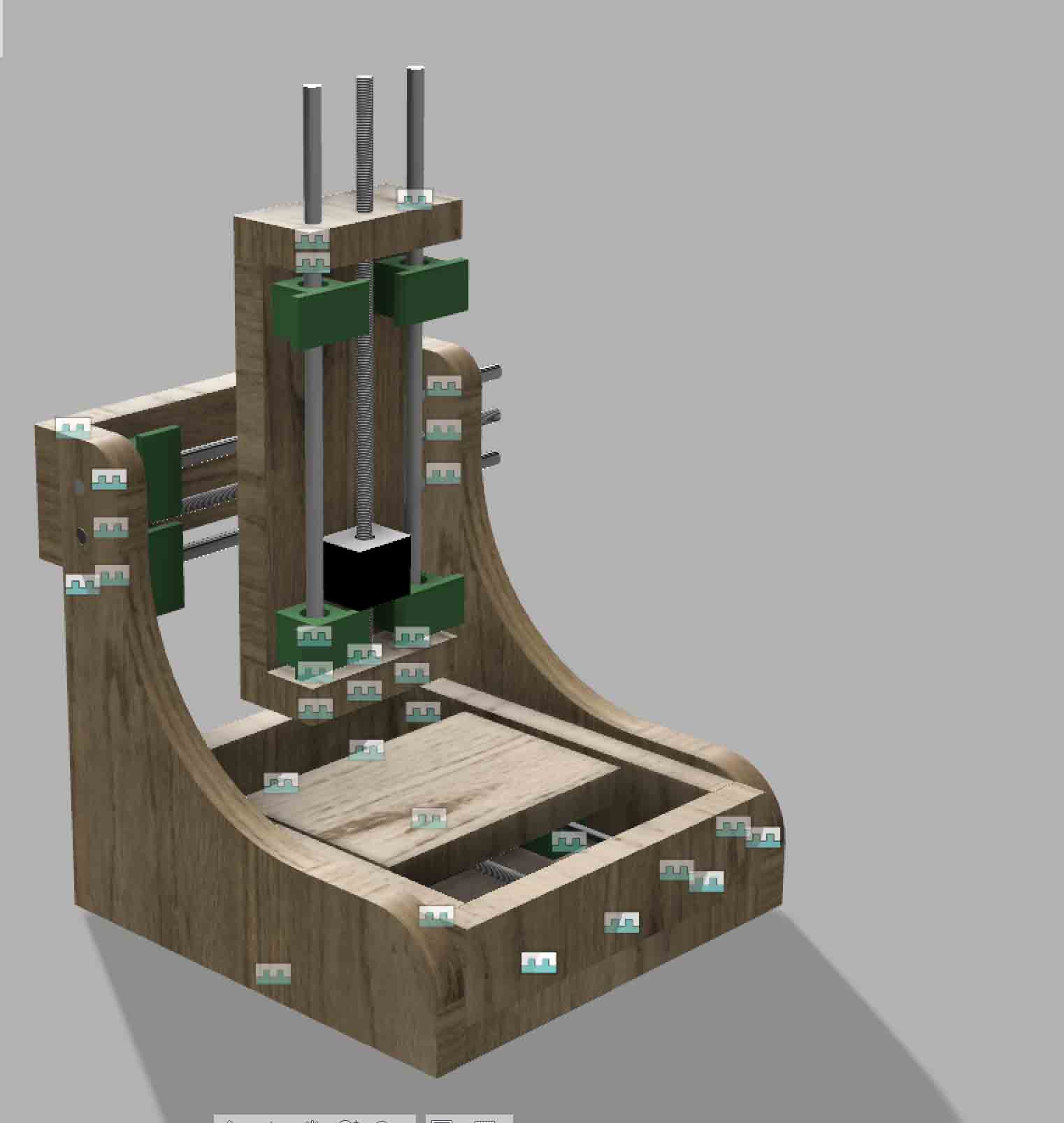
Fig 1. Desing on fusion 360 by Carlos Herbozo
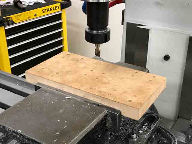
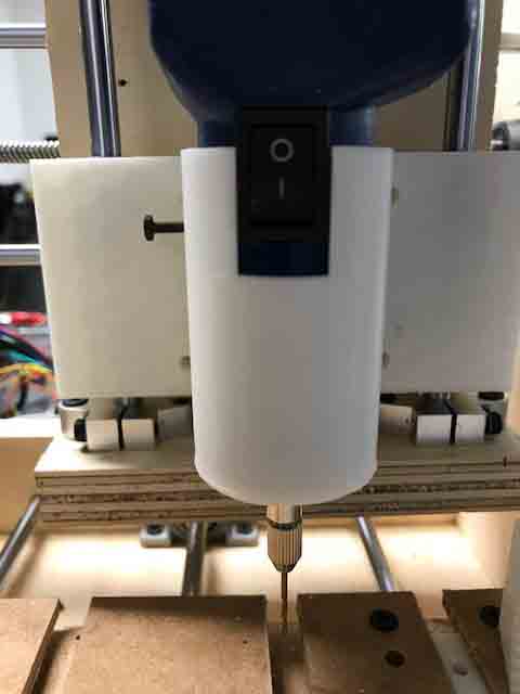
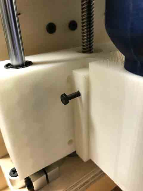
In this case, we used the multicam router for cutting the pieces. The folowing process shows how we made the Z-Axis.
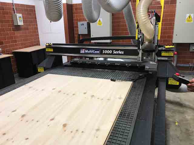
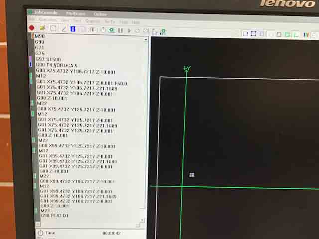
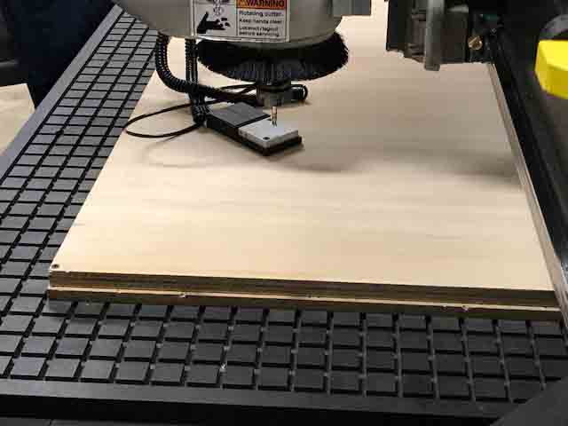
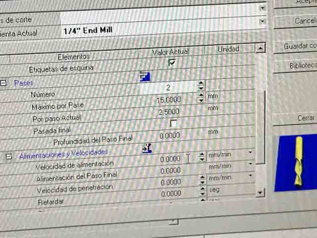
Fig 5. The set point, mill diameterl, number of passes, spindle speed.
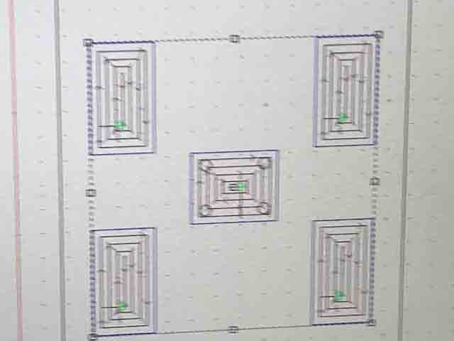
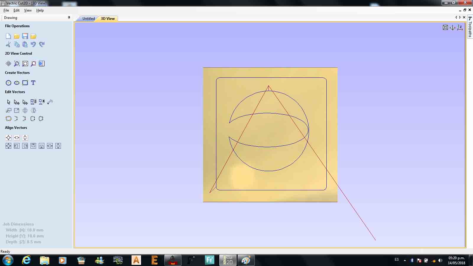
Fig 6. Toolpath simulation on the CAM software.
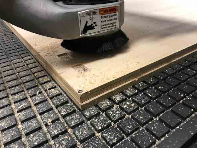
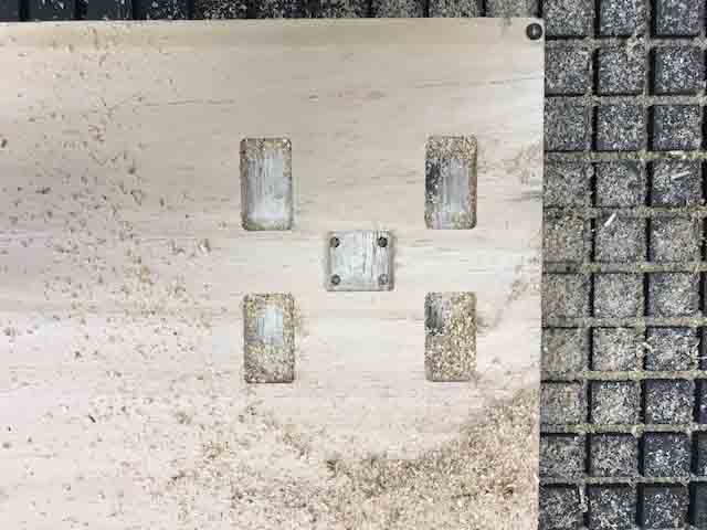
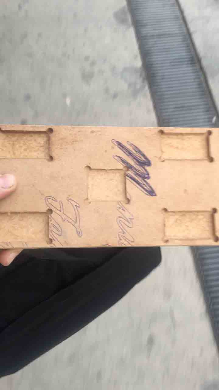
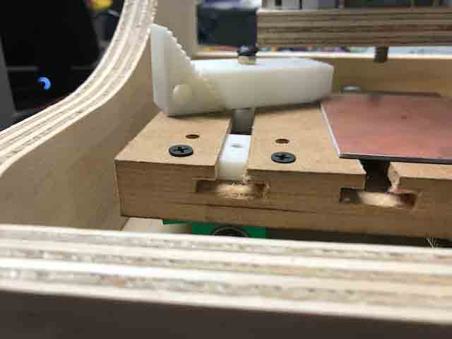
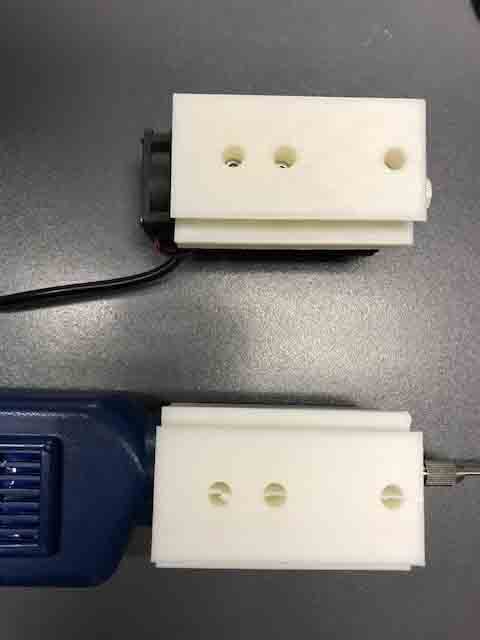
We made the bed for the Y – axis. The bed will support the material, whether it is for laser engraving or milling. The bed has grooves to hopld the material down.
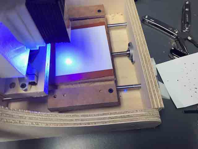
The advantage of this CNC consists of the interchangeable two – head tool.The first is a laser engraver and the second is an end mill.
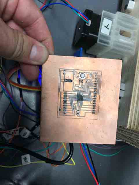
The documentation and firmware required so that the satshakit can read G-code can be found here:
https://blog.protoneer.co.nz/arduino-cnc-shield/
The documentation can be found here:
http://fabacademy.org/archives/2015/doc/projects/fabkit-0.4.htmlt
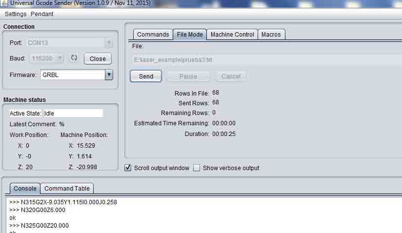
In this assigment we used GRBL to control the machine.
We used the command line to set the parameters for all 3 axes:
The stepper motor works with 1.8 degrres. Then calculate 360/1.8 =200. The driver has 16 mircosteps and the bolt has 1 rev 4mm. Thus the result: (200*16)/40= 800. This is the step/mm parameter for each of the axes. In the Universal sender code, in the command line wite $$ and then change in the universal sender code $100=800, which changes the X-axis , $101=800 change the Y-axis and $102=800 changes the Z-axis.
The documentation can be found here:
https://learn.sparkfun.com/tutorials/stepoko-powered-by-grbl-hookup-guide/software-machine-control-universal-g-code-sender
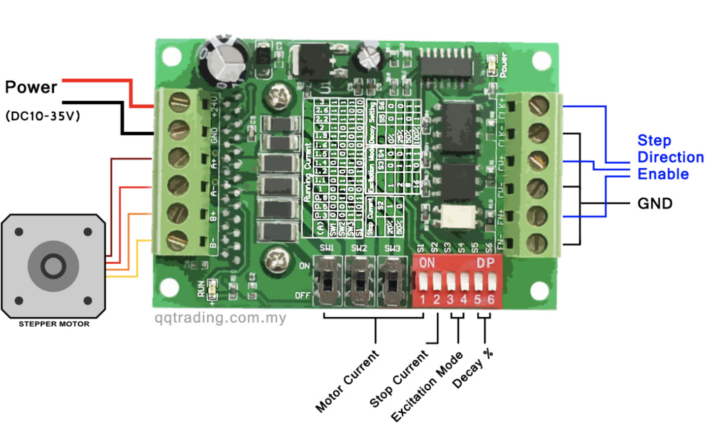
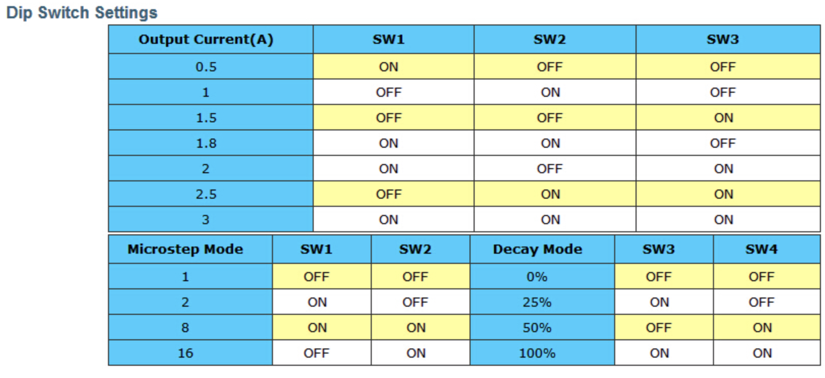
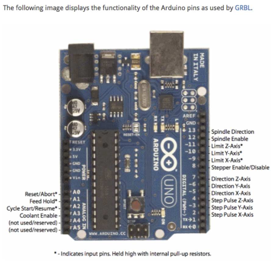
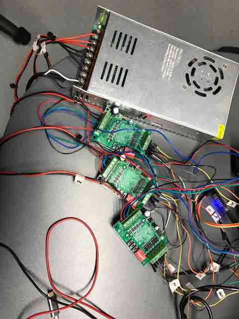
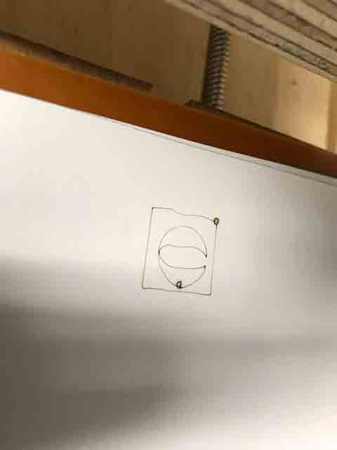
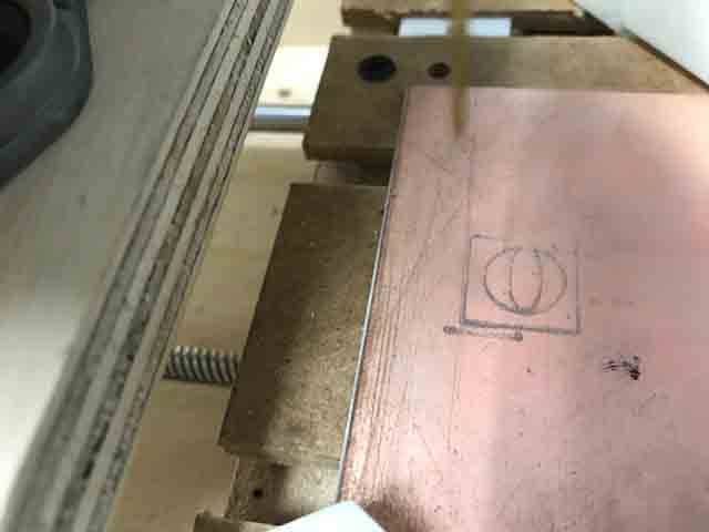
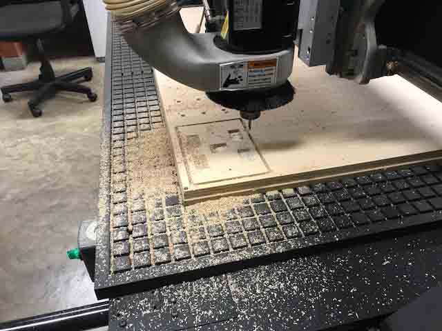
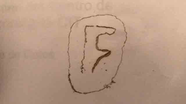
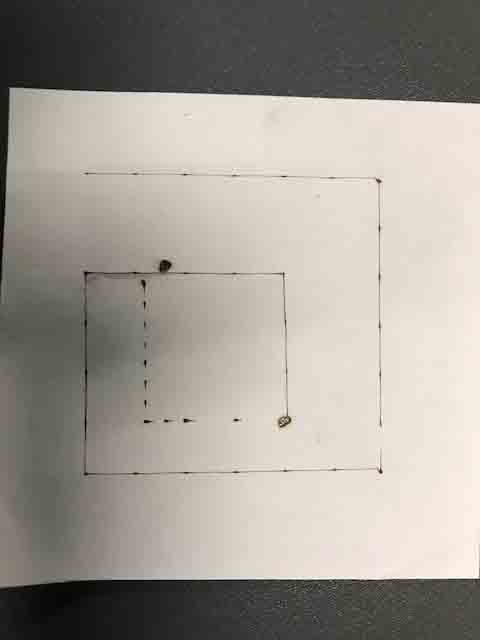
Fig 32. The final drawing with the CNC milling machine.
Videos
CNC Laser / CNC Milling Machine.
This video shows CNC laser.
Right mouse button to play video
This video shows Universal gcode sender.
Right mouse button to play video
This video shows CNC milling machine.
Right mouse button to play video
File example Gcode