I decided to make a Serial Bus for this week. In order to do so I had to make a bridge board and 2 or more node boards.
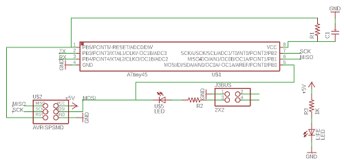
I started by designing the Node board.
First, the schematic.
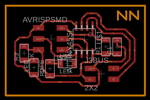
And the board.
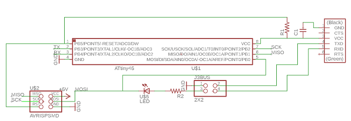
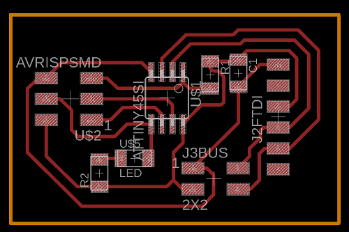
Followed by the Bridge board's schematic
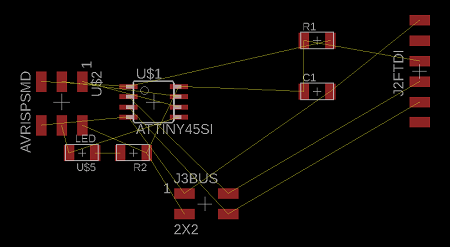
And the board.
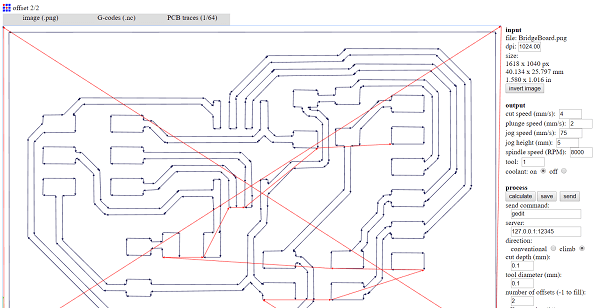
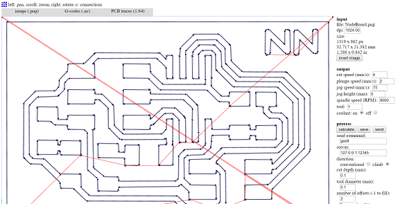
Next, I exported both monochrome png's and processed them for the G-codes on fab modules.
Bridge
Node
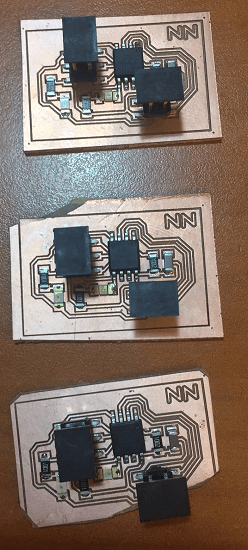
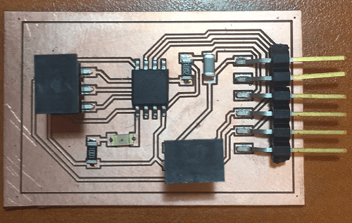
I sent both G-codes and cut 1 bridge board and 3 node boards just in case. Following I grabbed my flux and heat gun to solder my boards (Being truthful I finished them so fast I forgot to take pictures of the soldering process).
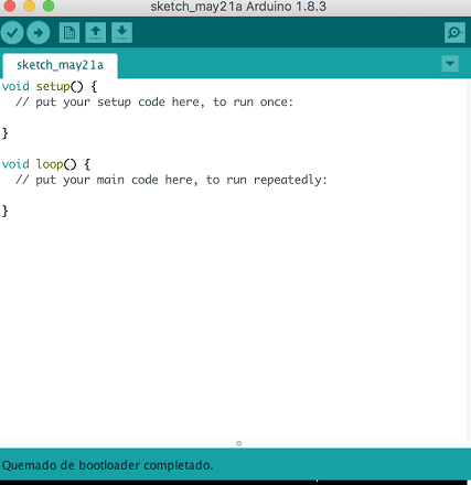
Next it was time to burn the bootloader on all boards. After going back to the dark ages of no compatibility I asked Fabricio for his Linux (it didnt work) so I gave it a shot with his Macbook and it worked for 2 Nodes and the bridge!
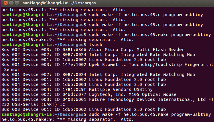
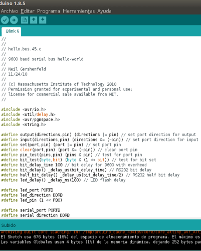
Bootloaders burnt I proceeded to upload Neil's code (Couldnt do it through a Linux terminal).
I managed through Arduino IDE version 1.8.5. First the Bridge so I didnt change anything to Neil's code.
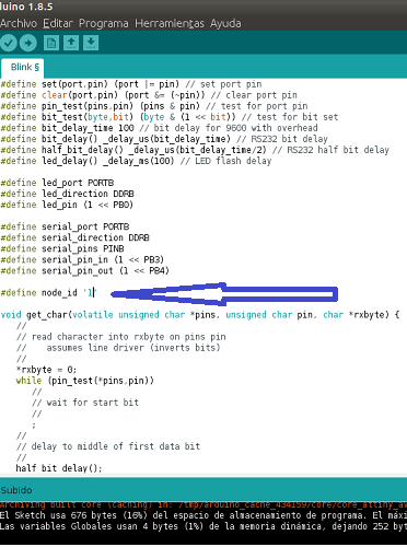
Next came Node 1.
I had to change the #define node_id to "1" (as shown on the picture below) so that the node would be recognized as a different board than the bridge.
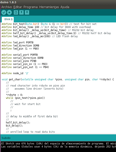
Finally, Node 2.
I had to change the #define node_id to "2" (as shown in the picture below) so that the node would be recognized as a different board than the bridge and node 1.
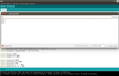
And I verified it was working with Arduino IDE's Serial Monitor while implementing it as shown in the video.
Download the original files from the links below:
NodeBoard Schematic: Eagle (.sch file)
NodeBoard Board: Eagle (.brd file)
BridgeBoard Schematic: Eagle (.sch file)
BridgeBoard Board: Eagle (.brd file)
BridgeBoard G-Codes: FabModules (.nc file)
NodeBoard G-Codes: FabModules (.nc file)