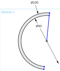
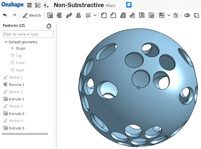
For this task I decided to use Onshape as I had done in week 3 and designed an empty sphere with different hole patterns all around. I started by sketching 2 concentric circles 90mm and 100mm in diameter, then I drew a line across the middle and trimmed everything but the difference between the 2 semicircles.
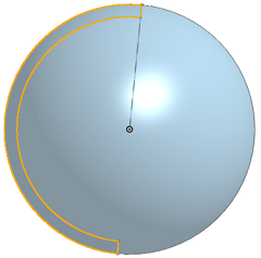
After I used the revolve function to generate a sphere.
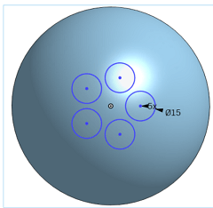
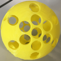
Then I cutted (extrude) circles of 15mm in diameter through different sides of the sphere using linear, circular and transform patterns.
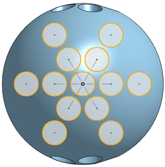
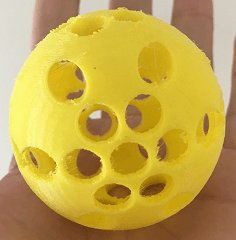
This was my finished solid.
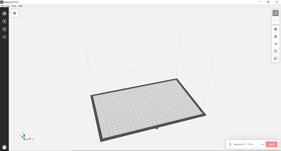
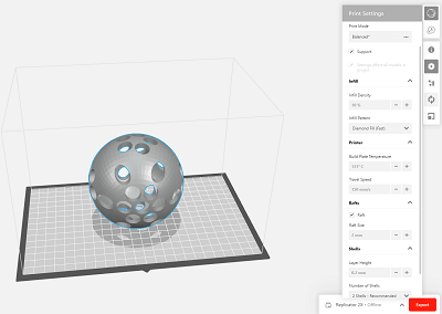
Now it was time to print my solid. First I selected Makerbot Print(3D printing software for Makerbot printers) as my 3D printing software (since I was gonna use a Makerbot it was the best option). The initial window looked like this
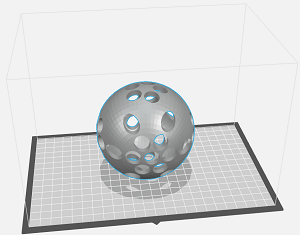
Next, I inserted my STL file.(File>Insert File..)
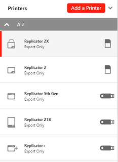
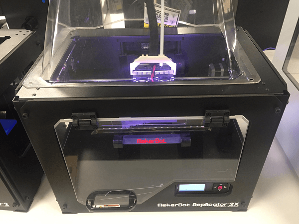
Following, I selected the printer I was going to use (Makerbot 2X).
Finally, I selected the printer's settings:
-Infill Density = 10%
-Infill Pattern = Diamond Fill(Fast)
-Build Plate Temperature = 135 Degrees Celsius (The image shows 131, there was a problem with my software so I used the lab computer to export my file.)
-Travel Speed = 155mm/s
-Raft = Checked
-Raft Size = 2mm
-Layer Height = 0.2mm
-Number of Shells = 2
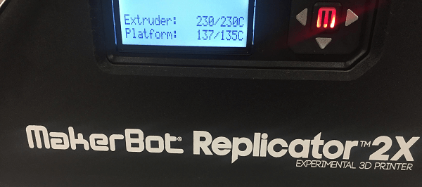
For some reason the newer version of Makerbot Print would only let me get as high as 132 degrees celsius for the Build Plate Temp so I had to use the lab's software(they conveniently kept the old version).
I proceeded to print.
And made sure the build plate reached 135 degrees (otherwise the printer fails, the material sticks to the extruder as it loses grip on the plate).
Originally I tried to save material by scaling my sphere into a smaller size leading to the error shown below(circles merged leaving bigger holes).
First Attempt:
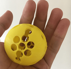
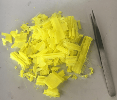
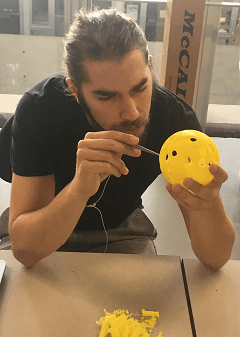
Through trying the 3D printers you learn that the error margins are tiny and still important, that there are limitations to 3D printing, when you abuse the support you have lots of extra work removing it once the object is printed.
This item could not be done substractively because the inside of the sphere is empty and the sphere has a thin thickness leaving substractive manufacturing no options.
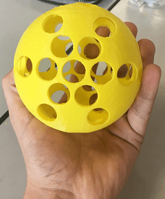
Second Attempt:
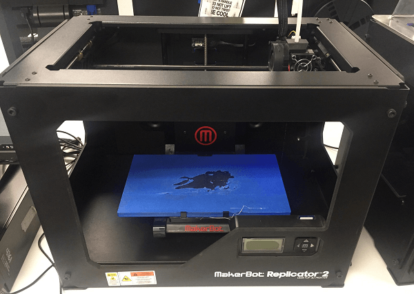
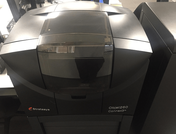
I have been 3D printing for about 3-4 years now and I've used: a Makerbot Replicator +, a Makerbot 2, a Makerbot 2X, a Stratasys and a 3D printer made in the lab I worked at.
Therefore I only used the Makerbot 2X for this week (also Stratasys printing material is expensive and we had just ran out of PLA filament for the Makerbot 2).
Here are the pictures of the other printers I've used in the lab throughout the years.
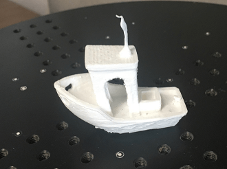
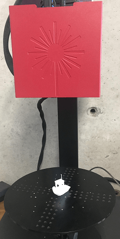
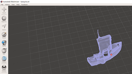
I had some experience with 3D scanning so this part of the assignment came easy. I selected an easy item to scan (red and black colors proved not to work with the scanner when one of the other students tried it). I chose a little white boat to scan as it had thin edges and a complex structure (3D printed with some errors) in order to understand some specific details about how the scanner works.
We use the GOM software in order to scan the solids.

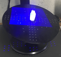
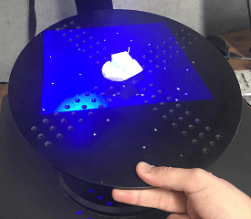
In order to scan an object with the GOM scanner we have in the lab you have to set it up in the center of the dish. You have to take pictures as you manually change its position and angle (by re-adjusting the dish) so the scanner gets multiple sides of the object and with the light refraction algorythms using the stickers as its fixed points to avoid losing track of where the object is supposed to be and doing so it generates the 3D solid on the screen.
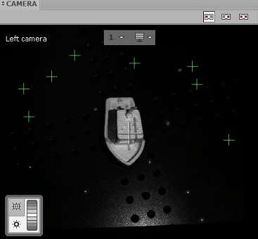
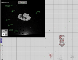
As you get pictures the solid forms on the screen.
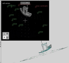
As you take more pictures you can see how the object gains mass and detail. Once you have your full object or something close to it, its time to export the file.
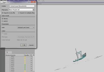
Its important to make sure the object will stay in its position since it has to remain there until the whole solid has been formed in the software, if it falls you have to start again.
Once you have an almost full solid you can store your STL. file and import it into Autodesk's Meshmixer.

This was my first time using Meshmixer so I only selected the "Make Solid" option.
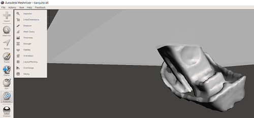
This is how it looked after.
For our group assignment we decided to use the Makerbot Replicator + (aside form abs being a hard plastic it was also the most abundant so...). We printed the files from the "Constraints" link in the Archive. You can download it from this link(which is where the link sent us) Thingyverse. Below is an image of the printed objects fitted together.
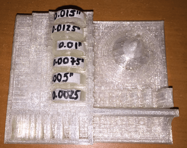
We discovered that the tolerance for our 3D Printer is 0.01 inches as any smaller tolerance wouldn't let the pieces fit and a greater tolerance meant they fitted loosely.
Knowing a printer's tolerance is extremely useful as it lets you know insight about how your objects will come out before you print them saving you time and money, and letting you adjust your designs accordingly.
Download the original files from the links below:
Additive Manufacturing Sphere Design: Onshape (.iges file)
(Heavy File so I linked the download through my drive 19mb)Boat Scan: GOM Scan + Meshmixer (.stl file)