For this week I started by thinking about making a trashcan for my uni's lab with separation for the different materials because they want to recycle and dont have much space for several bins.
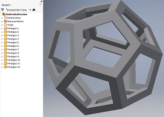
While brainstorming I took a little trip to the jungle to visit a nature lodge in the middle of the amazon rainforest and found a structure similar to my dodecahedron(week4).
When I saw this structure I instantly changed my mind and decided to make my dodecahedron into a lamp 5 times bigger in size with 3 legs that fit in the base.
I quickly generated a 3D image of what it could look like using inventor.
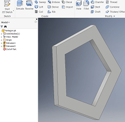
Following this I designed the 3 parts needed to make my lamp using Fusion.
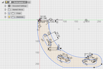
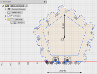
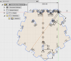
Once I had the designs I exported the 2D sketches in .dxf files so I could use them in the Shopbots software.
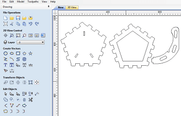
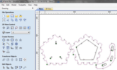
The .dxf files where to be uploaded to V Carve, the software our Shopbot router uses.
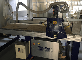
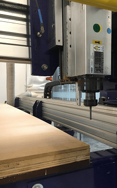
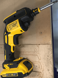
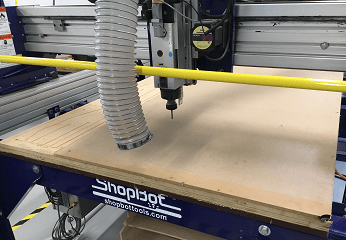
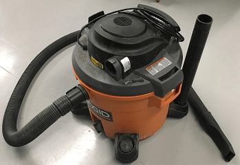
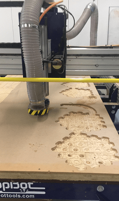
This is the router I used.
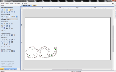
I found out V Carve tells the router to cut all lines in the .dxf (including the construction lines) so I had to re-sketch my design to avoid double lines(which prevent you from joining the sketch in V Carve).
Before we start the cutting theres a few steps to follow.
1st:
Select the material you'll be cutting(I selected 9.5mm MDF).
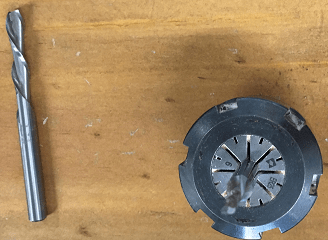
2nd:
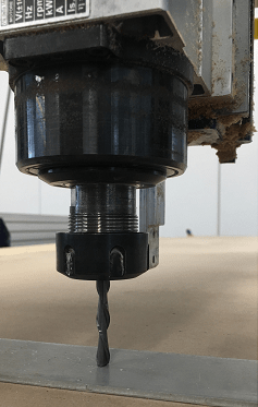
Select the tool you'll be cutting with(I used a 1/4 inch as shown below).
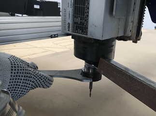
3rd:
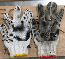
Change the tool (To do so you need long wrenches and gloves, we didn't have long wrenches so we got creative).
4th:
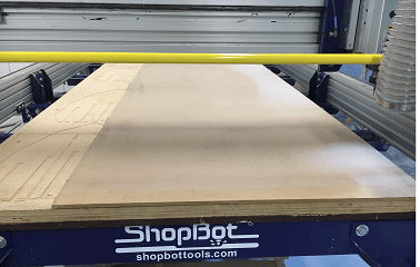
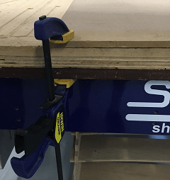
Set the plank on the router and adjust it using clamps.
5th:
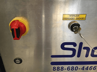
Turn the router on.
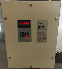
6th:
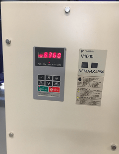
Make sure the rpm speed is the selected one(we chose 12000rpm, after a couple commands it changed from 8360 to 12000 as shown below).
7th:
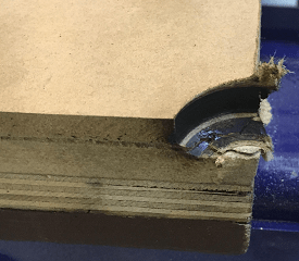
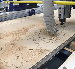
Set the zeros for X,Y and Z axis(We had some trouble setting the Z axis as someone had left the default width of the metal plate you use to set the Z zero to 80 mm instead of 2.7mm).
Needless to say this almost destroyed the router, but we were lucky and it only got the corner as shown below.
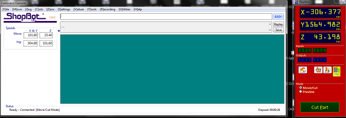
In order to set the zeros you can use the control or this software.
Before we set up our sketches we had to set the dimensions of the MDF plank in V Carve.
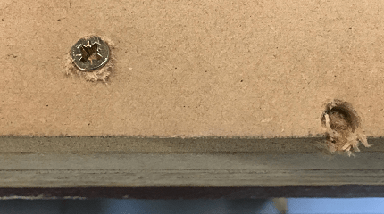
Once your sketches are the way you want them in "V Carve" you have to select dots where the router will drill the screws will hold the DMF plank once the clamps are removed(we use an electronic drill to screw in the screws).
For the drilling we considered to little margin on the first hole so we had to start over(as shown below).
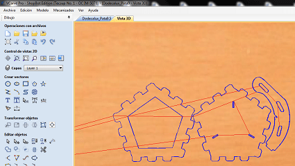
Next we need to select dots on the 2D shapes to prevent it from cutting all of it(this avoids the part from moving while its being cut).
We also need to pick the order the patterns will be cut in and what type of cutting will be done, this is done to prevent the object from moving.
(Example: If we cut the outside first, while cutting the inner pentagons errors would generate)
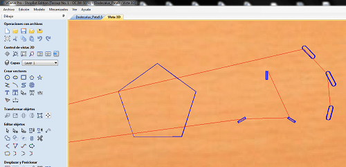
The order and cutting options I selected for my 3 different types of path were as follow:
1st - For the elipses inside the leg design I selected the option to cut everything inside the pattern.
2nd - For the inside pentagons I selected the option for the router to cut from the inside but only the border.
3rd - For the outer sides of the dodecahedron's faces I selected the option to cut the borders from the outside.
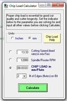
Last thing before cutting was calculating the chipload using the chipload calculator using the spindle speed we had(12000rpm) and the feed (800mm/min or 13.3333mm/second) which I got from the lab's staff .
As the router drills the holes for the screws you have to pause, drill the screws in and remove the clamps. Now we are ready to use the router properly. After exporting your file from V Carve and importing it into Shopbot you decide the depth of the cut and have a preview on the path the tool will take.
If you've followed all the steps then you can start your process.
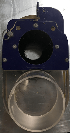
Usually the router has its own vacuum but the screws to attach it were missing so we used a manual vacuum.
Router's vacuum attatchment.
Manual Vacuum.
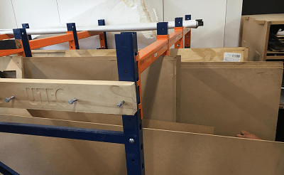
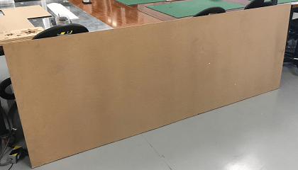
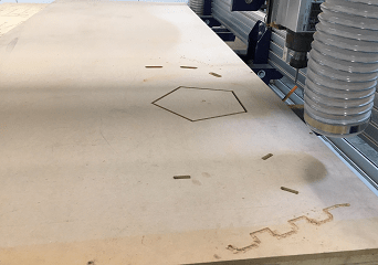
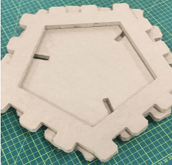
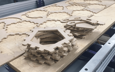
After about 20 minutes the pieces were cut, they looked like this.
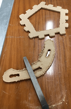
Lots of sanding to do in order to remove the extra material attached.
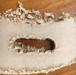
I discovered the leg design was a bit weak and the pentagons didn't fit so I re-designed the joints to make them fit and cut them again.
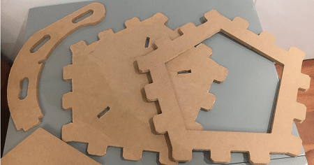
Now that I had some insight on the Shopbot I decided to send the whole design to cut on one go.
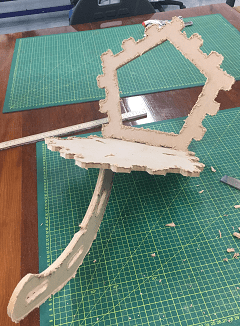
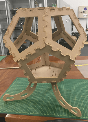
Finally, after lots of effort the Dlux's first standing prototype was finished.
Download the original files from the links below:
Pentagon: Inventor (.ipt file)
Dodecahedron: Inventor (.iam file)
Dlux Leg Design: Fusion 360 (.dxf file)
Dlux Side Design: Fusion 360 (.dxf file)
Dlux Base Design: Fusion 360 (.dxf file)