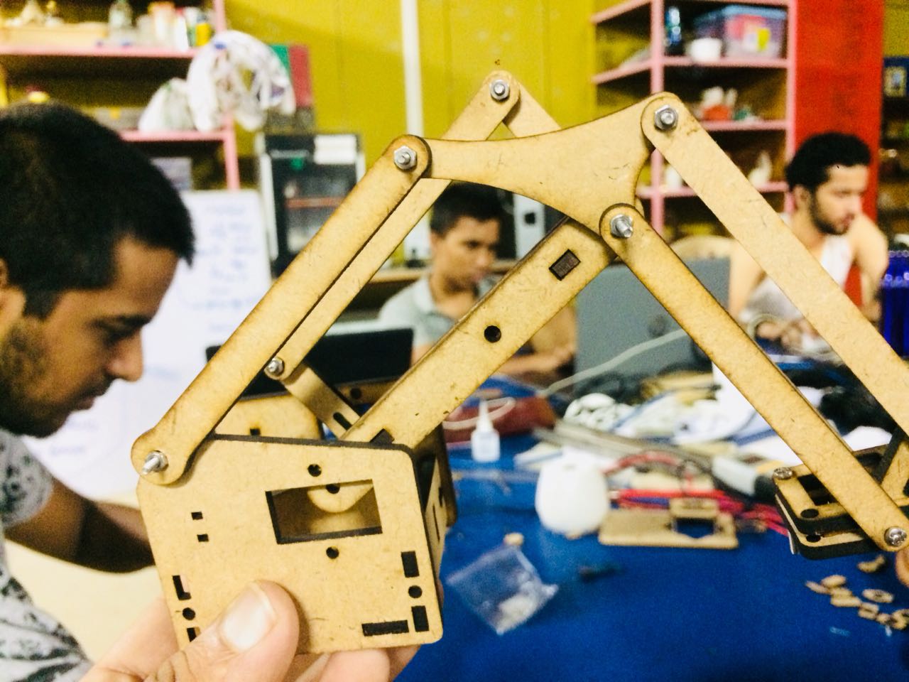
Hence we had two of our referance me arms that we had proposed to use and study for the linkage that we needed.
After a bit of brain storming we found that the four bar linkkage as seen here was one good to be used to solve our problems of using high torque motors.
Considering the same we altered our calculations and distributed the task amongst us again to develop the linkages, and manufacutre them
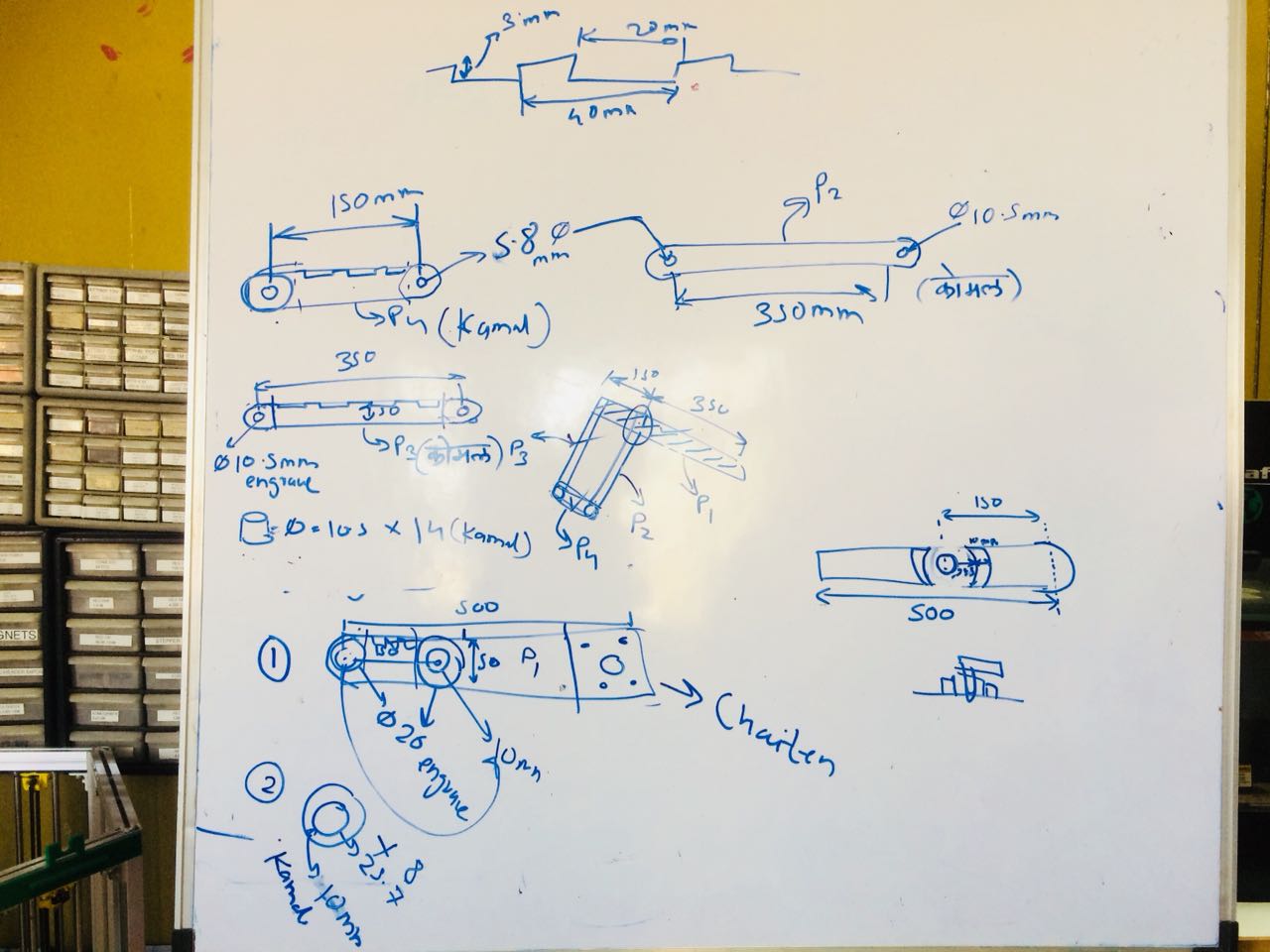
Hence now we had the schematics for the motion of the upper arm.
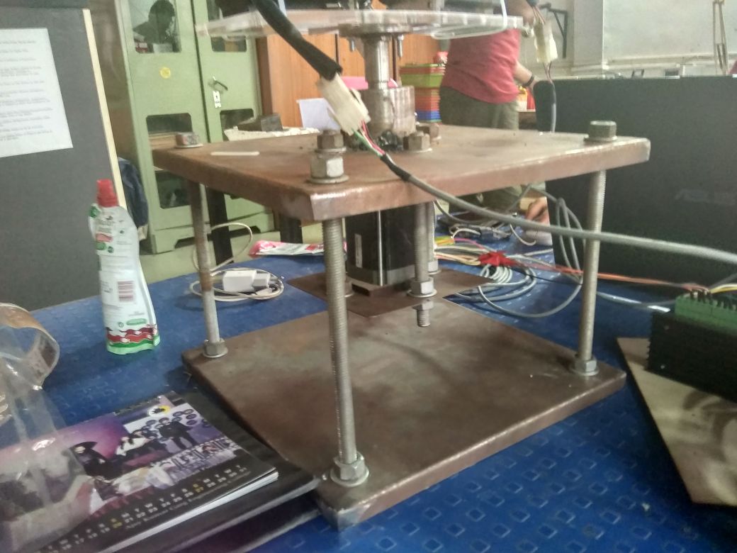
The next task was to make the mountinds of the motors on a base that was to be in motion.
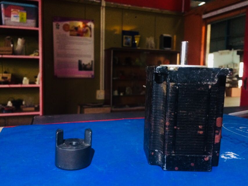
On top of this two motor mounts were planned such that the shafts of the motors would face each other inorder to maintain the parallel order of the linkages around the natural axis..
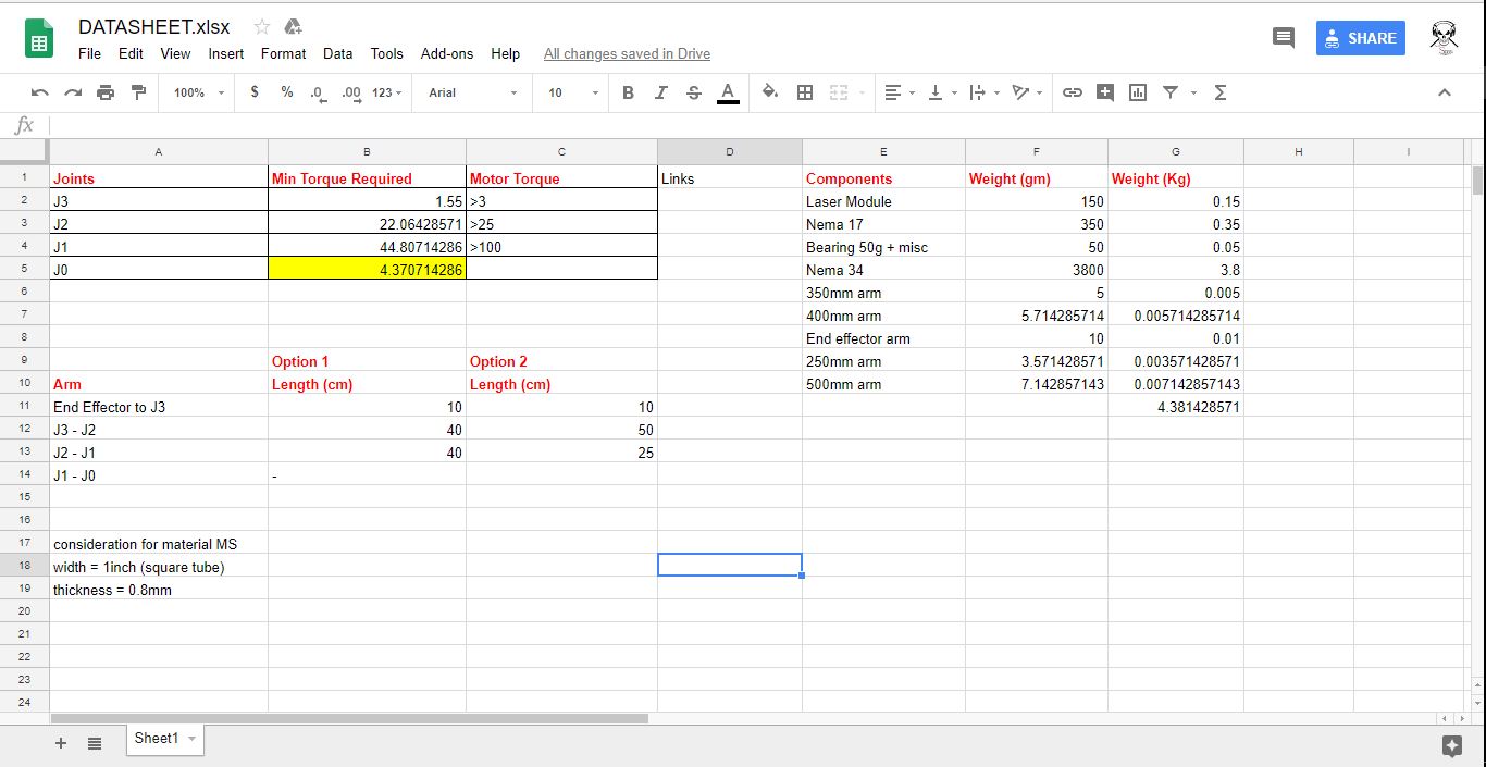
These mountings were planned to be pressfit initially for prototyping, considering the dimensions and other parameters, we came up with this plate as our base,
We mounted it directly on to the motor to test the motion
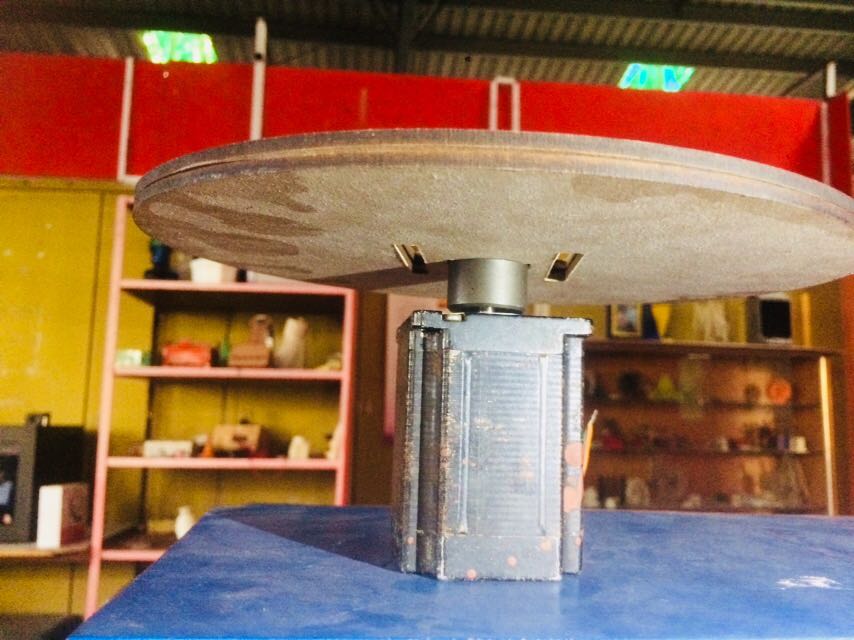
Also to test if the motor is capable of holding the max weight, we tried to get it into motion, using the same testing softwares..
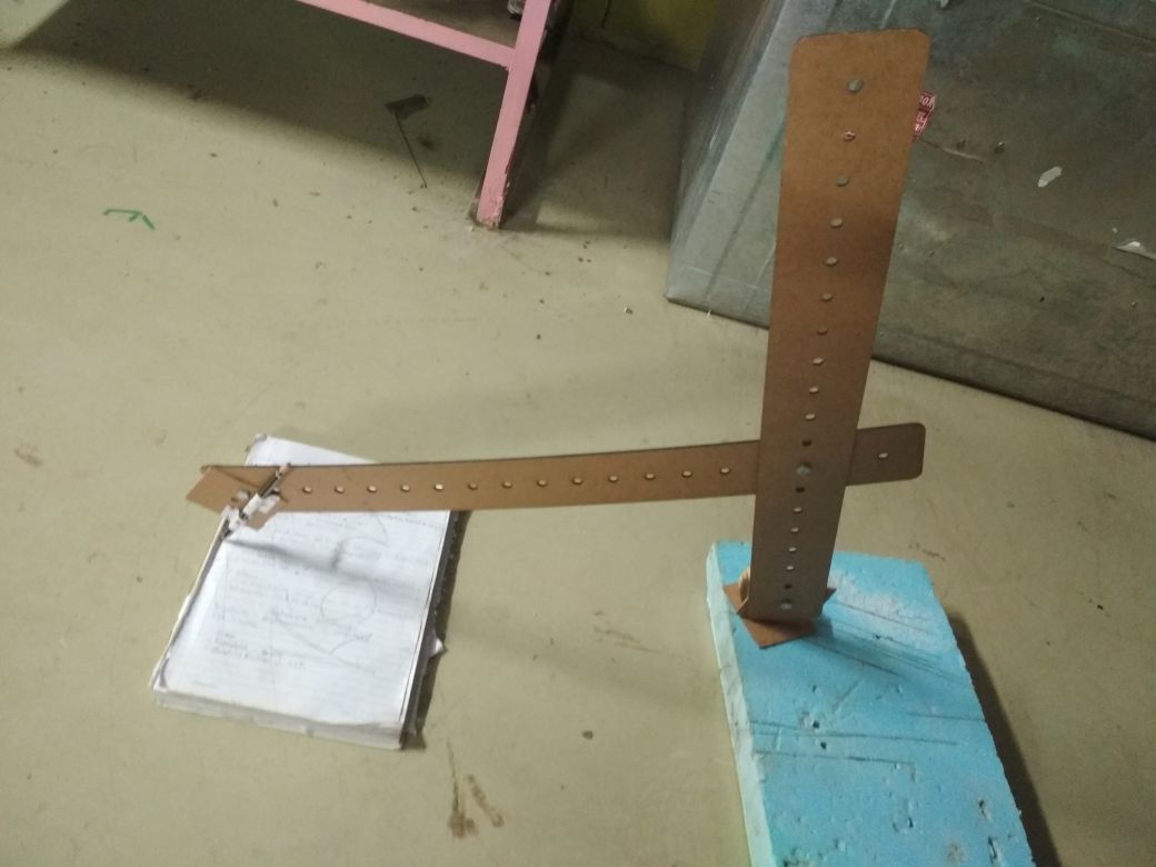
After this we realised that the direct mounting would have been risky as the load was going to increase, so we needed a perfect pedestal that could seperate the motor from it's shaft and.. hence we went with the manufacturing of the base with heavier materials inclusing MS and had achieved this as seen.....
For this there were two options for us to either attach a motor for the motion of the laser, that could addup to another degree of freedom, that would have added up to the interfacing of the effector too.
Or we had the option of adding a linkage mechanism that could pay us off to constantly keep the end effector parallel to the ground.
For the same we had initially went with adding the motor at the end effector, but we had problems in terms of interfacing the newly added motor, and also the weight added up at the end of the arm that subsequently added to the required torque by the base motor.
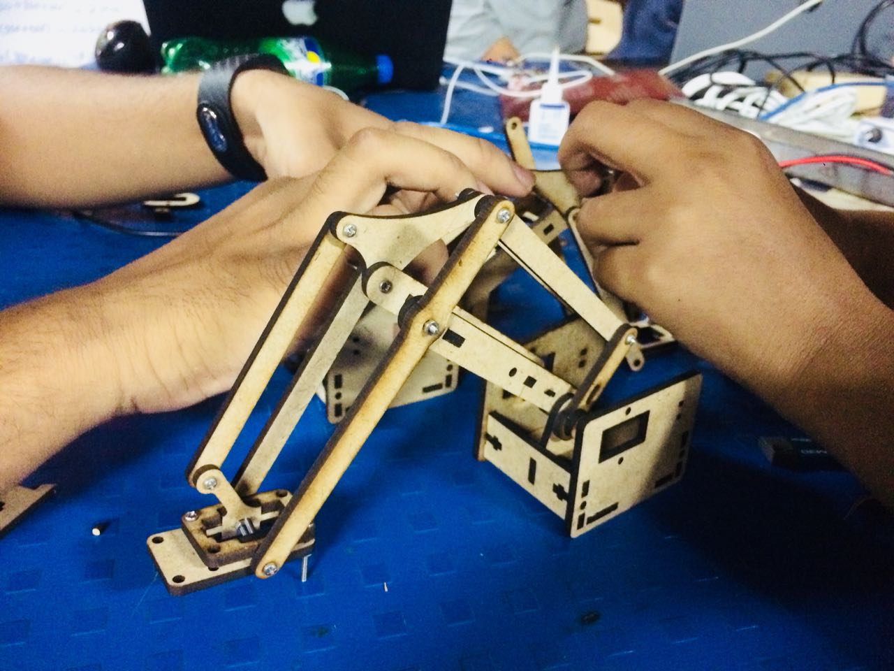
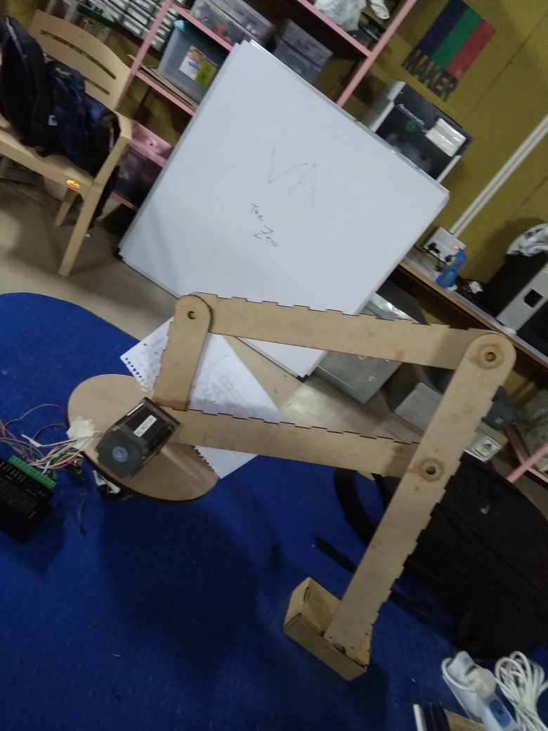
Hence we sat with the team to design the linkages this time we had do bot as our referance, where we studied the mechanism of do bot and got into studying the linkages.
After which we had the followinf basic strata in our hand (rohan's assembly)
After this we designed the individual parts for each of the members and got them printed, after which we had our arm looking as seen below.