Aim:
To understand the process of moulding and casting
Task 1:
Understanding the terms...
What is meant by casting?
The process of making a profile out of a given stock of material by melting and then forming into the desired shape is termed as casting.
The negative of the profile into which the molten material is poured is known as a mould..
What is meant by moulding?
The process of making the negative of the desired profile, in such a way that the desired part is obtained when the molten is poured into it.
For making a mould the basic criteria is to have a material having heigher melting point than the molten to be poured in it, so that the mould does not deform and there is a nearly precise profile obtained..
Process of making a mould.
There are various commertial and traditional methods of moulding which are listed below, with links for further information..
- Blow molding
- Compression molding
- Extrusion molding
- Injection molding
- Rotational molding
- Thermoforming
- Spin casting
Task 2:
Group Assignment
To understand the properties of the materials we use..
For this assignment we had a lot of material to test and play with, so we listed all of them and devided them amongst us to study the theorotical properties and then conducted the practical results together..
Hence following was the list and the details about all the materials we used..
- Silicon Rubber:-
This is basically an elastomer having silicon, carbon, hydrogen and oxygen in it's composition...
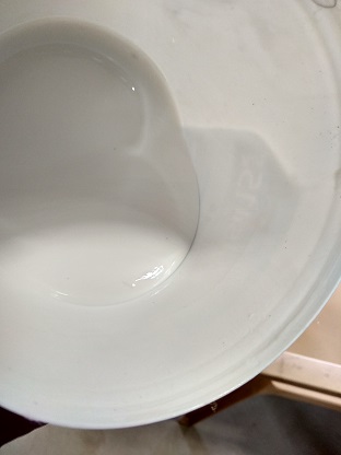
This intitially exsists in a liquid form at room temperature as seen here{The commercial silicon rubber that we had}.
Also since the material is purely formed by chemaical process, it has it's own safety measures, which if not followed may cause major damage..
Which can be found here.
For it to solidify it has to be mixed in a definite proportion with the hardner..
It supports a sustainance of a wide temperature range, rangeing from -50 degree C to 300+ degree celsius Form a soft elastic layer on hardening, which is quite difficult to further fabricate.. ..
..Properties we tested
For this we had decided to take the destructive tests for the material, before that we tested the effect of changing proportions of hardner and also effect of perfect and ill application into the mould.
For this we tried to cast the neagtives of our individual moulds with different proportions of hardner to obtain following results :-- Drilling a hole:-
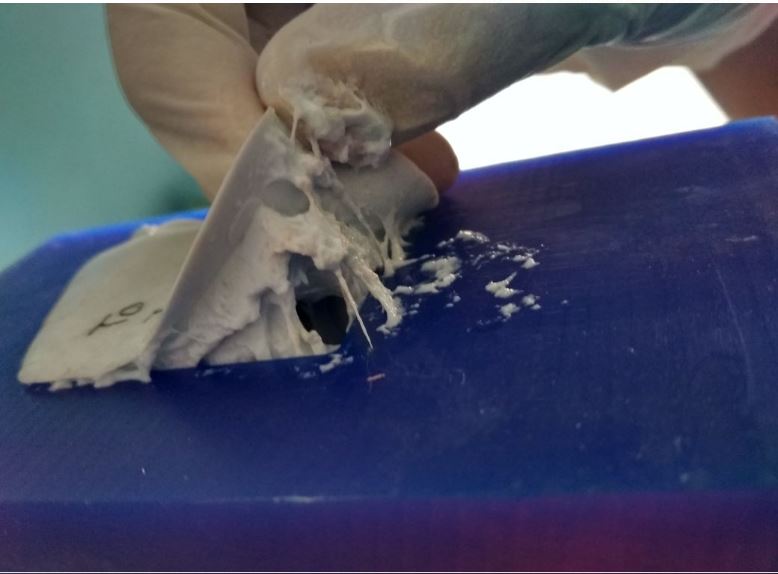
This test we had decided to consider to basically cross verify a comment by which the material is constantly addressed, "SELF HEALING", it's because the material has improved fatigue properties.
For this we didn't went to conduct the actual torsian-fatigue test rather what we did was to drill an hole through it.
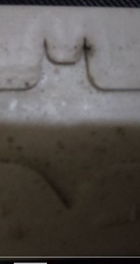
Initially we drilled a smaller hole (diameter ) where the polymer healed as see below
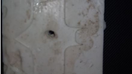
Then just to test the limits of the polymer we used a a drill bit of a bigger diameter of __mm and drill a hole through it. Out of which the material was actually deformed, we didn't get the hole of the exact size, it did shirk in size but we got a hole as seen here..
Hence we concluded that the material actually has an improved fatigue properties where it retains it's geometrical properties for most of the times. - Applying heat on the material:-
For this we wanted to actually see about how much temperature it actually can sustain without deforming, cause actually there was a lot of confusion regarding the temerature sustainance since the case is it actually also differs with the amout of hardner applied,
For this we had few different samples with differing concentration ratios of Hardner:Silicon , those being..
1:10
1:20
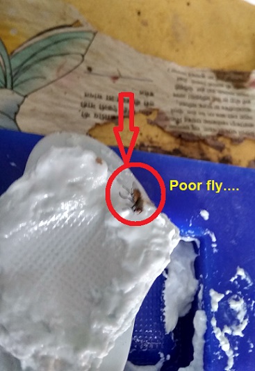
1:5 For this we just took a solder iron and tried to pierce at different temperatures to obtain following results:-
The expected was that at some point the silicon would start to burn, but the case was same here too, for all the three moulds, the solder just passed through the mould and there was no physical deformation as seen, above.
The next destructive test we decided was to directly by the process of contact heating..
So we kept it over the hot plate, the results were, it started to emmit vapours at 300 degree celcius, and turned brown
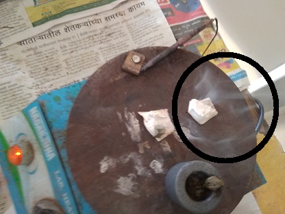
Hence we concluded that on constant and contact heat the silicon dosen't melt or deform but rather burns out..
Thus could be bit difficult when working with molten metals that would actually take more time to cure.. -
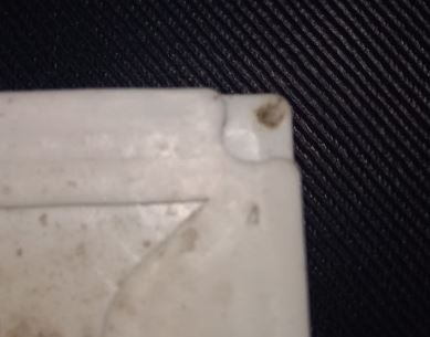
Effect of trapped bubbles:-
Basically even if you take the proportions of the silicon and hardner, there is a major issue if a lot of bubbles are trapped into the mould,
There was one of our mould which was not so carefully poured, there were lot of bubbles trapped into it,
The above picture is of the mould that was not cured due to large saturation of bubbles, Despite the propotrion being 1:10..
There was a sticky layer still seen as we removed the mould after 48 hrs
That was all that we had experimented and plotted our conslusions that helped us design and cast our moulds..
- Drilling a hole:-
This test we had decided to consider to basically cross verify a comment by which the material is constantly addressed, "SELF HEALING", it's because the material has improved fatigue properties.
- Machinable Wax:-
Basically it is a compound made out of high density wax, having a melting point of 116C.
Basically the high density of the wax block makes it viable for machining..
Further detailed information can be found here, along with it's technical and safety details. - Insta Mould:-
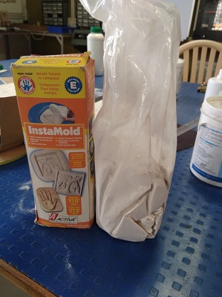
Insta-mould is basically a material equivalent to POP, which hardens with mixing with water.
Then only difference is, unlike POP you have to form the mould in a box and then press the figure(you want to replicate), into the mould.
Further detailed information can be found here, along with it's technical and safety details.
Task 3:
Moulding our designs
For this task we had to design a solid mould and then generate the same profile using the modella MDX20 milling machine.
For this I had used machinable wax as my raw material for milling the mould.
Before the procedure of designing let's come to a point about what is machinable wax?
Machinable wax is an extremely hard wax with a high melt point that has been formulated to deliver exceptional machining properties with high resolution detail.
Sub Task:-Actual process of designing
The process for designing the mould was nothing new, it was pretty same as making a cad design, but there was a catch.
For this assignment i wanted to cast materials that had to be heated and poured, for that I had to make a mould which would then be used for casting.
For this there were few considerations to be made in order to design it...
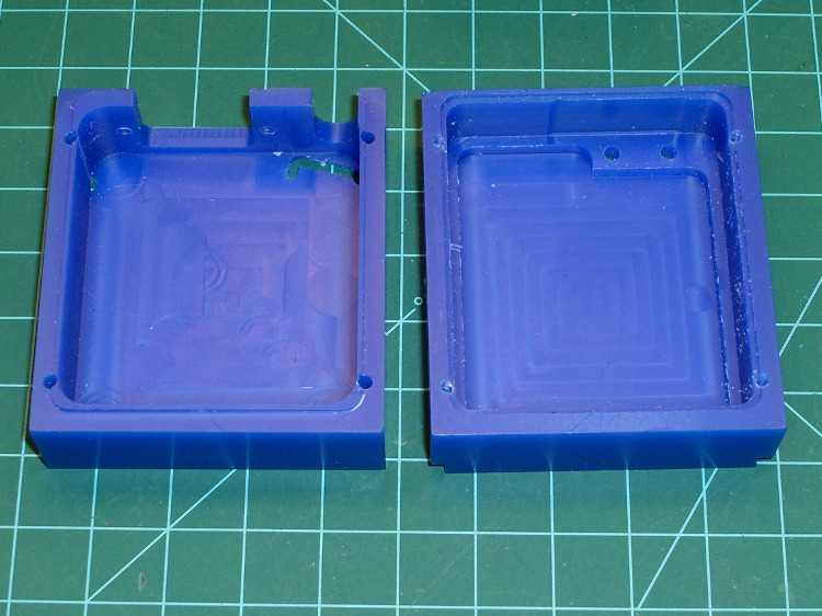
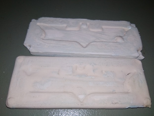
- The mould had to be designed refering the complete block of mould, and then creating the pockets into it as seen here..
- There had to be few spaces left for the fittings of the moulds, since i wanted to make two halves of the same muold to generate an entire object as seen in the mould above, so the process was to keep holes in one mould{Which would be extruded as bars}
and make extrusions in the other mould {which would make holes}
{NOTE:- Both the holes and their respective extrussions hace to be in the same allignment in order to be guided perfectly} - The next thing to be taken into consideration was the depth of the pocket witch respect to the flute of the end mill used.
The one which we used was having a flute of length 20mm, hence any edge deeper than that would have dashed the shank.
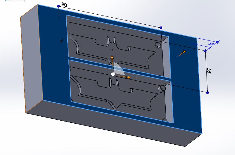
Also the other thing to be considered is the height of your object, this is because there has to be a certain space above the mould in order to give it the necessary strength and also avoid it from flowing when the heated material is poured.
Considering the above data I had kept a depth of 10mm where my object was of 2mm in height as seen..
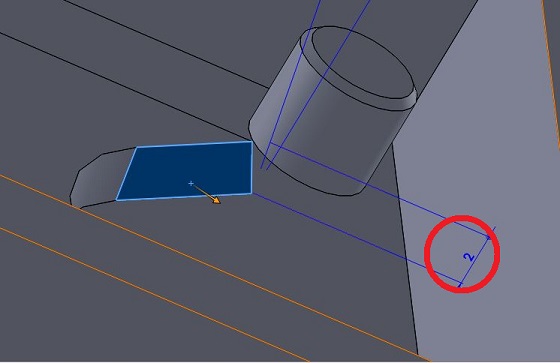
- Hence considering all the parameters I designed a mould that looked like this..
Sub Task:-Process of milling
The process was also quite similar to that of milling the PCB's, but there were a few glitches that I had faced which could be explained well in the structure below...
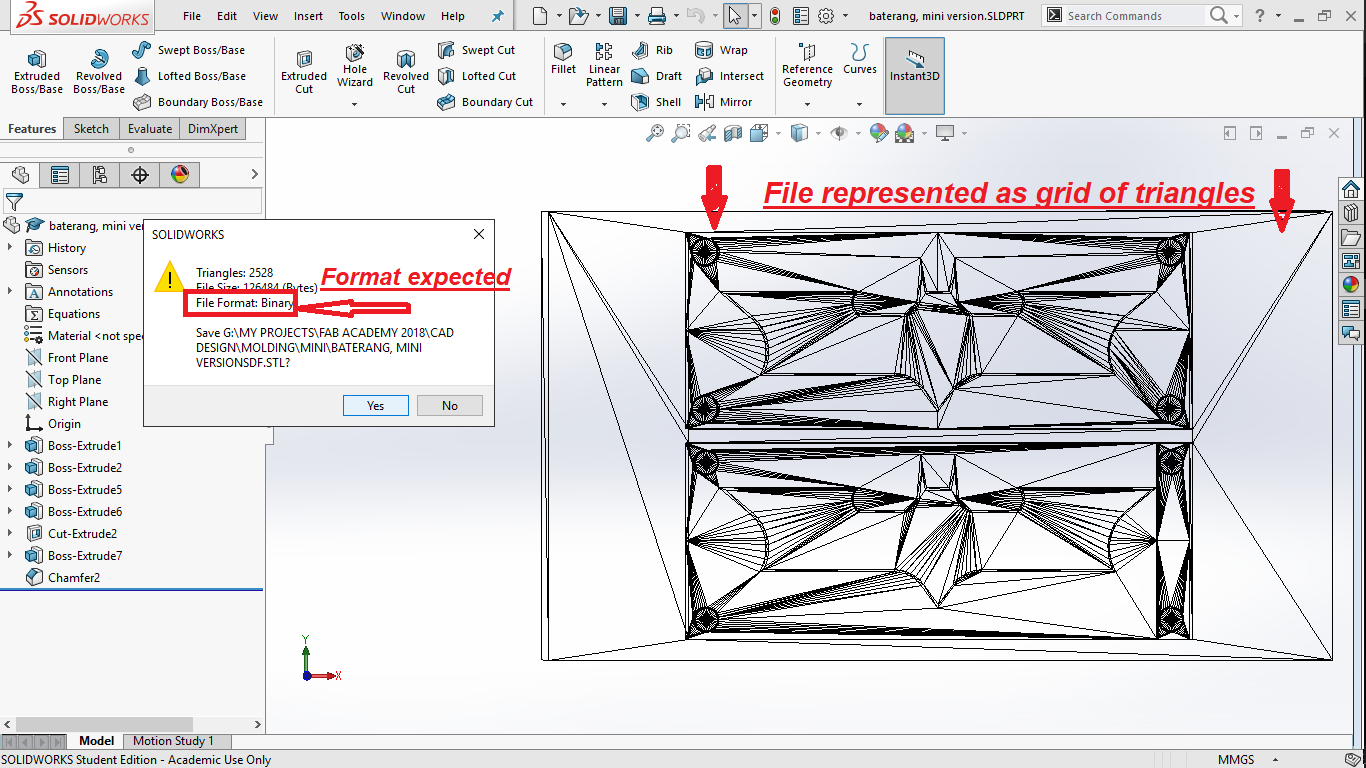
- First it starts from exporting your file in the format of *.stl, where the 3D model of yours, is converted into a format of an arrangement of triangles.
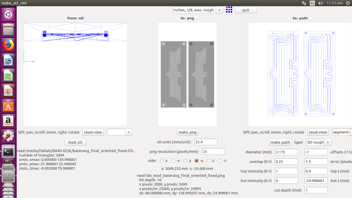
- Then you run the file into fab module, by selecting input as mesh file(*.stl) and output as *.rml,
and on the menu further you import your file, which mine looked like this initially..
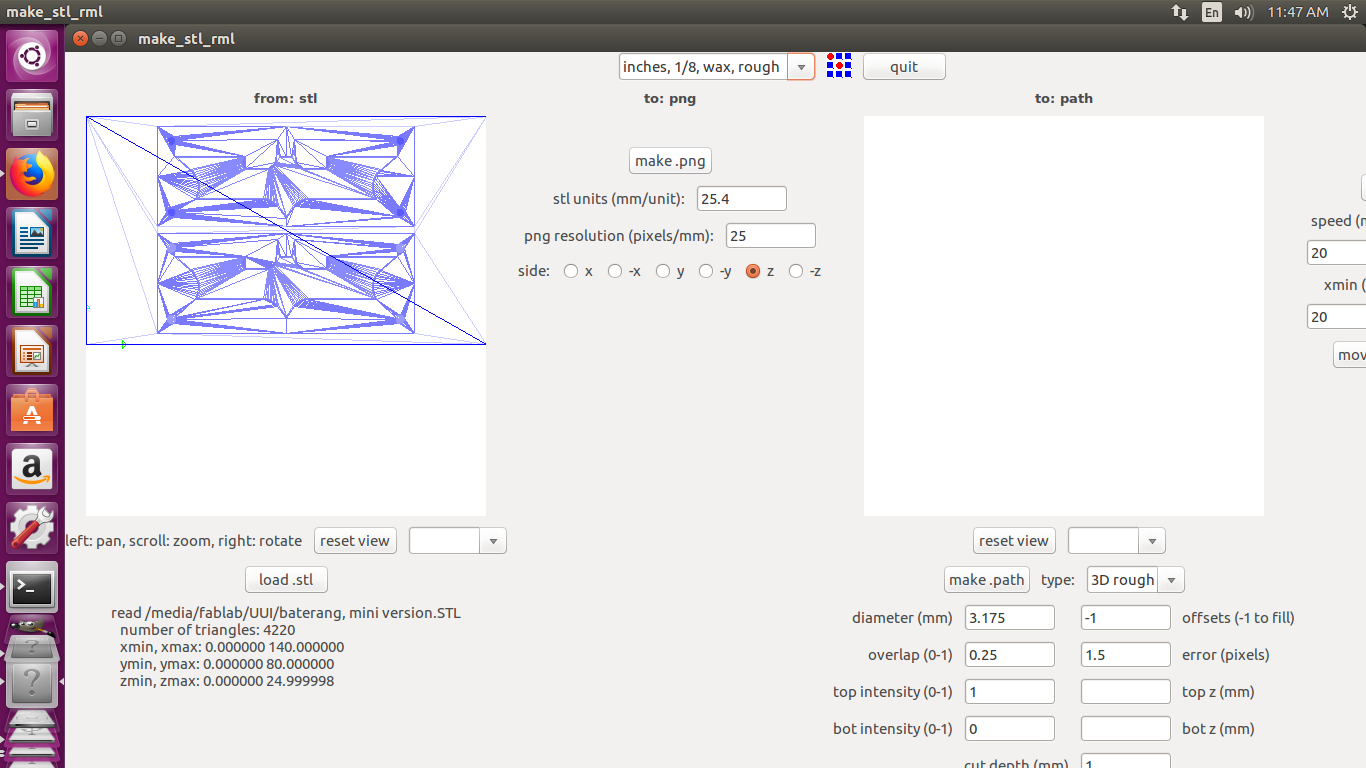
- Then you select an appropriate orrientation for your file and then hit make PNG, but in my case it was not showing anything for quite of a long time.
After a bit of search i found that there has to be a particular orientation of the *.stl file itself{i.e Perpendicular to the plane of the bed}.
For this I downloaded the autodesk MeshMixer, it allows you to change the orientation of your files as desired, the following GIF guides you through the process..
And then I exported the file as STL again and then tried to load it to the fab module, but it gave the similar error. - The next part I figured out was that the during the process of exporting the files into the STL format there are chances of the files to be broken.
That is there is a proper linkage missing in the the grid of the triangles which makes the fab module difficult to process.
Solution:-
For this I went to an online portal, NET FABwhich has a particular algorithm written which repairs the links between the triangles,

Here you just upload the STL file which it repairs for you and then you download it. - Hence I downloaded the file with that particular orientation and repair, and fed it to the fab module for which there was a PNG image successfully generated, for the -y selection of the plane
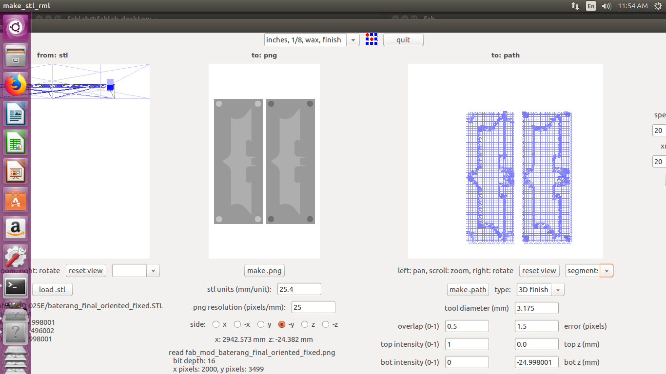
- Then then finally sent it off to make RML and mill
- {NOTE:- While milling wax with heigher depth cut, be sure to clear the wax after a certain point to avoid dragging of the bit into the wax to make impropper tracks..
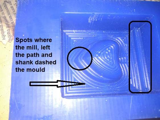
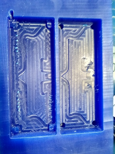
Hence after milling I had a clean mold as seen here...
Here I had only used the rough cut, cause i am still not sure about the issue but when I had loaded the machine for final cut it had left the origin for a particular reason and this was the first cut I had got, for which i decided not to risk the entire mould..
But anyways the quality of the rough cut was also satisfactory hence i decided to stick to that...
Task 4:
Casting
Silicon
Initially as planned i wanted to cast silicon rubber into the negative of the mould to generate the positive mould..
Thus following was the procedure I went into making a mould out of silicon:-
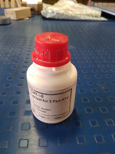
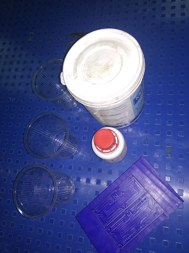
- Initial step was to gather the resources together, things i needed were as seen in the image
- Then the next step was to get the things into necessary proportion, for this the predefined proportion was a ratio of 1:2
hardner:silicon, respectively, but condidering the amount of hardner that was provided with the bottle of silicon had a proportion of 1:20 for the same.
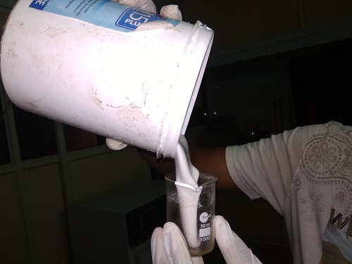
Hence i decided to stick to the middle grounds of using one mould with a proportion of 1:10 and other with 1:5... - The proportions I had to take were all in the terms of weight of both the items, but the case was i had all the measurements in terms of the volume, so instead of calculating and converting it to the required weightall the stuff i prefered to use a bit crude, but effective method.
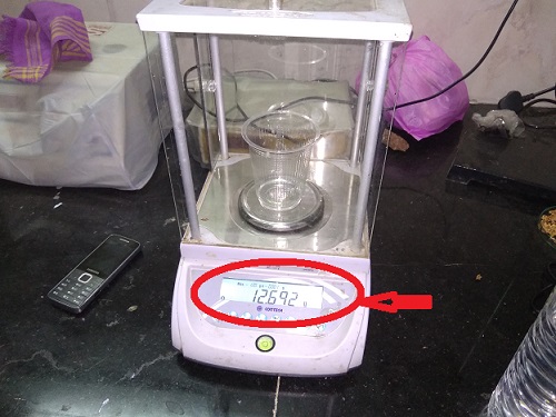
I calculated the volume of my mould, measured the required silicon in a beaker, and then weighed it to see the proportions needed.
- Once i did weigh the silicon i divided the weight by 5 and 10 respectively, to have an appropriate weight for the hardner
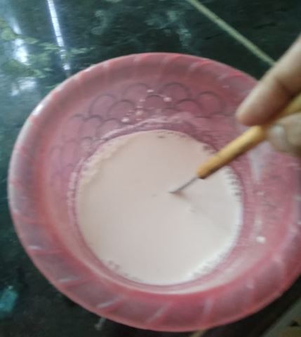
- Hence I had all the things ready in proportion and had to mix them up...
The only care ment to be taken here is that you need to stir it so that there are no air bubbles, and then the next thing is you don't waste much of time behind stiring it, it start to cure real soon..
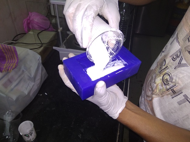
- Before pouring I did one more things, I had coated a layer of the mixture over the mould manually, this step I considered to ensure there are no bubbles around the actual mould
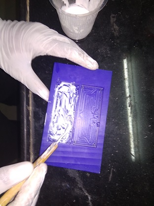
-
Then to ensure better perfection in terms of air bubbles, just move a sharp probe in and around your design, also it's preferd to plunge it once it in the holes where there is maximum chance of trapping the air.
This act is specifically prefered to do slowly to avoid generation of air pockets due to plunging.
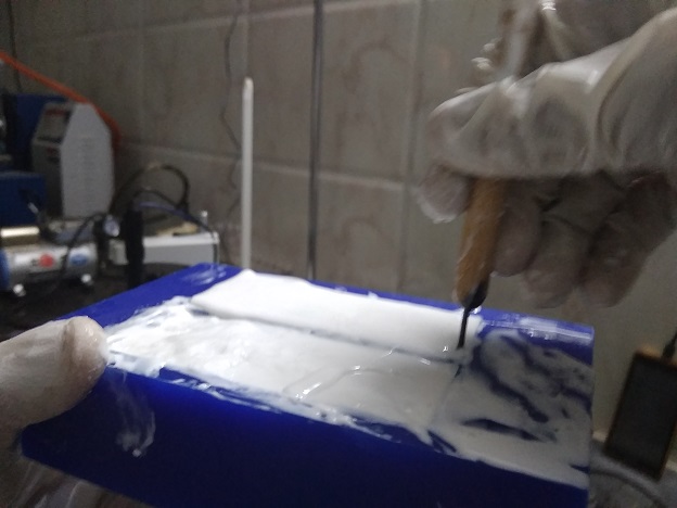
- And thats it you leave it to set for few hours{Time entirely depends upon ratio of silicon:hardner}, to finally get a mould looking like this..
Solder metal
It is basically a metal made as an alloy of tin-lead.
Has a melting point of aprosimately 300 degree celcius.
Hence I decided to go with it since silicon was properly able to sustain the temperature of the molten metal.
The process of melting was as follows:-
- Intially I had decided to go by joining both of the negatives and then pour the molten into it, but there the issue was the curing time and flowablity, basically the metal cures in a matter of seconds at room temperature.
- Hence the sating method I prefered was to cast in only half part of the mould, i.e only one negative side of it and then pour the metal into it and level it when hot itself
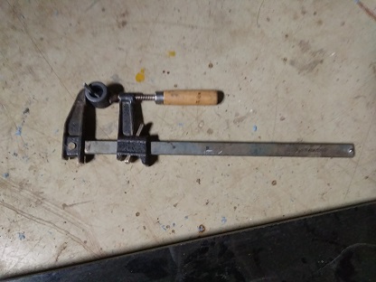
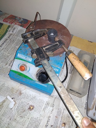
- For melting this initially i was unaware of the working of the muffle furnace that we had so I had made a clamp using a long C clamp to perfectly hold the crucible, then I had heated it over the hot plate in our lab
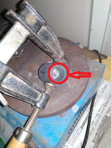
- After a few minutes I had got a molten that looked like this..
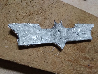
- After which I poured it into the mould and pressed it from the top. To obtain an intial figure as seen
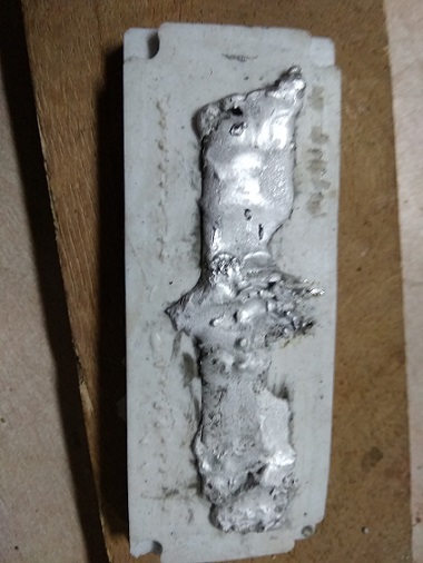
- This casted profile I had recieved...
Hydro-Stone
Hydro-stone is a powder basically consisting of:-
- Plaster of paris
- Portland Cement
- Titanium dioxide
- And impurities such as, Crystalline silica (Quartz)
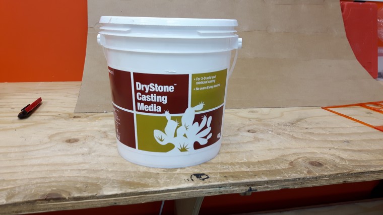
This material is basically very fine in nature and is extremely hazardous as explained here:-
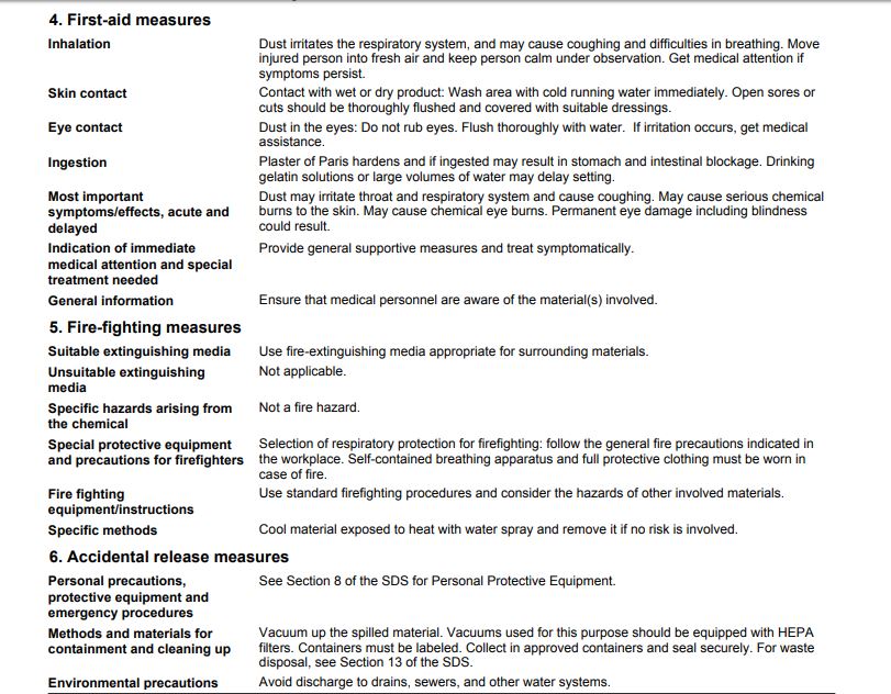
Hence a lot of care must be taken in dealing with it..
Anyways cutting down to the process of the moulding..
- For this material there are no specific ingredients except the powder and water.
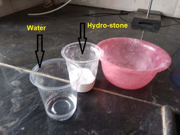
- The proportion of mixing water in hydrostone is 65gms of water for 100gms of hydrostone, i.e 65:100 respectively
- Hence I measured them seperately to mix them into a bowl, the care has to be taken that you don't mix it in much of a haste that might generate bubbles, also you mix it in a circular direction itself, and ensure all the blocks of the hydro stone are broken..
- Once done with the mixing part, the care that you need to take care when pouring is the stream should be fine as possible so as to avoid maximum number of bubbles,
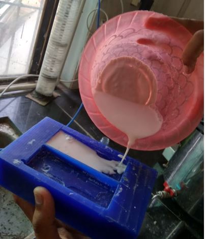
- Again here too, you can move a sharp tool arround the edges that could pop the bubbles up
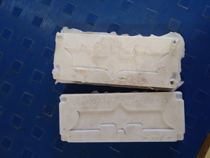
After the entire process I had got the following moulds as my output..
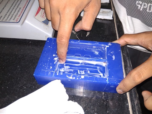
Problems Faced with Hydro-Stone
There were two problems that I had faced during the removal of hydro-stone casting, intially the mould was stuck inside the wax which had made it difficult to remove, this was due to lack of proper lubrication(mixture of oil+shampoo as suggested)
Hence I had no alternative other than breaking the casting down, it felt bad, but the satisfaction was about the finish the mould had achived due to absence of air bubbles.
So for the next part I improved my mistake and applied a solution of lubricant,
And I did set it to cure...
I was pretty unsure about what would happen once the mould was cured, and had kept a backup plan of heating and melting the wax to get the mould out.
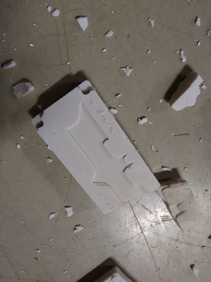
But for a matter of joke the mould actually dropped into my hand as i just gave it a jerk.What I had got, looked something like this..
The case now was that the finish of the mould was not that sharp as it was seen before in the debris.
This was probably because of the layer of the lubrication I addded, it didn't allow the particles to settle down perfectly and generated a la powder like layer.