Aim:
To understand the working of output devices
Basically this was assigned to test how do the boards that we designed function, to the commands that we feed them through..
For this we had to make a controller board and a driver board, which would function according to the instructions guided by the controller.
Task 1:
Points to be considered before designing the board for any output device.
Basically there are many essential considerations to be made before you actually design the board.
Some of them are listed below:-
- The first thing to be decided is basically the power consumption by the device that you use, because it is resposible for the track width that you choose and also the power regulating components that you might need, along with few other connection parameters to be taken into consideration.
- The track width of the tracs that are to be milled,
This does not matter much when you have a power supply upto 12V and current of 1A, but as they go on increasing the regulating components to protect the circuit and the track width matters upto a certain limit, to avoid damage to the components.. - The components for regulating the power supply, if dealing with AC or DC currents, or even in the conversion of them.
- The provision for removal of excess heat, produced by certain components, such as mosfets, to avoid the damage to the respective components and even the tracks.
- ANd few others like these play a very crucial role when you design output circuits
Considering all the above we can design a board for any output devices that we need, most of em could be found here..
Task 2:
Desiging of the controller board
This process I had actually thought to be considerably simpler refering to the processes I tried before,
Hence I started to design the schematic, starting with the things an IC would require to function, and then added the components, what I need for the out put.
For this task I had planned to develop the board for my final project because my project had a lot of output devices hence I had decided to test every port possible for it's working so that I could ensure maximum efficiency for my final project.
For this initally I had made one run through the board for final project without considering the assignment, that was the one consisting of many peripherals.
But later as I worked on the mechanical aspects, I was able to reduce the components and get the board into a significant format as the IC now I needed was attiny 44.
So I went to design the board and it actually didn't become difficult as I had a bit of experience of working with attiny 44
Hence following was the initial schematic that I had.
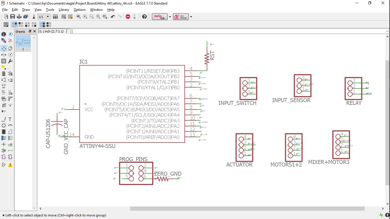
For which I had got the board auto routed without any much of difficulty
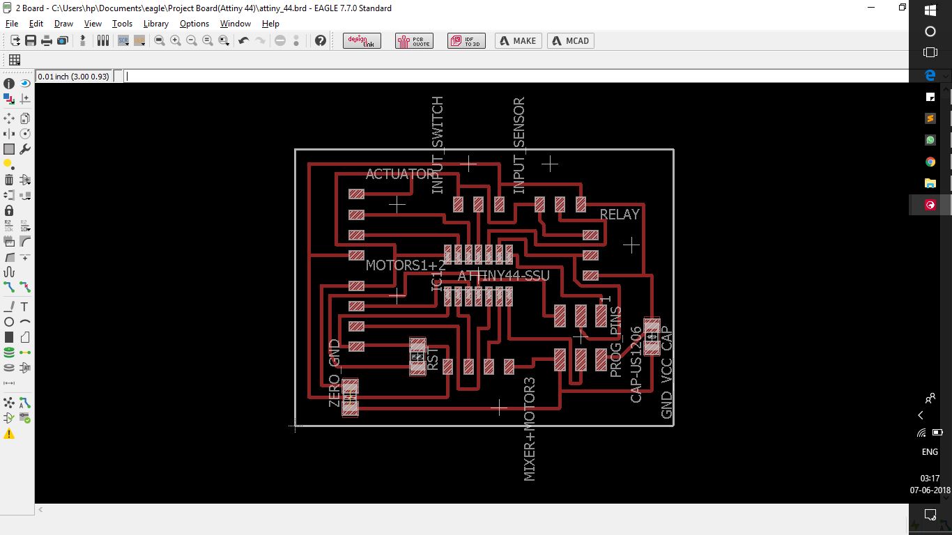
The crucial part here was the working of the board, since this was the same board I had planned to use for my project.
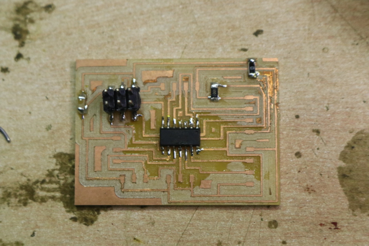
Considering all the parameters, I milled the controller and got it soldered carefully to avoid any mistake that could leave me into the trouble of debugging.
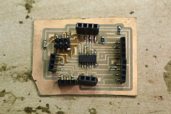
Once I was satisfied with the soldering of this board, I went to design the operator board.
Task 3:
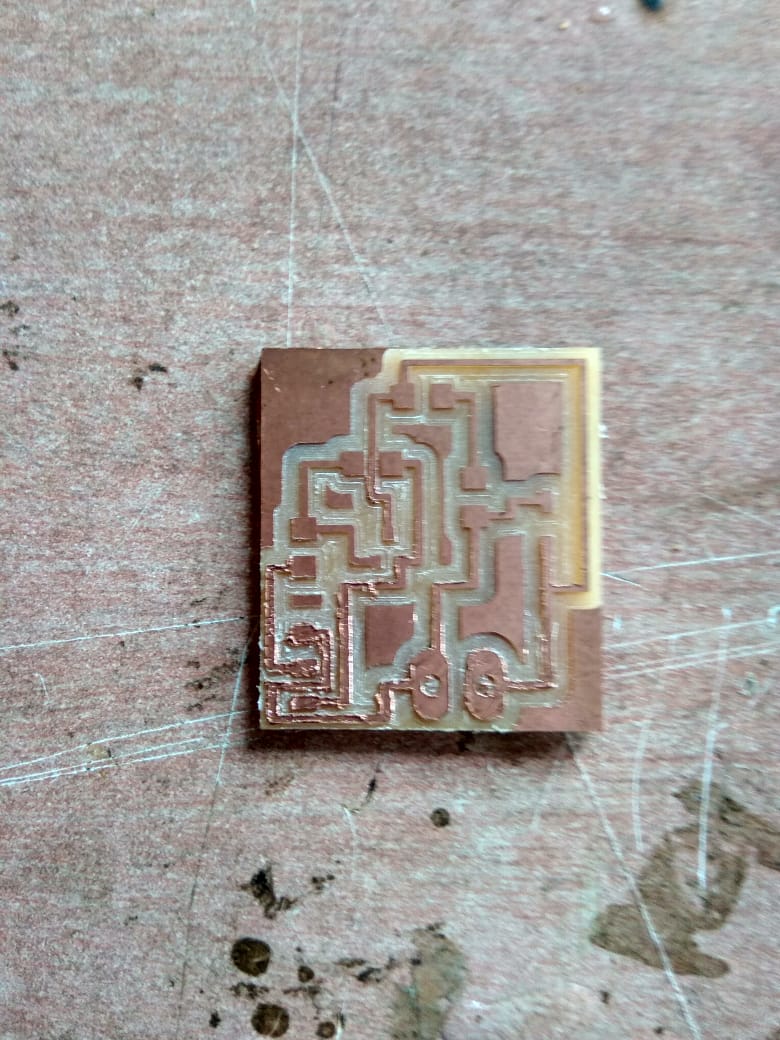
Desiging of the operator board
But fortunately it didn't trouble me as it was experienced before.
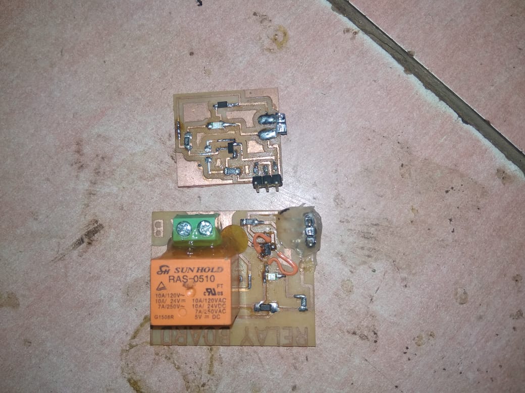
This was my controller board, now according to my need of mine and the assignment too, I had to design a board that would communicate between the controller and the output device.
For me I had few motors and a solenoid as my output device, for which I had planned to design a DC motor driver but since there were a lot of motors, and the unreliability on the custom designed products I decided to work with the standard products, and rather develop a relay circuit for the solenoid.
Before going into the design the question to be asked was, what is a relay and what are it's functions?
It is basically an electriaclly operated switch, that works on the principle of iduced magnetism due to the flow of current, i.e when current flows through the coil, one of the terminal of the relay becomes active and completes the desired circuit.
Similar was my requirement for the solenoid that it has to be turned on and off, on the command of a signal.
Underestanding which I got to design the relay circuit, I was initially skeptical about this since I didn't knew how would a relay circuit would be designed, I just knew with the functions of it.
But later I found this image which guided me through the dsigning procedures for the same.
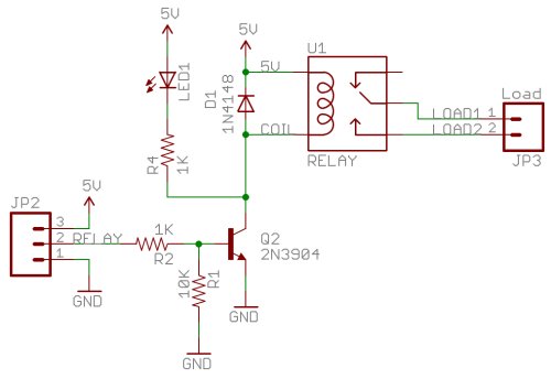
Understanding and refering which I had my schematic ready for the relay..
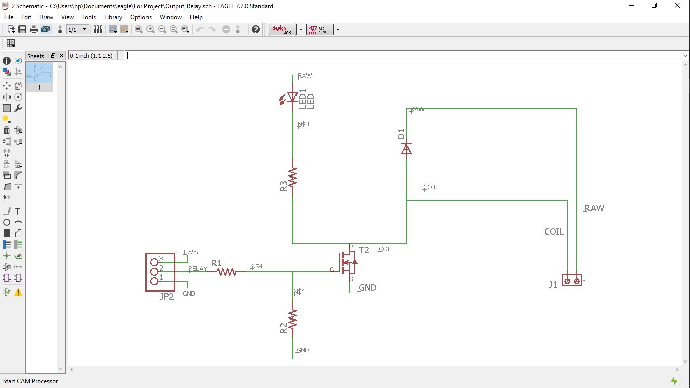
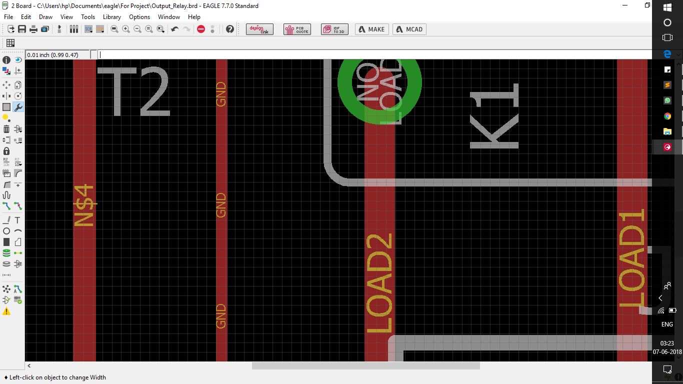
And following the same I routed the board..
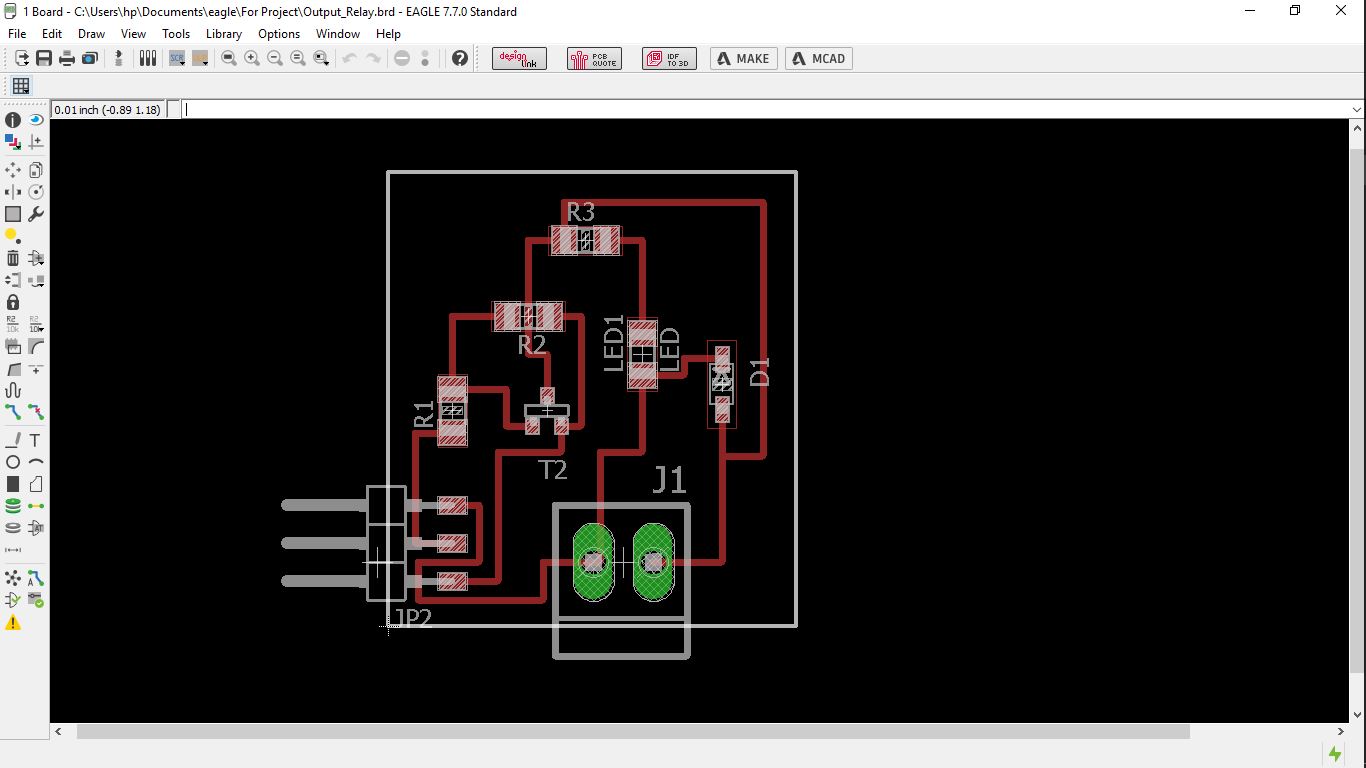
Here I kept the traces that go into the relay fatter in comparison with the others, considering the power that was to be transfered through those connections, although it was not so much, merely 12 volts, but I decided not to take risk aginst it.
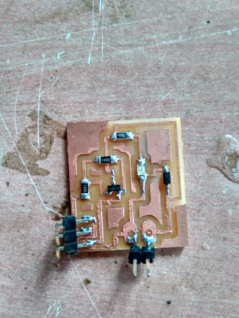
After this I had milled the board and soldered it to obtain the following kit.
Task 4:
Programming and testing the boards.
The programming of the board went pretty well, as the only thing I had to do was use the standard procedures of buring boot files, and then a program.
For this I had used the standard blink program that was found in the standard examples of the arduino.
The one which I had wrote for testing the operation of the relay was the actual one that I was going to need for the project, i.e to keep the relay on for a particular time, and then turn it off, but instead of testing it on a solenoid, I tested it on a motor to obtain visible results..
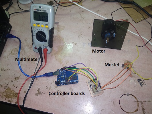
For the same I had a simple setup of a laptop connected to the Controller board, which was further attached to the operator board consisting of the relay module, which was further connected to the motor.
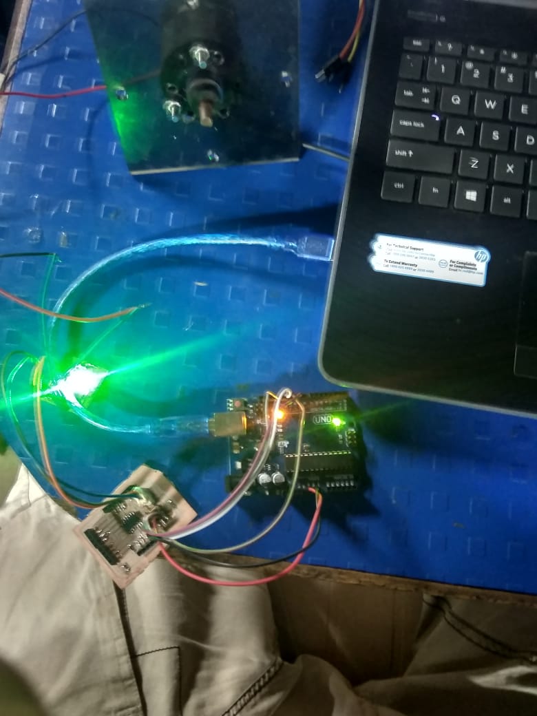
For which following was the simple program that I had loaded, it was basically the blink code, send just to test of the board, is workding and if the motor(simulator for relay), was working..
Refering which I had the desired results as seen here..
Task 5:
Group Assignment
The task that we had this week was to check the power cosumption of the devices that we used.
This is a very important factor when there is a need of optimisation in any point of the machine, the analysis of this gives you a detailed idea about the setup that you have and about the setup that you could optimise.
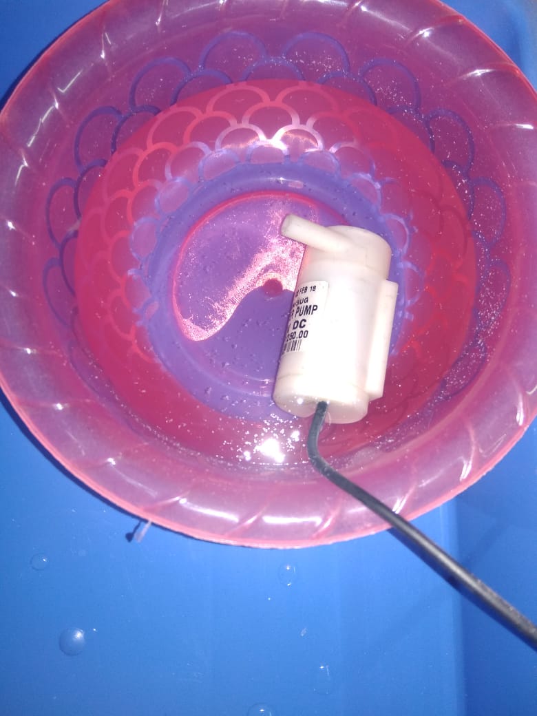
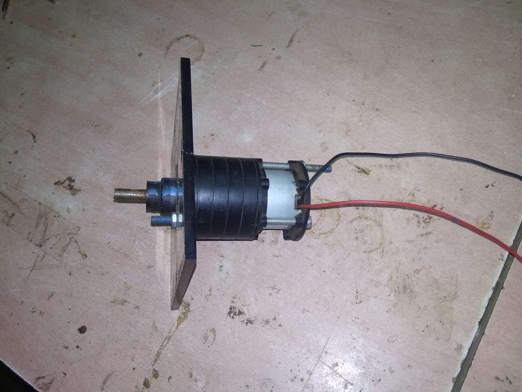
For this we had taken devices into consideration one being a 5V DC motor, and the other was a 12V DC water pump.
The operational setup was a processor board connected on one side through the arduino, an output device out of the ones stated above, directed through the relay.
For the operations we had two sets of relay, one being just guided by a mosfet cosidering the lower power ratings needed, and the other was one having physical relay cosidering the higher power ratings needed.
Sub Task:-Testing the power consumption for the motor.
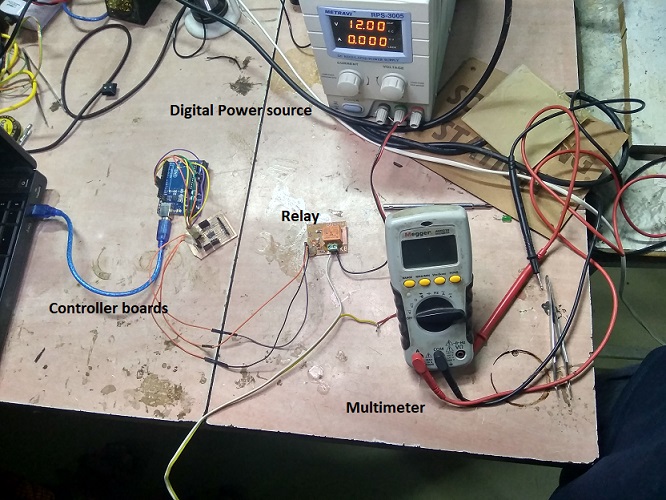
For this we had made a setup as seen in the image below, consisting of a 5V DC motor, a mosfet, controller board, arduino.
The code fed to the board was basic blink code with a delay of 5sec, that would give us significant time to anyalyse what was happening.
Hence we fed the code and got the setup working, that gave us following results, as seen in the video below.
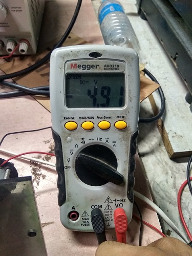
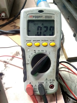
Also here both the parameter for the calculation of power ( voltage and current), were supposed to be calculated manually using a multimeter, which was once to be setup in series (for getting the current), once in parallel(to get the voltage)
With similar we got the following reading of voltage and current..
The next thing left was just to calculate the power consumption using a simple formula of P=VI, that explains as power = voltage * current.
Hence considering our reading our motor had a power consumption of 0.1423 Joules
Sub Task:-Testing the power consumption for the motor.
The next thing to work with was the water pump.
For this the setup that we had was a relay, operated by a controller board, an external power supply, and a 12V dc water pump.
The code that we were supposed to use was the same, which we burnt and got the circuit working as seen here.
Here fortunately the digital power supply was capable to directly show the readings of the voltage and current.
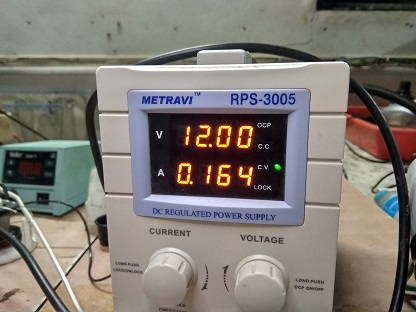
Hence after this the only task was to calculate the power consumption using the same formula as mentioned above.
Considering the same the power consumption of our water pump was 1.968 Joules