Aim:
To learn about cutting technologies, and make use of some
Task 1:
To learn about the laser engraving machines.
This task included in going through the details about every machine, and getting to know its abilities and all the possible tasks that can be pulled out on each of them.
The machines that we have at our facility are
1. The SIL laser engraver
2. The Epilog laser engraver
Group Assignment
For this task we had a group assignment where w had to study about the properties and kurf of the laser engravers, for that we splitted ourselves into two groups, each assigned with one machine, and we had to explain our tasks and conslusions to others.The conslusions of each assignment for insividual machine are written below its properties
SIL engraver
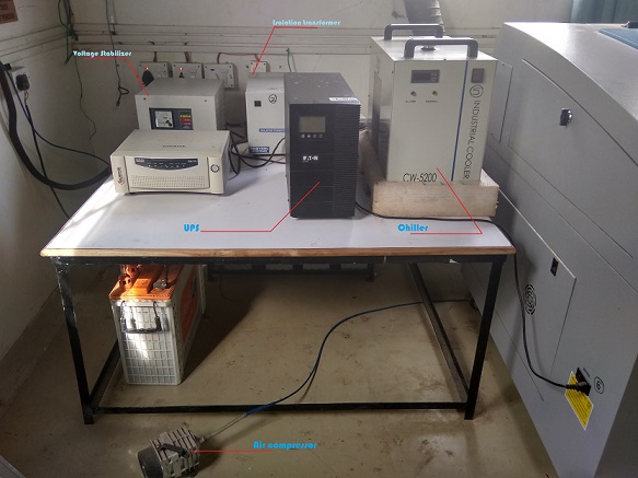
The machine works on a standard single phase AC supply of 230-240 volts there have been a special setup made of electric components and stabilizers since the parts of the machine are extremely sensitive and the point to which it has been plugged have a highly fluctuating voltage(below image describes the parts)
The machine works on the basic priniple of photon generation i.e the lazer is created as result of electron bombardment
over the anode surface(i.e when the current is supplied through the circuit electrons travel from cathode to anode at a
specific frequency and velocity, which on a sudden impact and production of photons and energy)
the entire process takes place in a chamber filled with CO2 which usually acts as a medium of flow for the electrons
The light is transmitted to the engraver through various mirrors which work on the principle of a periscope, which is futher
focused using a concave lens, in the engraver.
The engraver has a bed size of 3 X 2 feet
Group Assignment
For this, the group tested following things...
- Kerf at different power and speed for
- MDF:- For MDF we tested making 8 squares and tested them at varrying speed between 22 to 28
and power between 55 to 67,
and got the best results for the speed of 26 and power of 59, where the kurf achieved was only 0.15mm
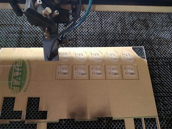
- Acrylic 6mm:- For this we made two patterns one with varrying speed, other with varrying speed
The first pattern was having a constant power of 62% and speed ranging between 8 to 12
The other pattern was having a constant speed of 8 and the power ranging between 55% to 70%
For this we got the best results for a speed of 8 and power at 68% with the least kurf of 0.3mm(though it is actually high if considered)
- MDF:- For MDF we tested making 8 squares and tested them at varrying speed between 22 to 28
and power between 55 to 67,
Problems Faced with the engraver
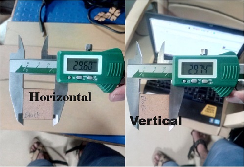
- The engraver has a very high amount of kurf lining, this was mostly seen due to constant loss of focus after a vertain use of the engraver
- The kerf seen vertically is different than the kurf seen horizontally
- The parameter of the settings changed on the panel board of the machine differ that to the parameters, considered in the software (RD Works)
EPILOG Engraver
This engraver has a small bed size, when compared to the SIL, but it has most advanced functions,
Those include
- A precision with the kerf on every side
- Its made easy to command the engraver through many formats, including *.dxf and *.cdr, or even pdf
- The machine has the ability to engrave on various layers in the 3rd axis of geometry
- It has a very negligible kurf
The Machine has a bed size of 300 X 600 mm
Group Assignment
For the assessment of this machine we decided to stick to the similar pattern of parameters and compare between machines.
For this we made two patterns in which we once kept a constant speed, and later constant power, to measure the difflection in the kurf.
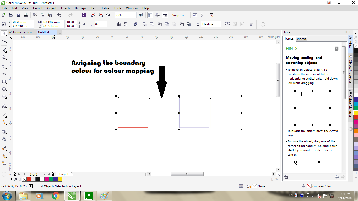
For this to make our work easy we used colour mapping where we added colour to the boundary, and specified it's properties individually..
There are few more steps required inoder to worl with epilog, which are mentioned below:-
1. Once done with the adjustments of the design hit Ctrl + P, to open a menu as shown below, and follow the steps in the image
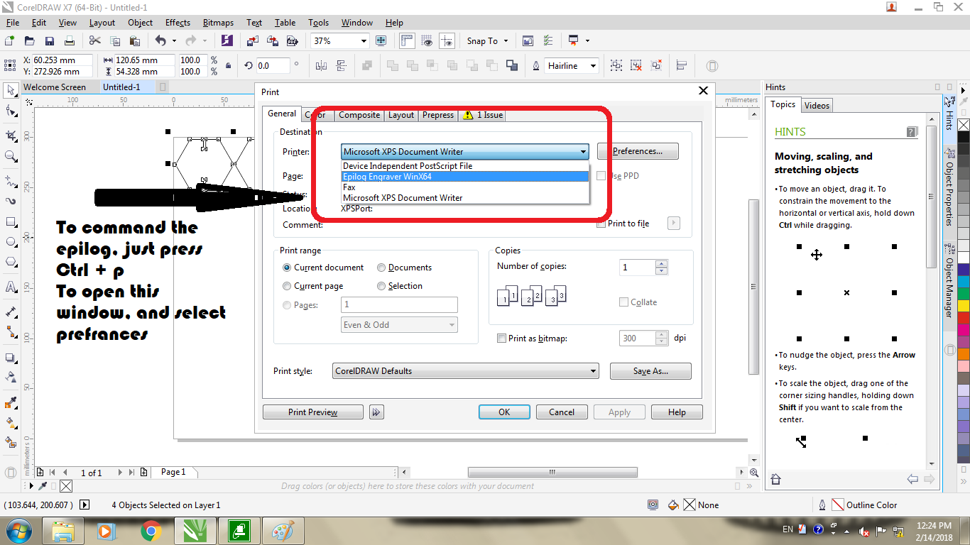
2.Once done with that select prefrences to get a menu as shown below and manipulate the parameters (guided in the image) as required..
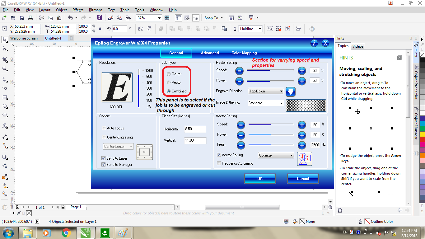
3.Then just hit enter, set the origin on the engraver manually and press go.
Hence we made patterns for kerf calculation and got following results for individuals:
- MDF:-
For this we decided to keep the power constant, and varry the speed between the range of 30 to 60 percent as shown in the image about colour mapping..
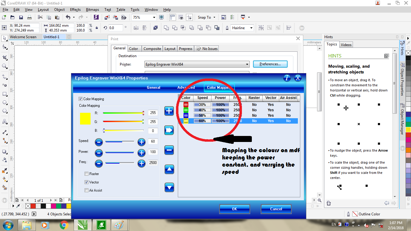
The following were the results we recived about the difflection in the kurf
Out of which we concluded that 100% power and 50% speed was ideal for minimal kurf of 0.14mm
- Acrylic:-
For this assessment we did the same where we used same shapes of 40mm X 40mm with changing colour maps, as shown below
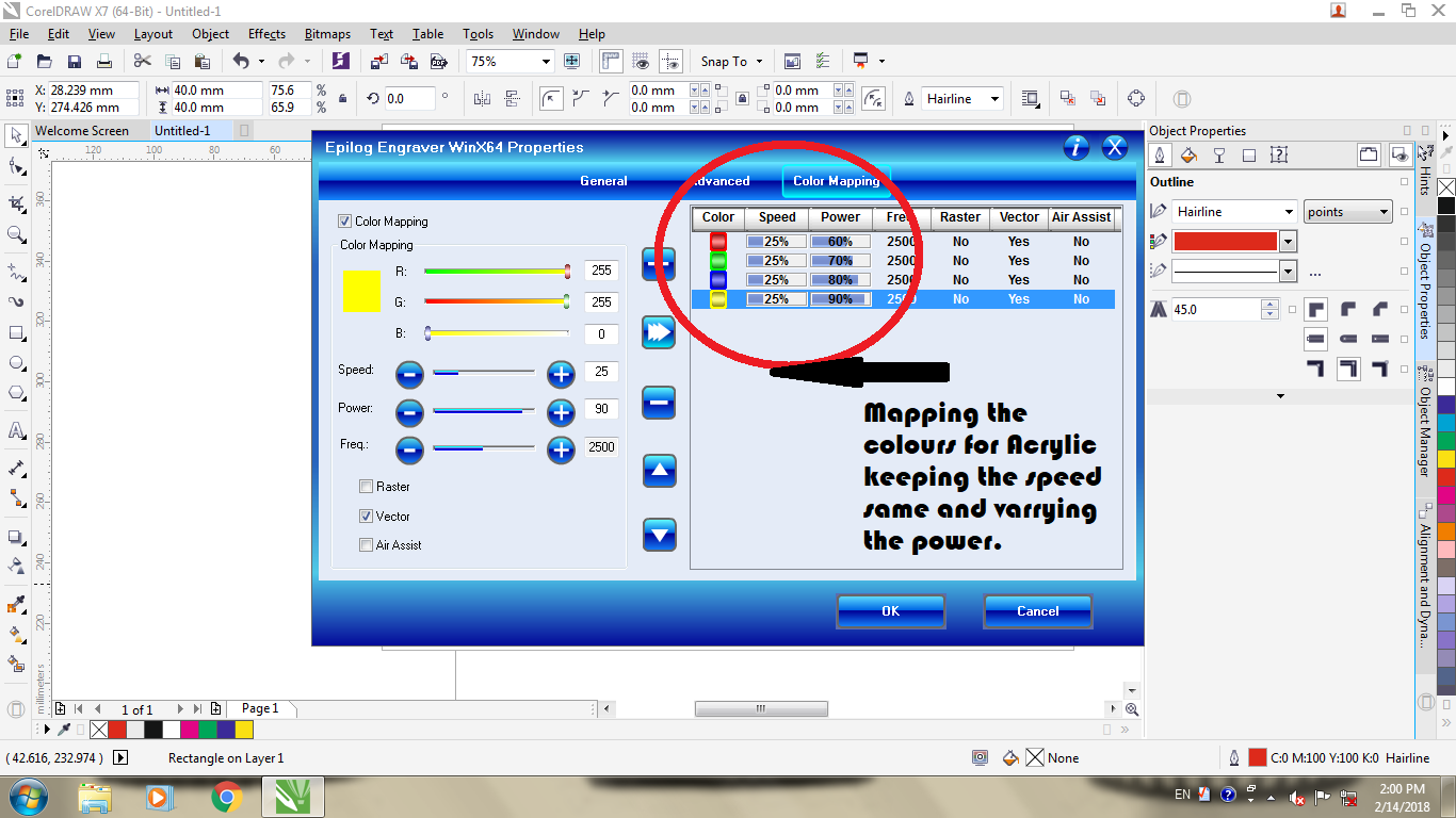
For this we had to feed the machine with multiple passes, which actually exceeded upto 8 passes, for the powers and speeds we wanted to test
After 7 to 8 passes we got the cut outs to produce following results...
Out of which we concluded that at a speed of 25% , the ideal power is 80% to achieve a kurf of 0.13mm
Conclusion
Hence following was the information about both the machines which we used and the problems faced during the process.
Task 2:
Learing about parametric designs.
Concept
This is type of CAD Desing where there are parameters and contraints assigned to the design, which are inter related hence if the main guiding dimension changes the entire sketch changes as per the ratios assigned, these can be changed using relative dimensions or even by making patterns or mirrors that work on the same principle
Key points in the process:-
The above set of GIF images show types of parameters that can be defined in a 2D parametric design...
FOR Example:-
- The image of a round edged square guides you throught the idea about how you can relate the dimensions over each other,

To do this you need to insert the smart dimension tool, and there you define one (guiding) dimension as whole number, and the other (driven) dimension as an equation with respect to the guiding dimension.
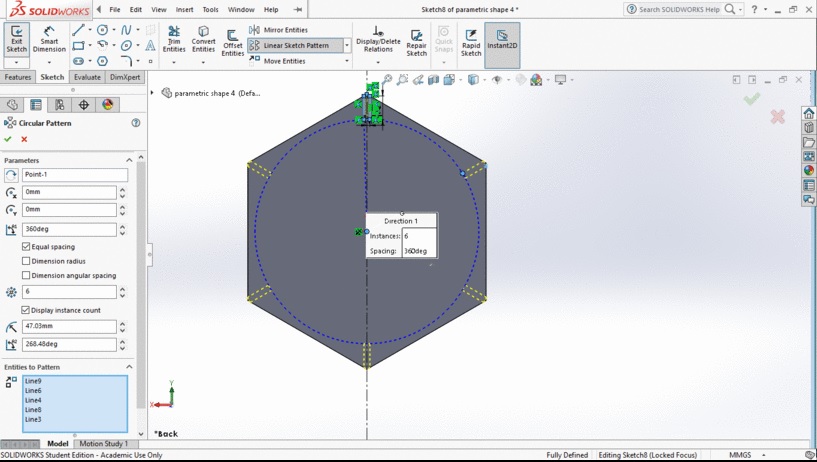
{ Here the relation of driven dimension with respect to guiding dimension is D2(driven)=D1(Drving*1} - The next set of images guide you through making cirular patterns, these are helpful when you have to align few holes or slots, aroung a particular axis and each of them have to be so related that the entire pattern changes on changing of one dimension..
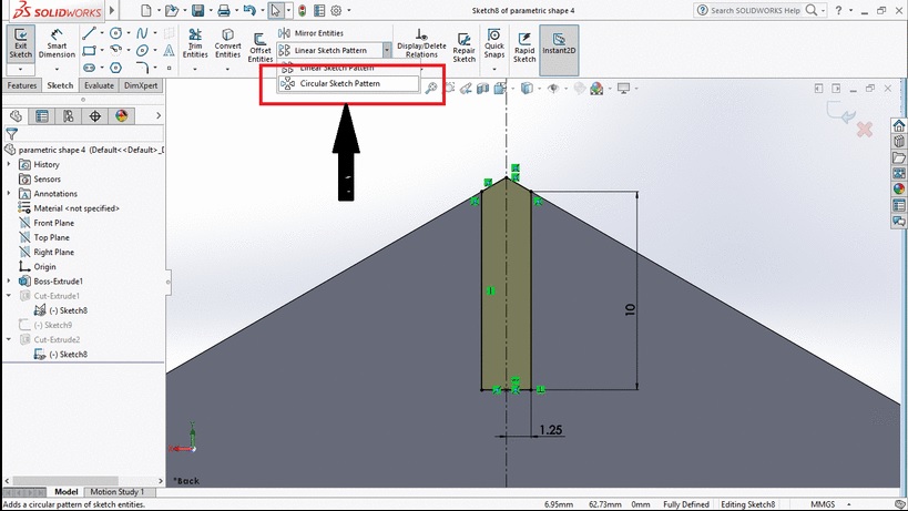
Here you open a dialog box where you define the difference of angle between the patterned figures, along with the distance and number of figures to replicate..
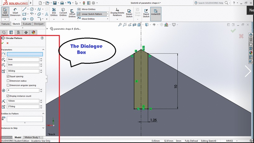
Finally when you conclude with the dimensions you get a simulation which can better guide you through a visual assistance that could help you change required parameters to achive desired fiqure
-
The next image is an example of linear patter as well as mirror, Here the trapezium drawn is an example of mirror command where you draw a single side along a particular axis and then mirror the image aroud that particular asix to ensure maximum semetry.
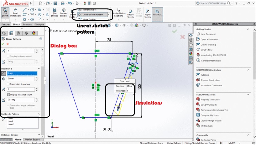
The next thing seen here is the line pattern which is eactly similar to the circular pattern, but helps you to genrate replicas in a linear dimension
Conclusion
All of the above seen patterns are created to make the dimensions interdependant so as when you alter one dimension the entire set of sketches get adjusted in the ratio defined.
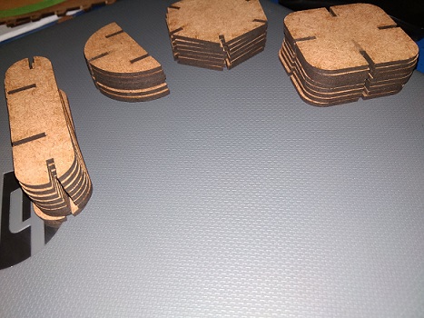
Jigsaws
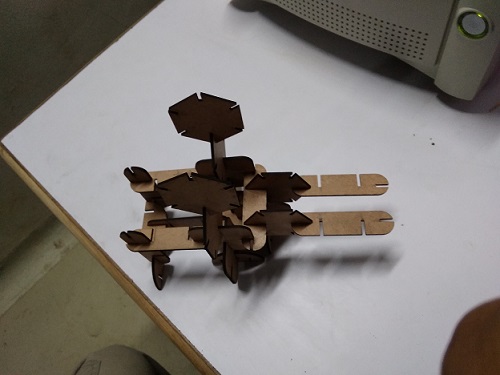
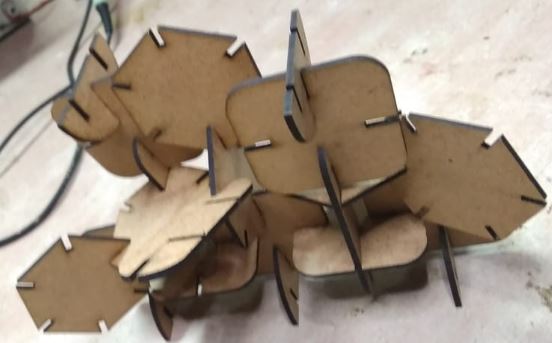
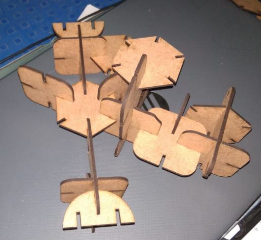
The core task was to develop a kit of 3D jigsaws that can be randomly arranged to generate various shapes(images of jigsaws)
The best way to go for the designs like these was using the method of parametric design, since
the size of the slot and the thickness of the material has to be changing relatively with
the availability of the material(files at the end of the data)
For the following, the software that i used was solid works by Dassault systems, through which i designed the press fit
jigsaws, and exported them to files that could be fed to the laser engraver
For this initially i had made normal slots as press fit jigsaw kit, but later when introduced with few more types of the joints, i decided to go with them and try if they are actually fissible as they seem.
Following were the joints i was successfully able to design, but later when i decided to execute them I faced the following problems.
- The initial problem started with material selection, the one which i tried behind these joints and the problems i faced with individual are listed below:-
- MDF(3mm):- This material is verfy week and the type of flexibility this joint demands cannot be provided using MDF
- Acrylic(3mm):- This material is one of a good material that has good amount of strength and flexibility equally but the problem with this was the joint was having a week bond with a length of 1mm and high rigidity at 2mm
- Acrylic(6mm):- This material had supported me the best in terms of strength and flexibility equally but then then was still a breakage when i tried to insert the press fit designs since the bonds at the fulcrum point were not as strong as expected.
-
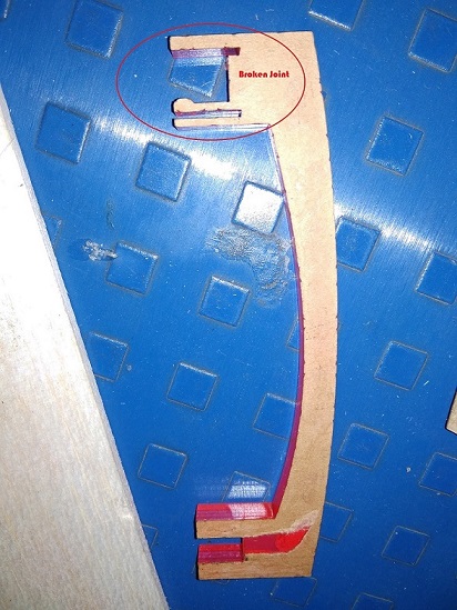
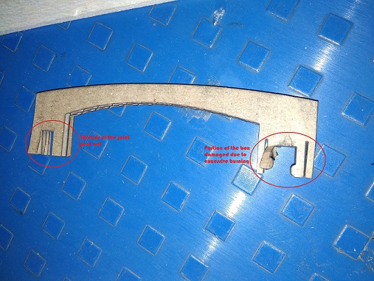
The next material i experimented was cardboard, (which we only had out of the [packing boxes)
This material was flexible and had quite of a strength, but the main issue with this material was, since the joints were too close, hence the kurf of one used to burn the border of the other and hence the joints were simply crushed in the hand
- The next i went into exploaring was balsa wood, this is quite similar to cardboard just, is just a bit denser to it
yet similar was the problem with it as t was faced in MDF that the joints were too week
- MDF(3mm):- This material is verfy week and the type of flexibility this joint demands cannot be provided using MDF
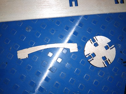
- The second bigger problem was about the desings of the slots, initially i had made an attempt to just undertand the concept of each slot and then when I desired to test each of them there were severe problems seen.
- The first joint i tired was the one mentioned below..
The problem of whose is explained in the image.
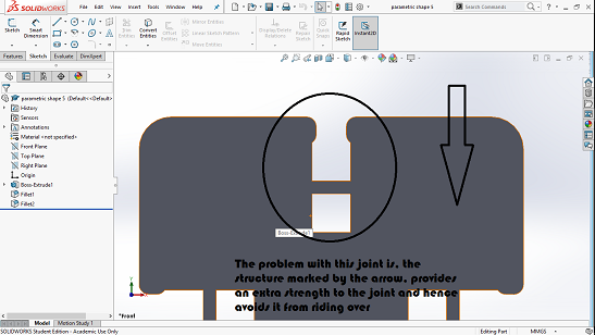
-
The other was the joint i which broke for most of the time, due to lack of strength
THe image explains the problems of the joint
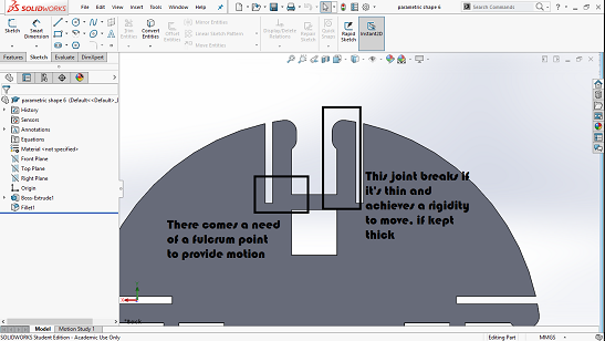
- The first joint i tired was the one mentioned below..
- After this i had reached to a conclusion, which stands as:-
- The joints have to be perfectly engineered before being created
- The material of the joints has to be elastic as weel as strong enough to sustain the force being applied
- There has to be a proper dimentions for each of the (major and minor)slot, where the moving slot wont have to travel much while opening yet would snap inside whenit rides over the another slot
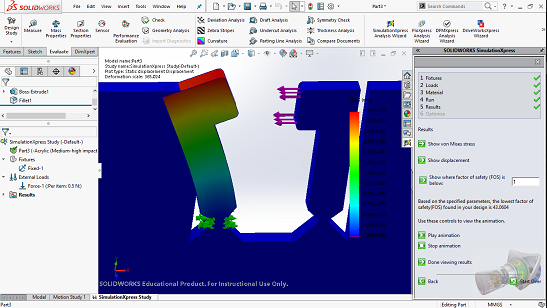
- There has to be a very strong fulcrum point for the joint where the entire stress generated by the bending moment can be compensated, as i tried in the simulation below....
- Hence due to the following issues that i encountered I decided to stop for a moment re-explore the joint and make it happen if i get time, and stuck to the traditional slots
Hence following are the designs which I made out of MDF and assembled them to try and make a jigsaw in diff ways possibleFor the same I used the data driven from the group assignment regarding the power and the speed:-
Which for the SIL laser the ideal was considered to be..
Power:-59%
Speed:-22mm/s
Process of making the jigsaws
For this initially the kerf of the machine(excess material lost during the process) had to be calculated,
This has to be done since, since press-fit kits have a tolerance of 0.02mm, so as to work perfectly
Hence i calculated the kerf of 3mm Acrylic and 3mm MDF which turned out to be 0.3 and 0.2 respectively.
For that we conducted a test as a group assignment1;
where we calculated the kerf for both the machines, on Acrylic and MDF for cutting and engraving, respectively.
After this the task was to edit the dimensions of every slot and then try and test each component, instead what i prefered was the method of giving compensation, i.e setting an offset of the figure equivalent to that of the kerf, hence the lazer moves from the outer edge and the initial job is preserved. The folowing image guides through the process of giving offset
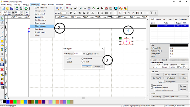
This eliminates the tedious work of setting the dimensions everytime. And the possible loss of time and efforts.
Reason to use offset:-
Initially there was actually not a need to use the offset, since the design was parametric and there was full chance of editing the design according to the kurf found, but there were these following reasons beacuse of which the use of offset turned out to be boonful for me..
- As discussed above the machine gave a varried set of kurf both in the x and y direction, hence editing the entire design on the respective level would have disturbed the parametrics of the design, that would have hampered the repeatability, of the job.
Thus I just edited the offsets on respective sides, as needed. - Also the kurf delivered by the machine was not constant at every repetation, for which we had to render the offset at almost every instant, that would have been difficult to get it done on the design end, and hence I preferd to use the offset function
- Another issue faced was with the material stock which showed random variation in the thickness since was purchased from the local market, there was a recorded variation of 0.7mm across the length in the 3mm mdf sheet.
- And besides that helped me to understand what are the functions of offset and how the machine functions to the respective offsets
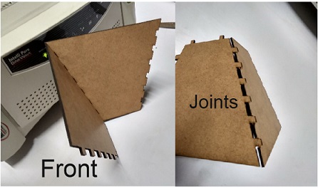
Sub Task:-To try for the project parts:
Most of the static parts are meant to be constructed in the form of press fit joints, hence to test the basic ones of them, i tried to generate the hoppers of my project, using the knowledgeof parametric designs and laser cutting learnt above..
Hence after designing the parts as expected and simulating their assembly, i made first two sides of the hopper in MDF just to test the joints, where as the entire project would be cut in 3mm Acrylic sheet, which I had planned to fabricate in while developing the final project.
Hence I kept the part of the project aside and continued to vynl cutting.
Task 3:
To learn and explore vynl cutter
Sub Task:-To learn about vynl cutter
The vynl cutter we have is ROLAND ... , which is a pretty old fasioned cutter who has most of its drivers in windows 7 or even in XP, it has a horizontal bed size of 450mm.
There are two basic parameters that are supposed to be manipulated at basic levels to obtain a basic result
1. Force: This defines the pressure to be applied by the blade over the sheet.
2. Speed: Which defines amount of material to be cut in particular time.
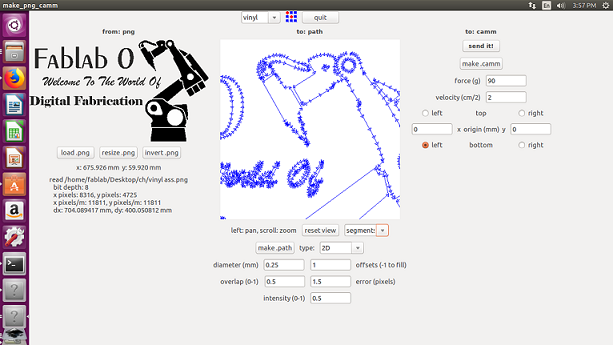
The software which we use is a linux based software named as fab module, to which we add a *.png file and the machine prints the file in the 1:1 scale ratio
and rest include geometrical offset and some other features
Sub Task:-To Design and Cut on the vynl cutter
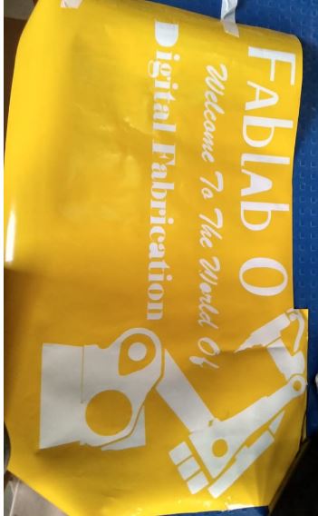
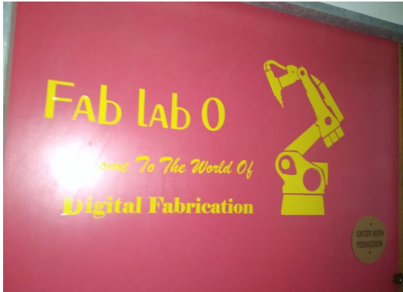
In this task i designed a basic sticker that could be used to decorate the ashram,
hence i decided to make a welcome sticker of size 400mm X 700mm.
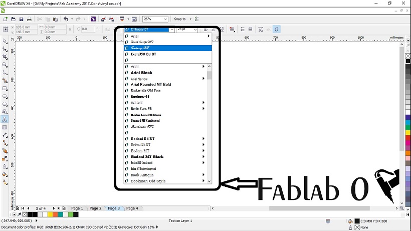
This included basic editing in corel draw, with the knowledge derived from previous segments..
Basically I used various fonts, and editings to render the written matter..
For the Arm I got this image from google images about digital fabrication, which I had imported in the corel draw.

After this now I just wanted the vector impression of the arm, for this corel has a very powerful feature of image tracing, out of which I got the arm as i needed..
To enable the function you select the image, and the hit the button of "trace bitmap", that opens you a dialogue, that guides you for choosing the detials and the ways in which the logo could be traced.
Out of which I chose detail logo trace, that guided me through a window.
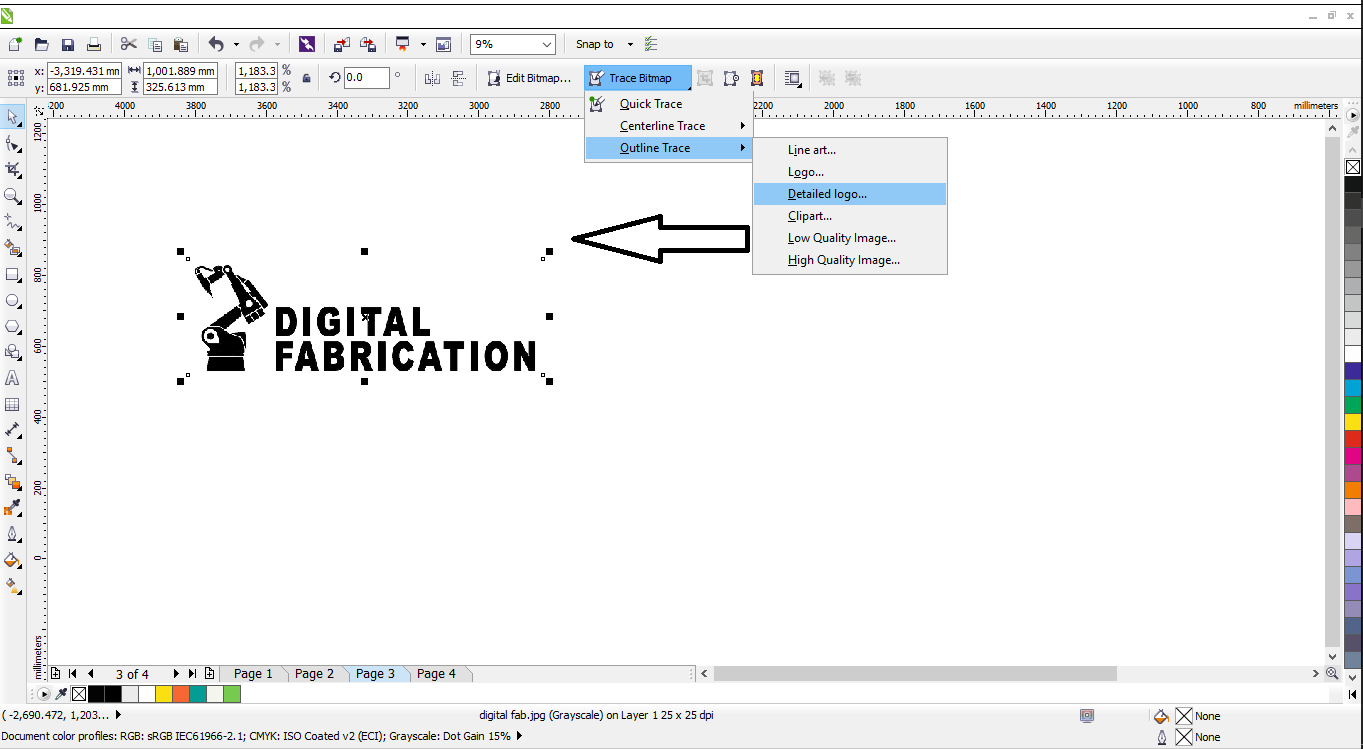
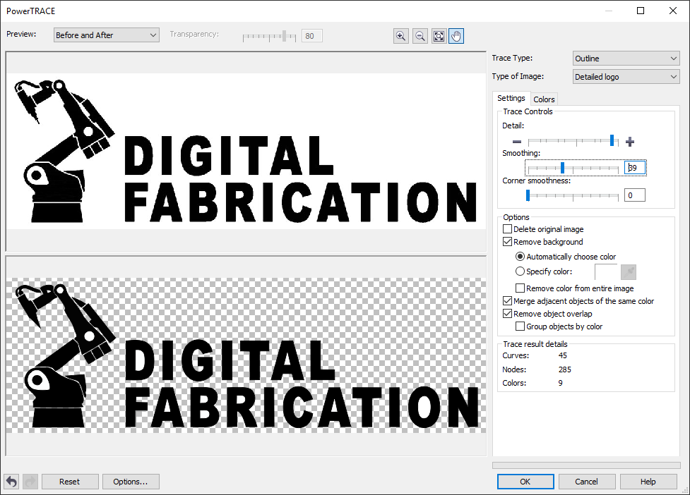
After which I just edited the three bars that defined the quality of the trace and clicked on trace to get this as my final image, which is seen in the poster.
Following was the sticker I designed:-

Later the task was to cut it on the vynl cutter,
For that we used the fab module through linux, because the drivers were formatted in the initial system.
For that we have to enculcate following steps:
- Import the image
{Note:- The image required is in *.png format, and has to be of high resolution in order to get a fine cut} - Generate the path.
- Setup necessary speed and force {Force - 90 and Speed - 2(in my case)}
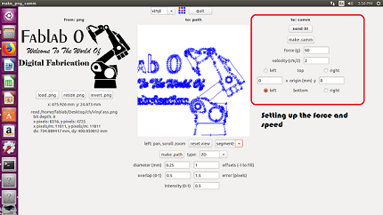
{Note:- The speed and force altered on the software, overwrites the force and speed settings on the machine} - Set the origin for the tool on the sheet and Send the image as a tool path to the cutter
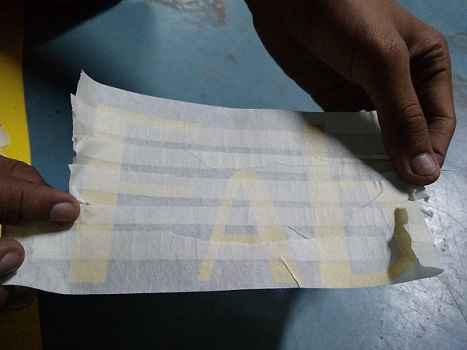
- Then once the cutting is done the step that remains is to peel it off perfectly,
This actually became bit critical for me since I had used cursive and exotic fonts for the design to be creative, yet with some help of the batchmates, we pulled off the sticker using the masking tape, Which looked like this.
Following were the steps you have to go through, in order to get the sticker printed, there were a few errors in the machine which i noticed;
- The machine looses its origin after a while and changes the direction of the print which gives errors in the design
- The machine also generated offsets when it is started on a re-cut, which intern damages the design again.