Aim:
To understand the working of a Micro controller and Program it.
Task 1:
Understanding the datasheet of the respective IC
What is a Datasheet
Datasheet is basically a detailed explaination about the functioning of a particular IC, and details about it's components and
it's specificaions for inputs and output.
In short it can be termed as a 'users manual' for a micro controller.

Sub Task:-Readind the datasheet of Attiny44
The processor that I had used for my hello world board was attiny44 IC (Datasheet included here), it's basically an IC with 14 pins..
After surfing it's through the datasheet I plotted down few conclusions:
- The IC operates on a voltage range of 1.8 to 5.5Volts, where the clock speed differs as the power increases (upto a certain limit)
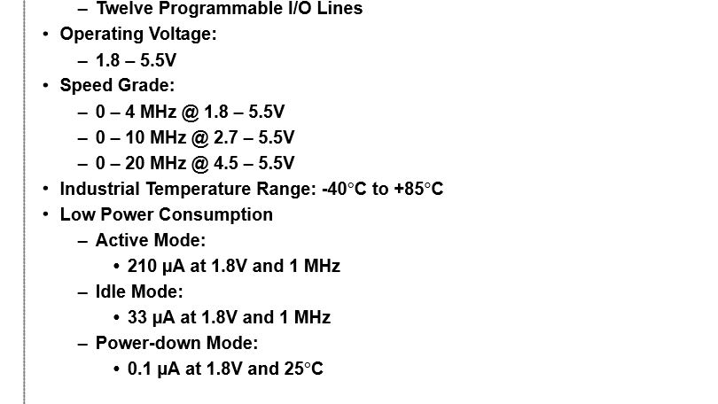
- It is a 8bit processor, having an on board programable watchdog timer(electronic timer used to detect and recover from computer malfunctions) and an analog comparator(A device that compares two voltages and displays them as digital signals(1,0) as which is greater)
- The datasheet gives you the pin configuration, which helps you in the alignment of the component while soldering and solve much of the issues related to programming, one of which I had faced (mentioned below)
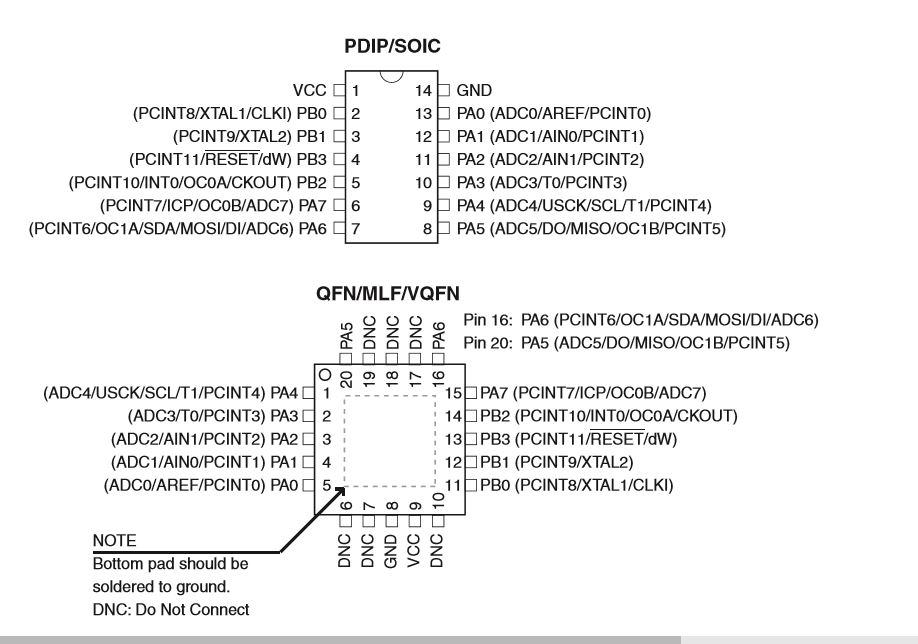
- The IC has few dedicated pins which are necessary for loading the drivers and the program to the board, namely{MISO, MOSI, RESET, SCK}.
The 'GND' and 'VCC' are common pins - Also here are few basics I understood about details about the pins.
- VCC:- The pin where the voltage is supplied
- GND:- The pin which is treated as the ground pin
- PORTS:- If noticed well the pins are bifurcated in terms of A and B, where each group has some of its own abilities..
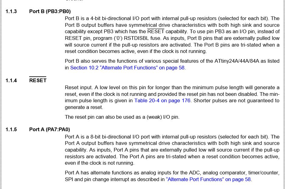
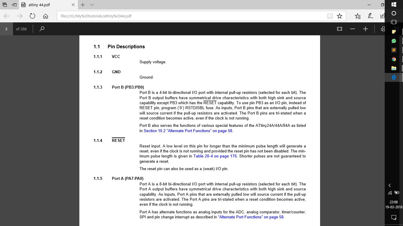
- PORT A:-These ports are 8-bit bi-directional ports, they have similar basic characteristics to that of PORT B, but differ by having the alternate functions of ADC, analog comparatot, timer, SPI, etc
- PORT B:-These ports are 4-bit bi-directional ports, having similar characteristics, but have a pin dedicated for the reset button, which when pressed resets the board to a digital value of (0), by making a mechanical short.
- The next thing to be taken into consideration is the architecture and basic functioning of the IC.
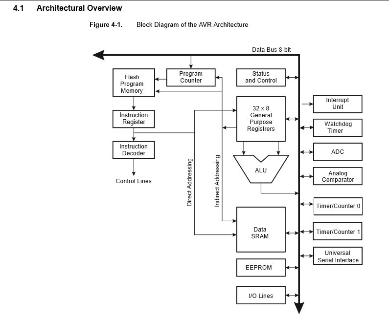
1.This particular IC has a Harvard Architecture with seperate busses and memories.
2.The program is so developed to pre read the next line of program while the first line is being executed, makes it easier to run the clock cycles.
3.The program is saved in the "Flash Memory"
The rest of the needful information can be found in the data sheet (link attached above) - The next thing about the basic strata about the functioning of the memory
The flash memory is organised as 1024/2048/4096 X 16bits, with an endurance of 10K cycles, i.e it can be programmed 10,000 times
Rest all was a bit of the data which had became quite difficult for me to understand, as it was bit data specific.
But the above mentioned was something that caould be used and unserstood by anyone.
Task 2:
Programming the Hello World Board
Sub Task:-Programming with Arduino IDE
Before going into programming let's understand what is ardiono IDE..
It is basically a peripheral that communicates between the hardware and the software interface having a very user friendly UI.
It basically has it's necessary command arranged in a graphical way to make it easy and interesting for beginners.
Once clear with the concept of Arduino IDE I hopped on to programming the board..
Initially I was bit sceptical if that would work, because I was quite new to it.
So logically what I did was followed the tutorial that could navigate me properly through the process
Link uploaded here
The tutorial guides through the entire process for configuring and programming the board, yet there was a shorter way i followed which is mentioned below.
Basically there are few logical and easy steps to go with the programming
{For the steps to be easy and smooth the hardware on the board had to be perfectly arranged}
- Initally you need to configure your board we here you 1st install the drivers and then select the appropriate settings:
Detailed steps included in the tutorial
The tutorial guide you through downloading arduino manager and then configuring it..
Once done with the installation of the manager, the next step is to select the board and particular processor which is needed to install proper drivers into the IC
For that you navigate to the tools menu
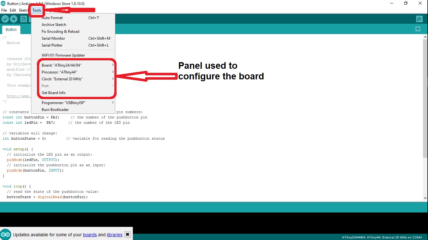
There in the initial menu you see the type of board, processor and the clock speed of the external crystal(if installed) The following gif guides through the settings i used
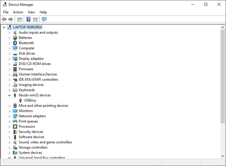
- Then you select the port where the hello world board has been attached. For that you first connect your board with the FABisp and then the Isp to the USB port of your machine, then navigate to the 'Tools Menu', then select the port where you have connected the fab isp
In my case there was only one port engaged but if there are multiple ports, you can ensure the correct port through the "Device Manager" menu in the control panel, where you search for the port of "USBtiny"
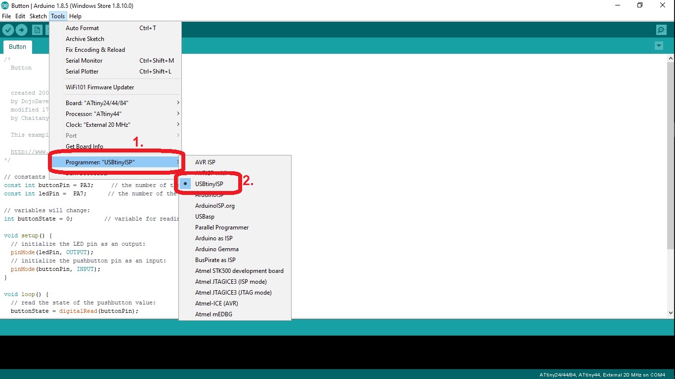
- The next step is to configure your programmer (fab isp as I used)
Here you just select your programmer Usbtiny in my case..
Then steps are same, navigate to the tools menu and then select the programmer as "USBtinyISP
- Then run the command of burn boot loader, this loads the driver configuration as selected above to the IC and you get a message as seen...
For this I preferred to modify a program rather than coding it from the scratch
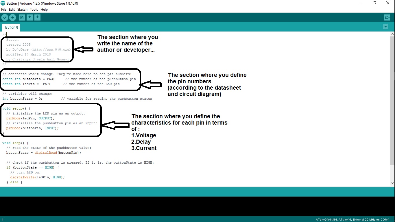
So I initiated the button program which could be found at this path{File -> Examples -> Digital -> Button}
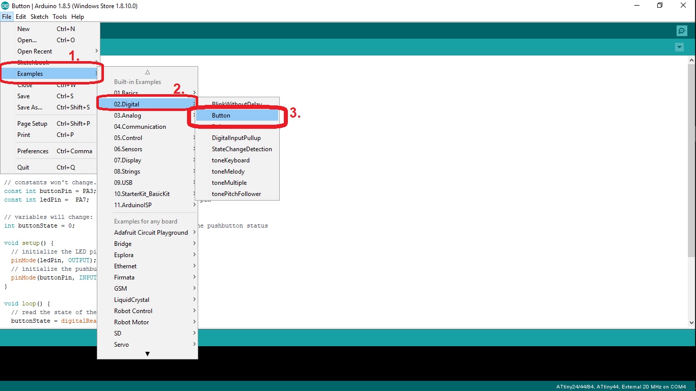
This program basically is about connecting the button to the LED via micro controller, the following set of gif guides you through the elements of the program.
Hence i modified the program and uploaded it to the board, by chaning the pin number as seen in the datasheet of the IC and my circuit diagram
For that the connections have to be as follows..
- The fab isp has to be connected via 2x3 pin headers of both the isp and the hello world board
Where the pins of both the boards match exactly.. - Parallely you need to connect the 6 pin header to the FTDI cable that joins the other USB port..
Where again the pins for both the boards match exactly.
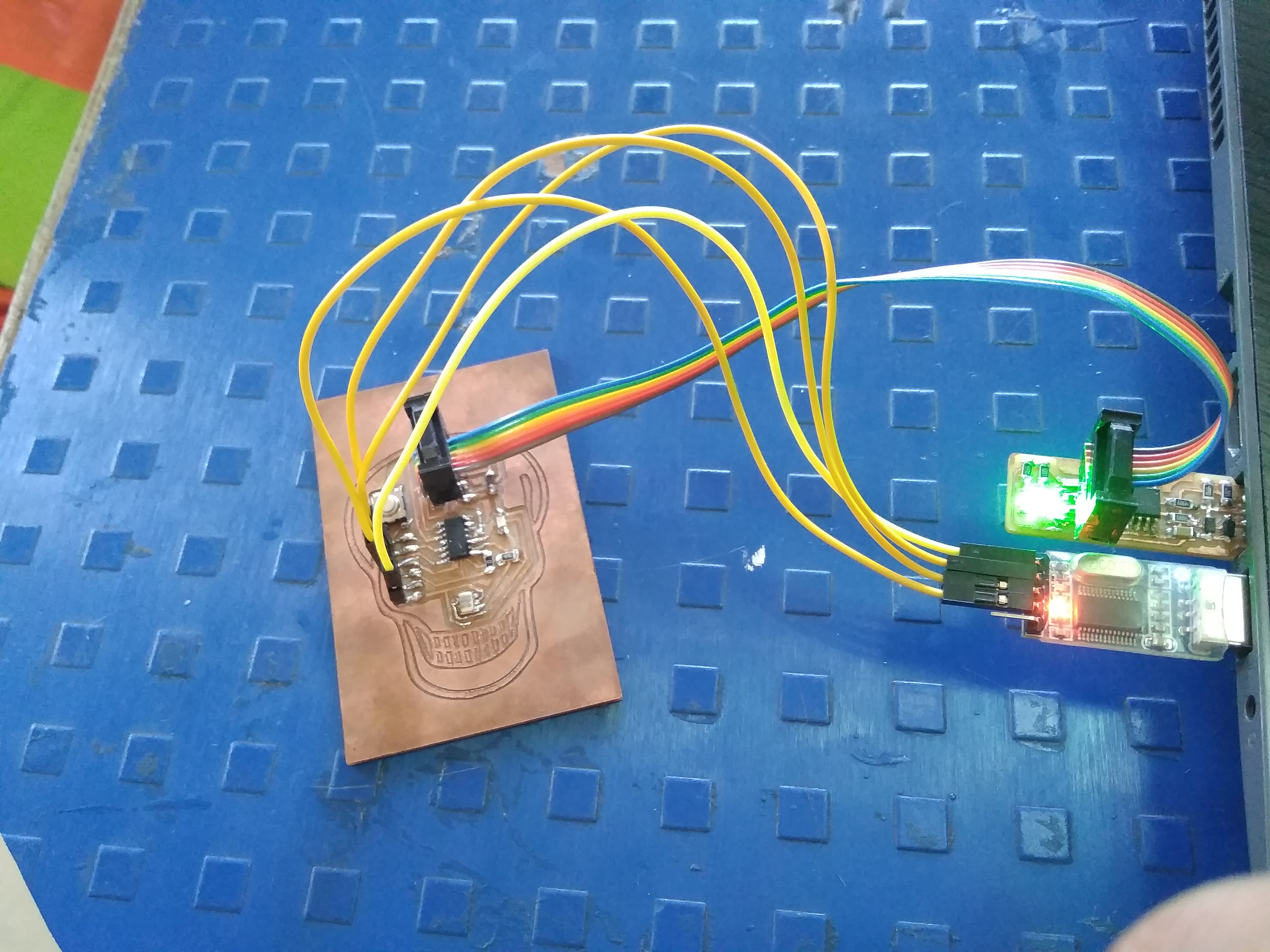
If all the connections are perfectly aligned the IDE displays a message of "done uploading" and the led on the board blinks as shown in fig below..
Problems Faced
There was actually only one problem that had baffled me for a long time,
The programming and the uploading of the program was very perfect due to fewer errors in the hardware
The thing I initially noticed was the Arduino IDE displayed the program has been uploaded but there was no Led lit on the board,
I was in a concept that this had happend because of the miss calculations about the resistance of a resistor, so i had tried changing the resistors, but still had got no results, after which i decided to re-evaluate the datasheet and my program..
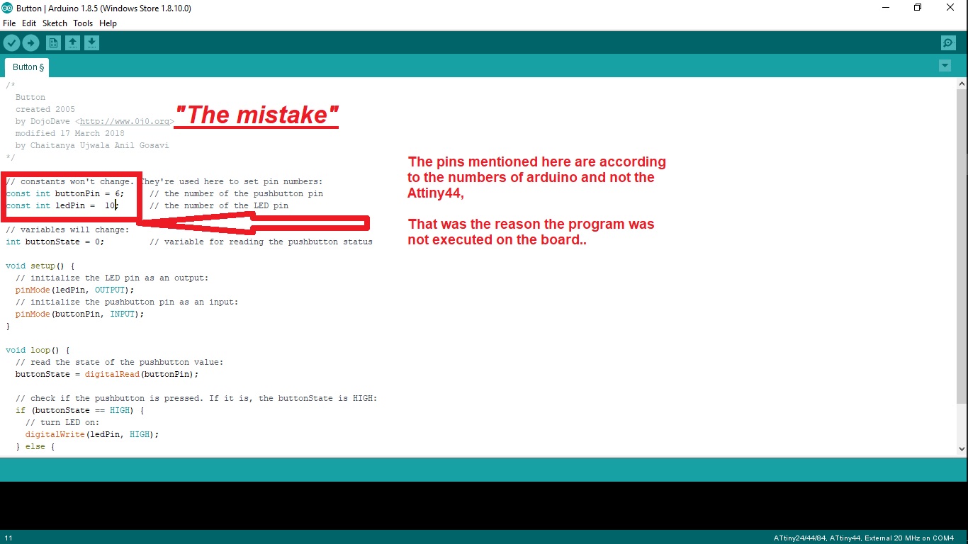
Finally i found that I had named the pin numebers as integers as shown in program above, but later it was seen that the IC does not have any pin numbers like these, the integers are just referances.
So i changed the pin numbers in terms of 'PA2' and so on, which when i downloaded to the IC made the light glow..
Hence following was the result out of the downloaded...
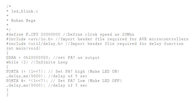
For this here was the code that I had edited out of the standard blink code..
Sub Task:-Programming with C
For this segment also i refered to the tutorial linked here
For this segment I initially tried to download and understand the program written by neil, which can be found on the links below..
But I actually ended up with understanding a very few commands out of it, cause it seemed too complicated, and a lot of commands were written in one go.
So i decided to learn from example codes and try to compile one of my own, for this i refered few sample codes, along with one written by my colleague Rohan, who has explained the method of writing code in terms of hexa-decimal terms..
From here I got an idea to include libraries and define the operating frequency of the resonator, along with the method to define ports and the timings for delay..
But for some points I was finding the method quite difficult to understand, about how and where to find the hexa binary codes for each pin and yet how to define 'if' and 'else' conditions seperately
So after a going through few tutorials I found out the other way round to define the ports, the one viewed here..
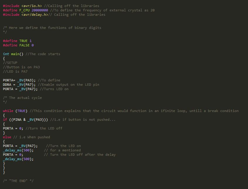
This code includes all the explainations for what each step is supposed to do, that makes it easy to modify when needed.
After this code was done, the next task was about generating the make file, which i later came to know that all the make files function the same so I used the similar file which I had used to copy the test files, using the similar method described in the electronics design week.
After successfully copying the code, this was the result I had got...
Task 3:
Group Assignment
To understand various achitectures of boards
For this assignment we had decided to explore Raspberry pi, it's architecture, configuration and coding it through python..
Sub Task:-Anyalysing the Cofiguration and Architecture
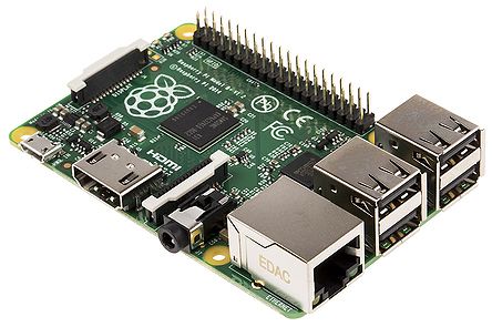
The configuration of the board that we used is listed as follows:-
- Broadcom BCM2835 (CPU & GPU)
- 512MB SDRAM
- 4 USB 2.0 Ports
- Ethernet Port
- HDMI port
- 3.5mm Audio jack
- Micro SD Card Slot
- Micro USB for power
With a CPU configuration reading as:-
- A processor belonging to ARM11J6JZF-S (ARM11 Family), having ARMv6 Architecture
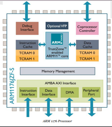
- Single core, 32-bit RISC(reduced instruction set computer)
- Having a 700 MHz Clock Rate
- etc.
Also the following image gives a detail explaination about the components of the core
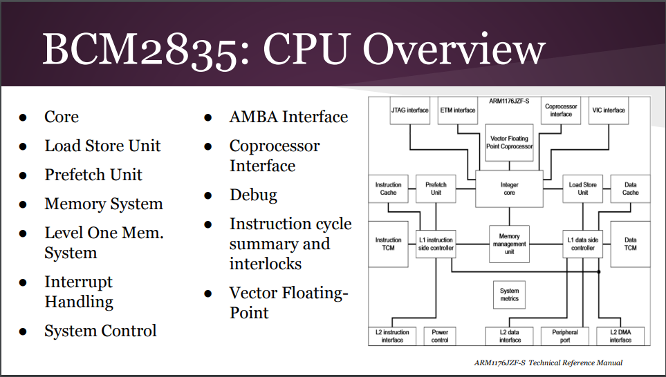
There are few special features that can be listed as follows:-
- The Fetch stage can hold up to four instructions, allowing for prediction to occur on held instructions, this ensures a break free execution of the program without much of a delay..
- Is able to use dynamic Prediction when there is a history associated with a branch
- RPi can play 1080p Blu-Ray quality videos
- Graphical capabilities are similar to the those of the original XBOX
Basically as they say it's a "Credit Card Computer", it is as powerful to run an operating system along with basic applications
Sub Task:-Coding a basic program for blinking an LED
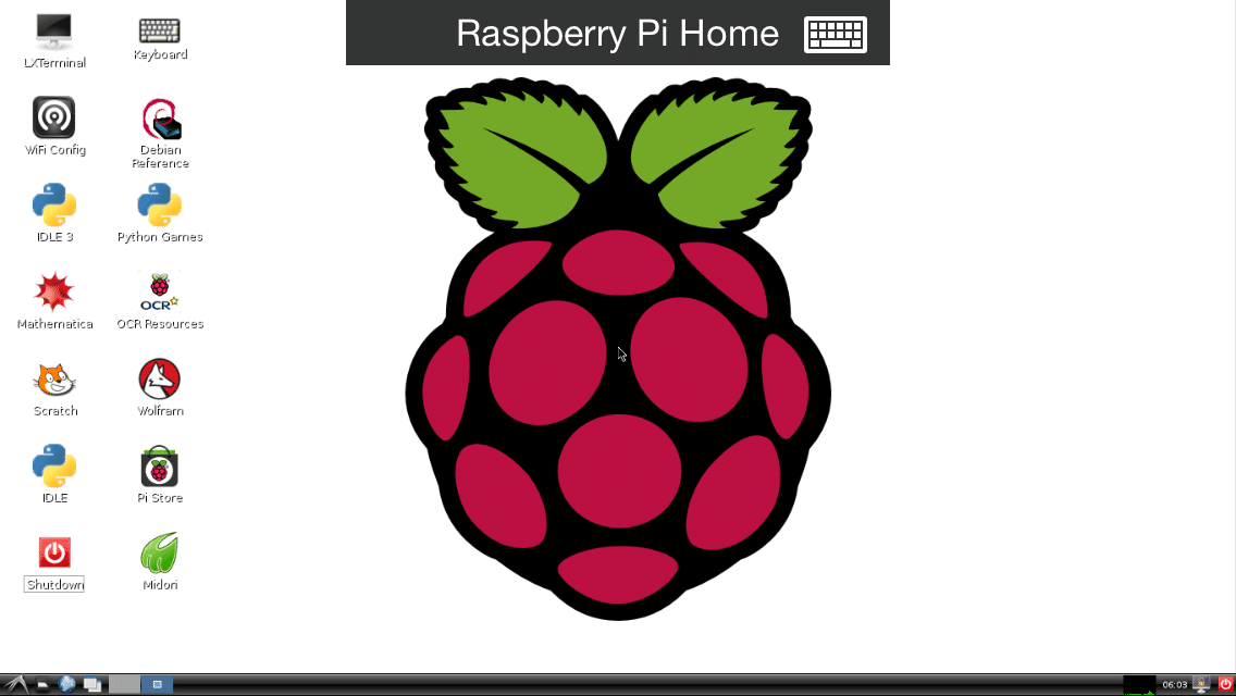
For this we had connected the raspberry pi b+ with keyboards and powered it up, to boot through it.
The OS that we had installed was Raspbian , having a pretty simple user interface..
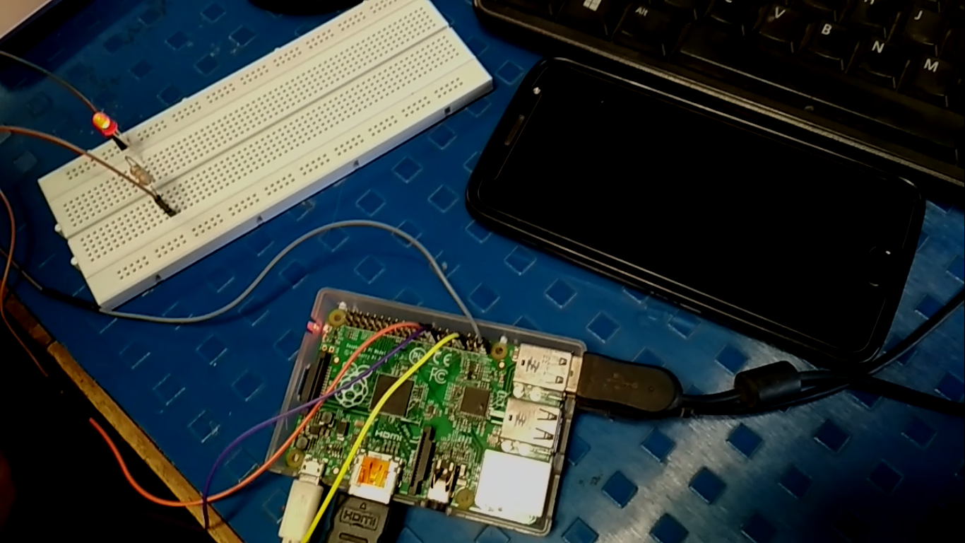
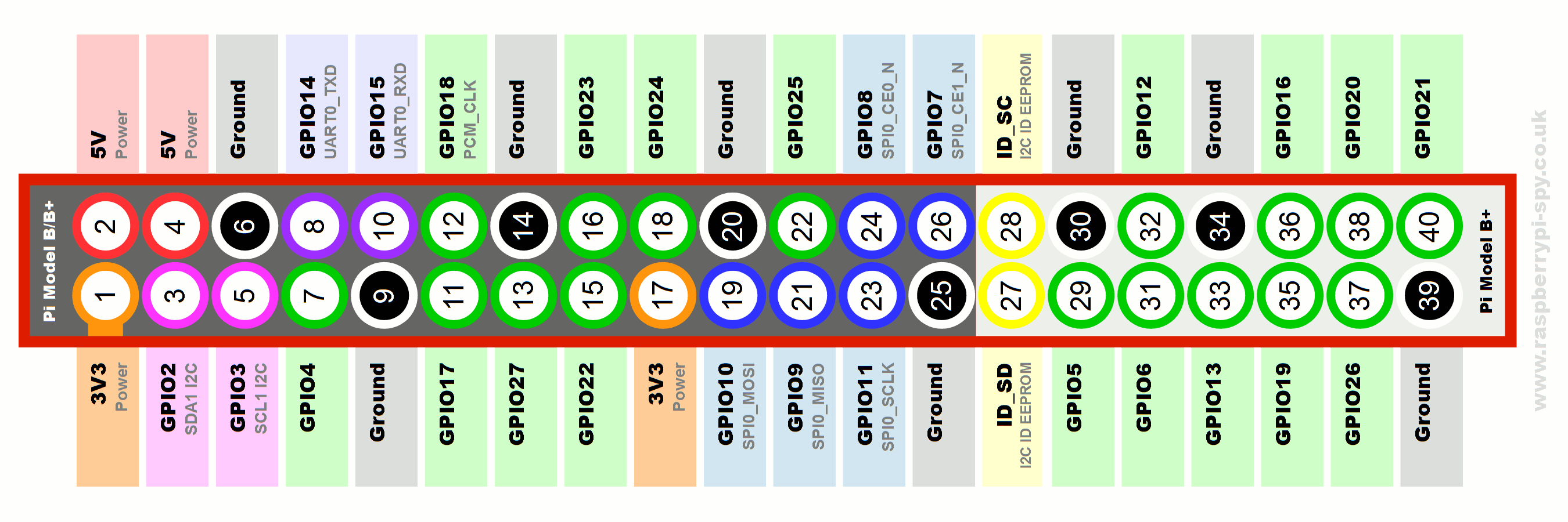
Along with that we had connected an LED to the the GPIO pin of the pi board using a connection on the bread board.
Hence our entire circuit appered to be like this..
After this we wrote a test program for blinking the LED in the local text editor in raspbian
The code was pretty easy, {Written in python}, explained below..
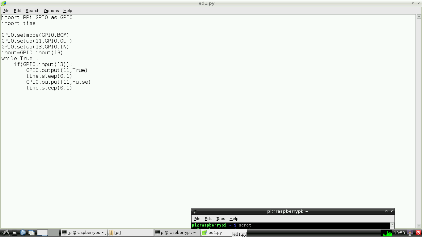
During the compilation the compilation the major challange was to notice the pin that we had plugged the LED onto , and then write the pin number in the code..
This was not quite that difficult but rather confusing because the pins can be assigned. Finally we assigned the numbers in the following order seen here...
Finally we tried to run the program and got the following output...
Conclusion:-
To conclude when I compared the languages of programming I found that python is comparatively very easy to understand and write, having a prety easy syntax.
Also the method of trasfering and executing the program is pretty easy as compared to other methods that I programmed my hello world board.
Also there is an advantage of choosing the program, about what to run, since Raspberry pi has the abilty to store and execute multiple programs, where as the other board overwrite the initial program when other one is loaded.