TASK TO DO:
- Measure the analog levels and digital signals in an input device.
- Measure something: add a sensor to a micro-controller board that you have designed and read it.
- Described your design and fabrication process using words/images/screenshots.
- Explained the programming process/es you used and how the micro-controller datasheet helped you.
- Included original design files and code
Group Work -
Individual Work -
WHAT I HAVE DONE:
INPUT DEVICES -
An input device sends information to a computer system for processing. This week we had to use sensors to measure something as an input device. A sensor is a device that detects and responds to some type of input from the physical environment. The specific input could be light, heat, motion, moisture, pressure, or any one of a great number of other environmental phenomena.
Designing, Fabricating, Programming Board -
By using Eagle and Rolland Modella, I made PCB for temperature sensor.
I want to measure temperature in my project so I decided to make temperature sensor in this assignment.
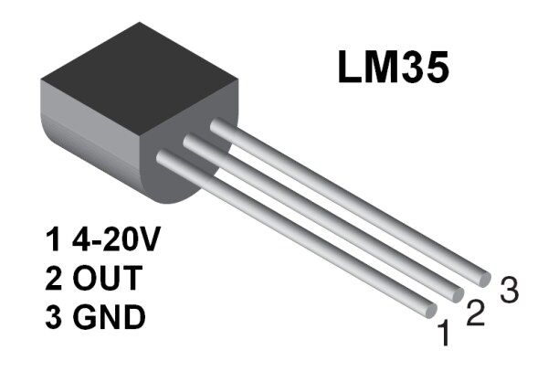
LM 35-
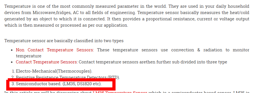
Temperature sensor is used to measure the heat or cold generated by an object to which it is connected.
There are two types of temperature sensor i.e contact and non-contact type temperature sensor. LM35 is semiconductor based contact type sensor.
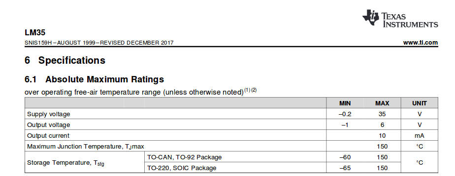
For writing the code I decided to go through the datasheet for LM35.
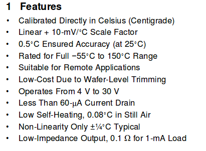
LM35 sensor LM35 device is rated to operate over a -55°C to 150°C temperature range, while the LM35C device is rated for a − 40°C to 110°C range.
It operates on 4 to 20 volts.
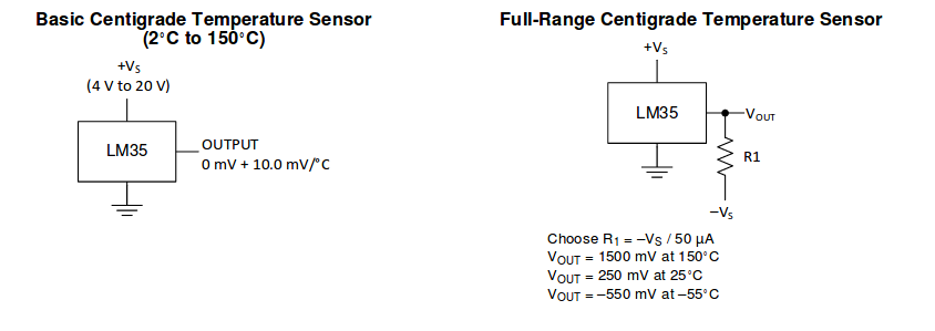
here we can see the full range temperature sensor passing -5v Volts and that night we(in a group) check the output of the sensor.
I added two 3 pin header, one LED and resistor in eagle for schematic. Join them and check the erc which is best feature of eagle.
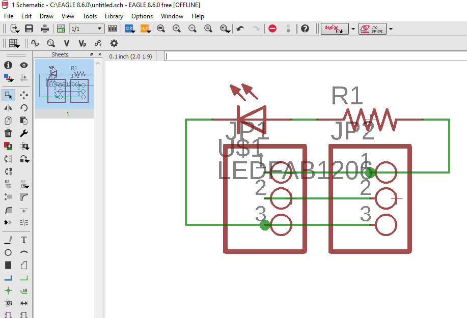
I got no error so I clicked on switch to board. I arranged the components and connect them by using wire.
Then I routed my board and checked the DRC. Here routing is done.
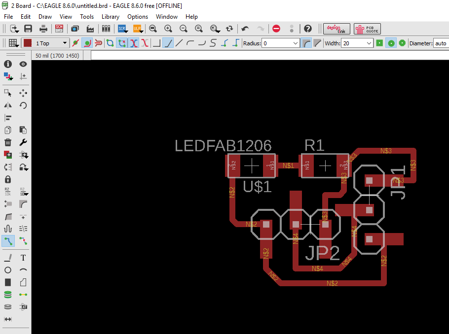
Save the board and border file in .png format.
MILLING -
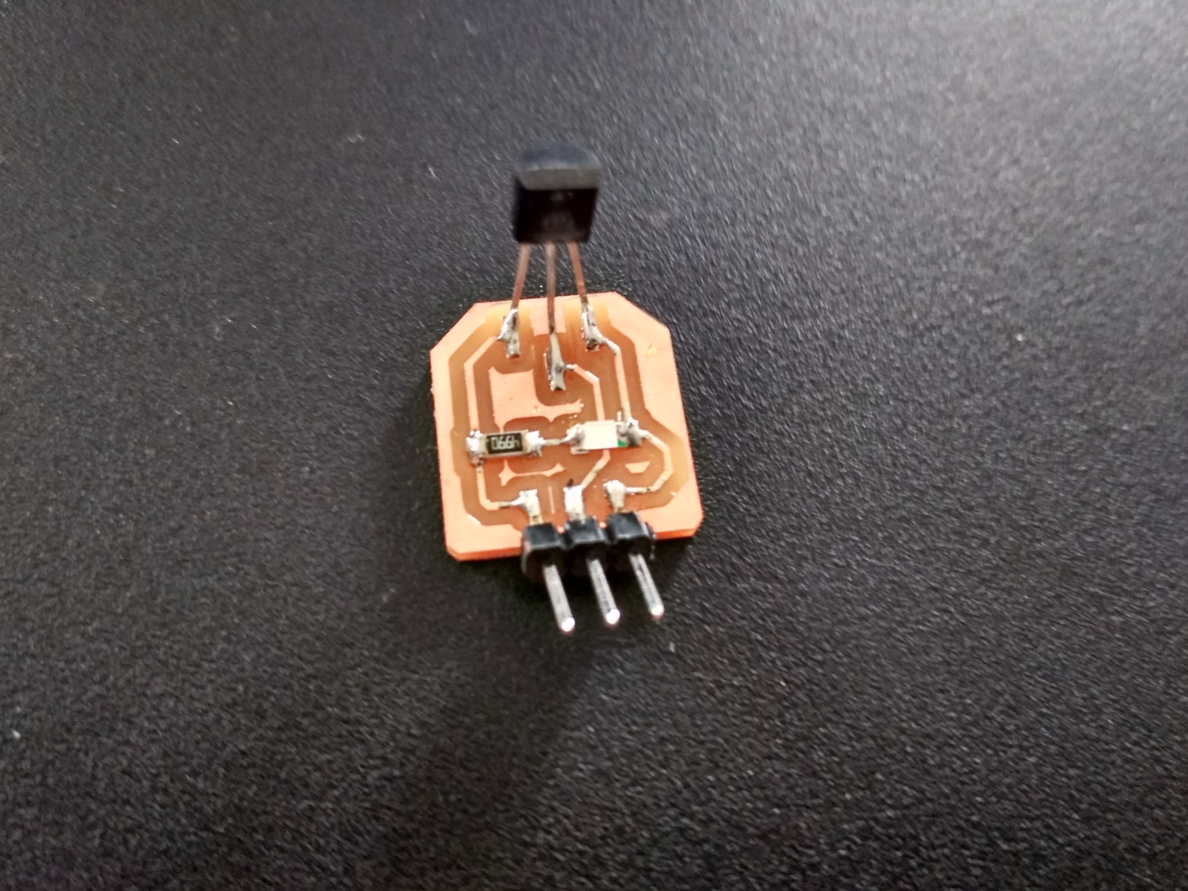
It's time to mill my board. For this, I open the fab modules and load the board file. Make the changes which I want. I milled my board with 1/64 end mill and cut with 1/32 end mill. I milled input board for temperature sensor.
Then I moved towards soldering.
PROGRAMMING-
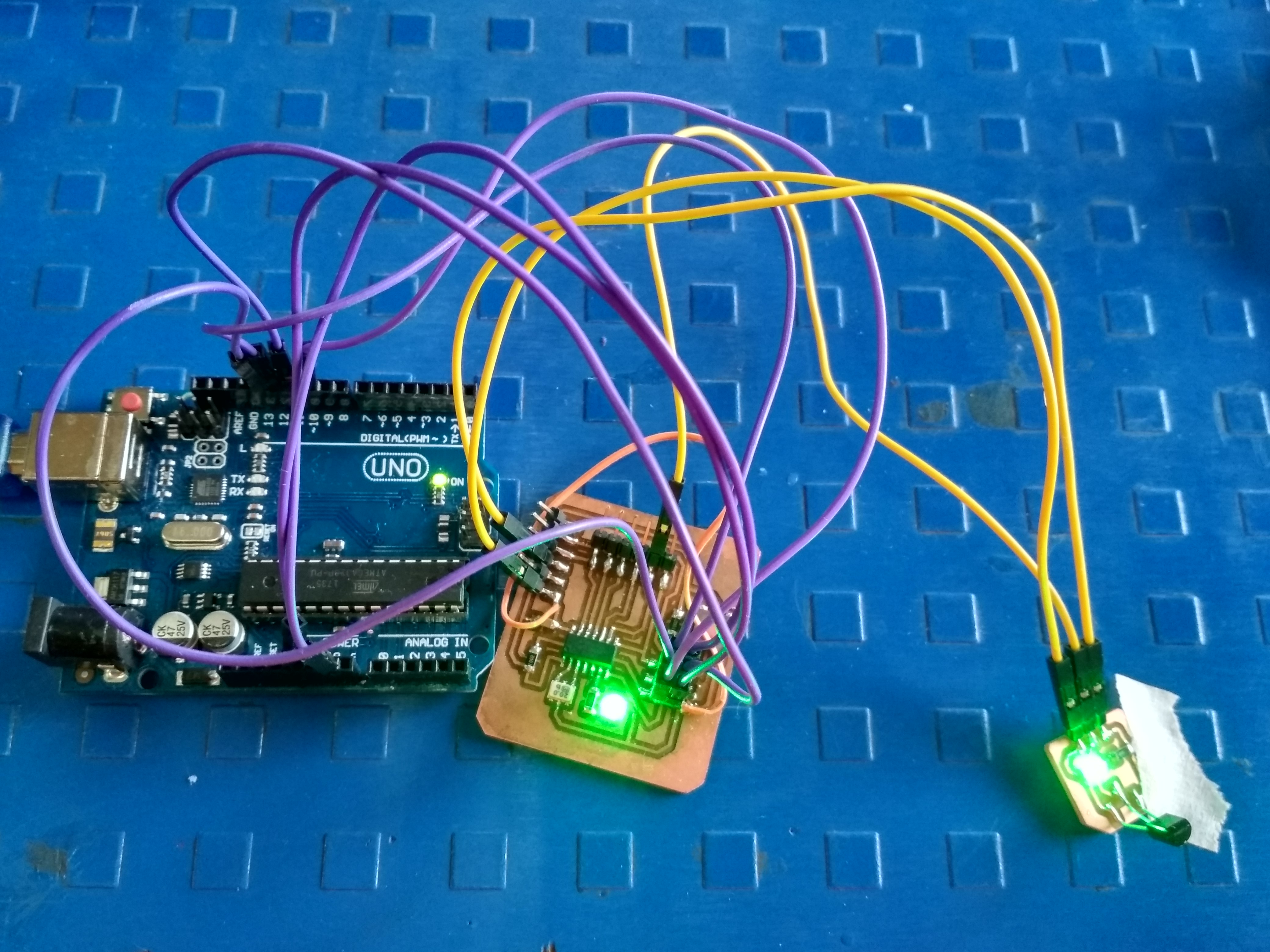
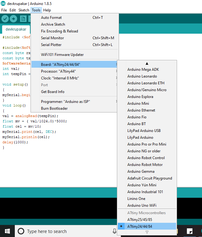
Before programming I checked my board by using multimeter. I programmed my board by using Arduino. I write down the code.
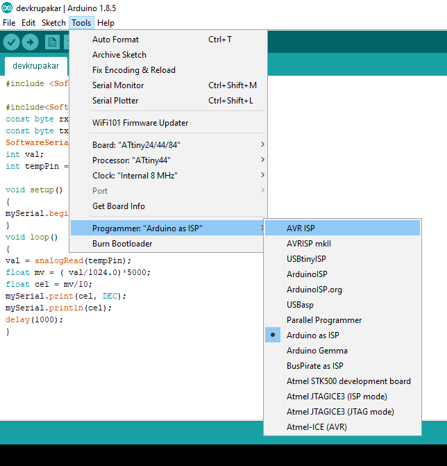
For programming, I used my project board which I milled in Week 7. For programming, I used Arduino as ISP.
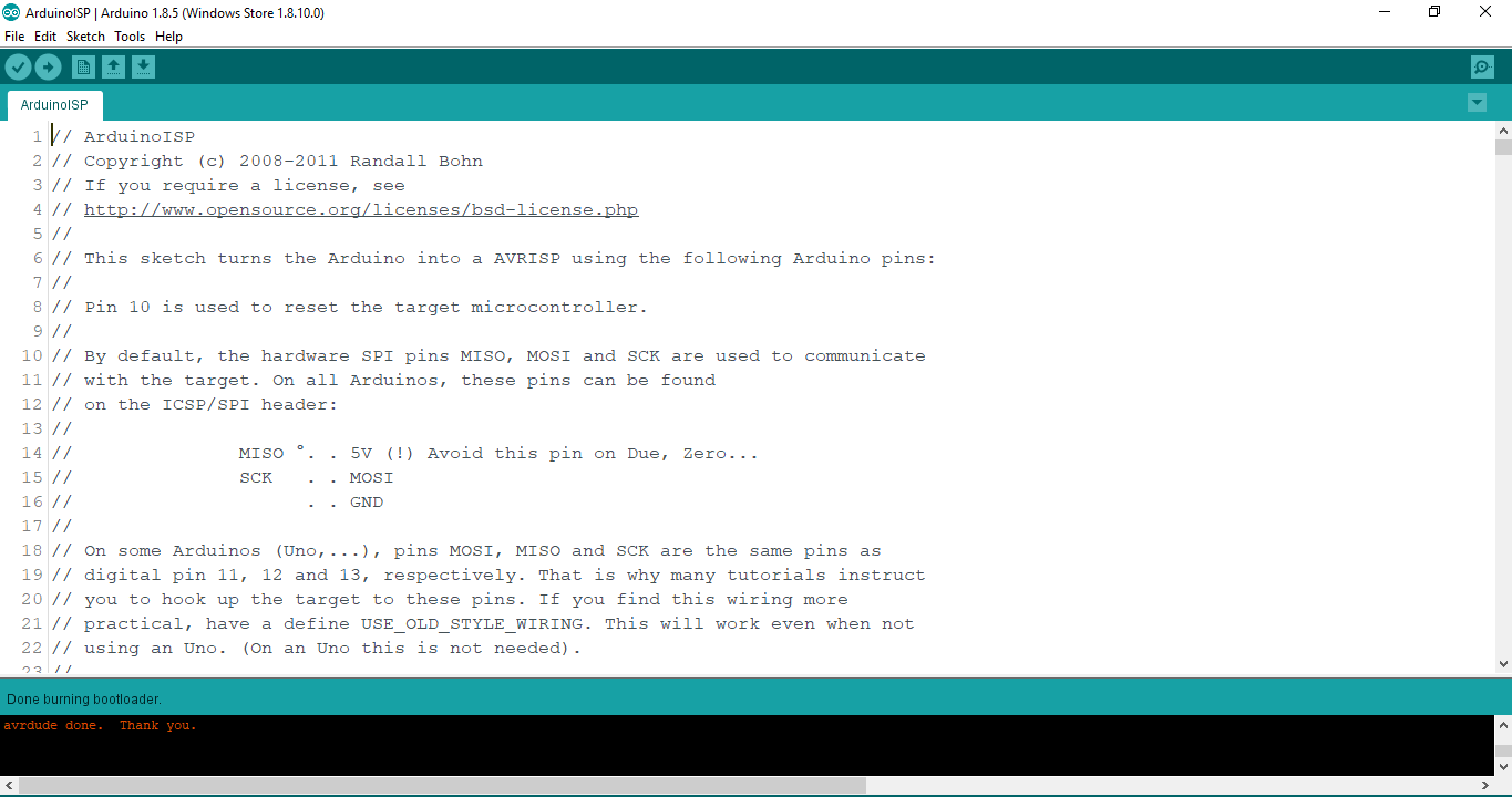
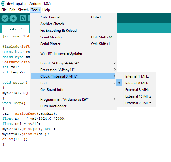
I was able to burn the boot loader at 1Mhz (internal crystal). Connected my board to arduino and try to run blink program.
After this I moved towards Temperature sensor program.
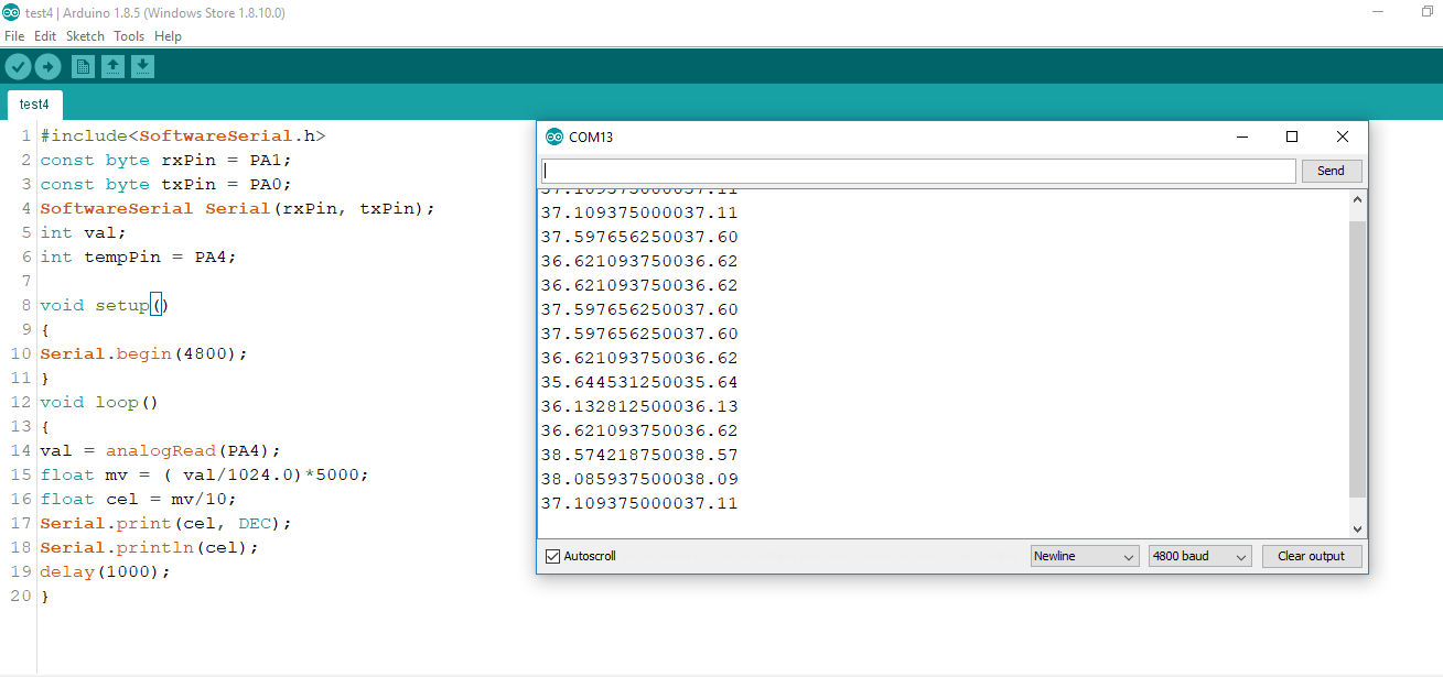
This is my code....
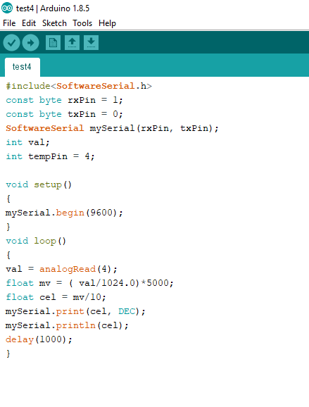
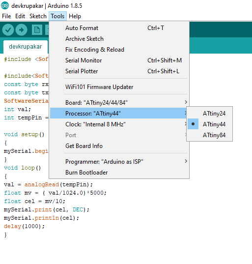
In this code I write the signal pin is pin 4 which is PA4 pin of the attiny 44A and 0,1 i.e PAO, PA1 of attiny44 are the tx and rx pins in the code. When the settings are done compile and upload the code. Go to tool option and select the serial monitor to Check the reading of temperature on serial monitor. You can also check the graphical representation of the readings by choosing serial plotter option.
After blinking I upload the sensor program, but I got error.
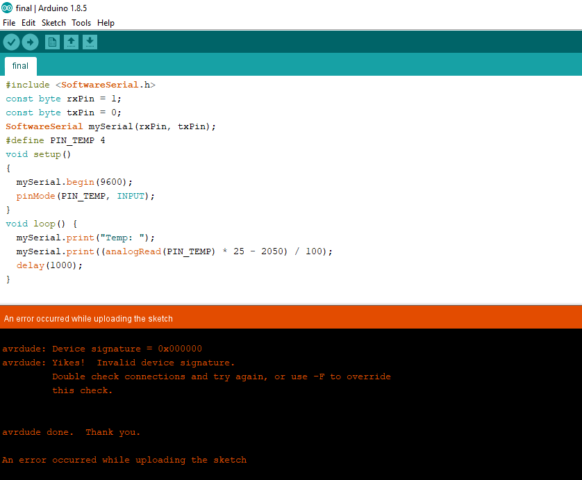
The error was the device signature error i.e firstly I have to check the connections.
I checked the connections but they are okay. So, I again repeat the same procedure. But I got the same error. This is frustrating stage because we are 3-4 people who are using LM35 in their project and everyone got same error.
As per my instructor maybe it is soldering issue. Then I checked the soldering of temperature sensor and repeated the same procedure. But again I got device signature error.
So, Me and my instructor decided to check the output or temperature reading by changing the clock and baud rate.
Again select the all things like board, clock ,etc.
Finally sensor shows the reading on the serial monitor.
Clock - internal 8Mhz and baud rate- 4800
And after few hours my temperature sensor shows some readings.
So, finally I did the sensing part of project. This is very important in my project because the water flow and air flow ON-OFF system is depend upon temperature.
Group Assignment:
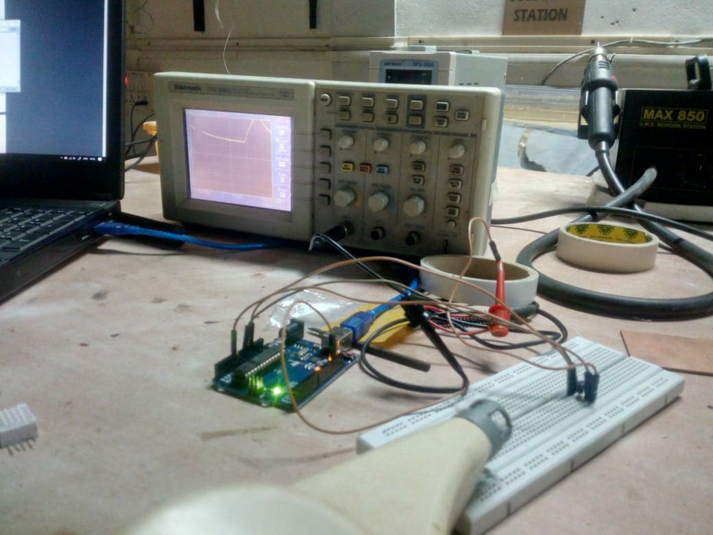
In group assignment we have to measure digital signals and analog level of an input device. We 3-4 people working on the temperature sensor i.e LM35 as a input device.
Here we check signals/output for our temperature sensor with the help of CRO, after adjusting the volts/div and increasing the time duration to around 2-10secs I was able to observe the output.
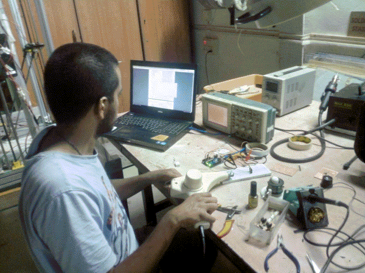
I used a heat gun to test the rise in temperature.
This will basically help me understand how I should write the code. My colleague Rohan help me to write the code.
You can download original board file from here.
You can download original PNG file from here.
You can download original code file from here.
Learning Outcomes-
In this assignment I learn about input device i.e temperature sensor. Initially I have fear about programming but rightnow, I learn how the output depend upon clock baud rate settings as well as port selection. So, this week is good and also important according to my project.