Rohan Rege
Fab Lab Zero
Vigyan Ashram
<- Home
This week were tasked with:
1: Model (draw, render, animate, simulate, ...) a possible final project, and post it on your class page with original 2D and 3D files.
2D/2.5D
I have very little experience with 2D softwares as I dont use them very much in my life. I always use 3D cad softwares as they have a 2d
component too. Hence softwares like inkscape, gimp, photoshop are quite new to me. In the lecture I came to know that there are actually
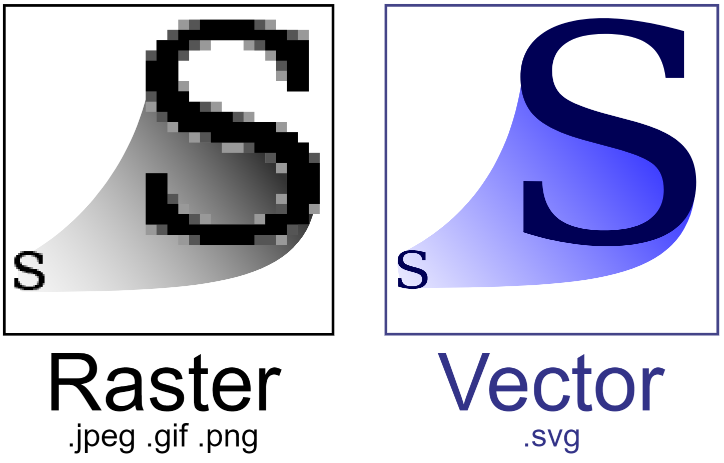
two types of 2D softwares raster (pixel based) and vector (curve, math based). In simple terms vectors are source files and rasters are
output files.
You can easily understand the difference from the image below.
I decided to try Audtodesk Sketchbook, I had some previous experience of using it as it was pre installed on my Samsung Note II. Sketchbook
is now also availble for windows and can be installed easily from the store or autodesk website.
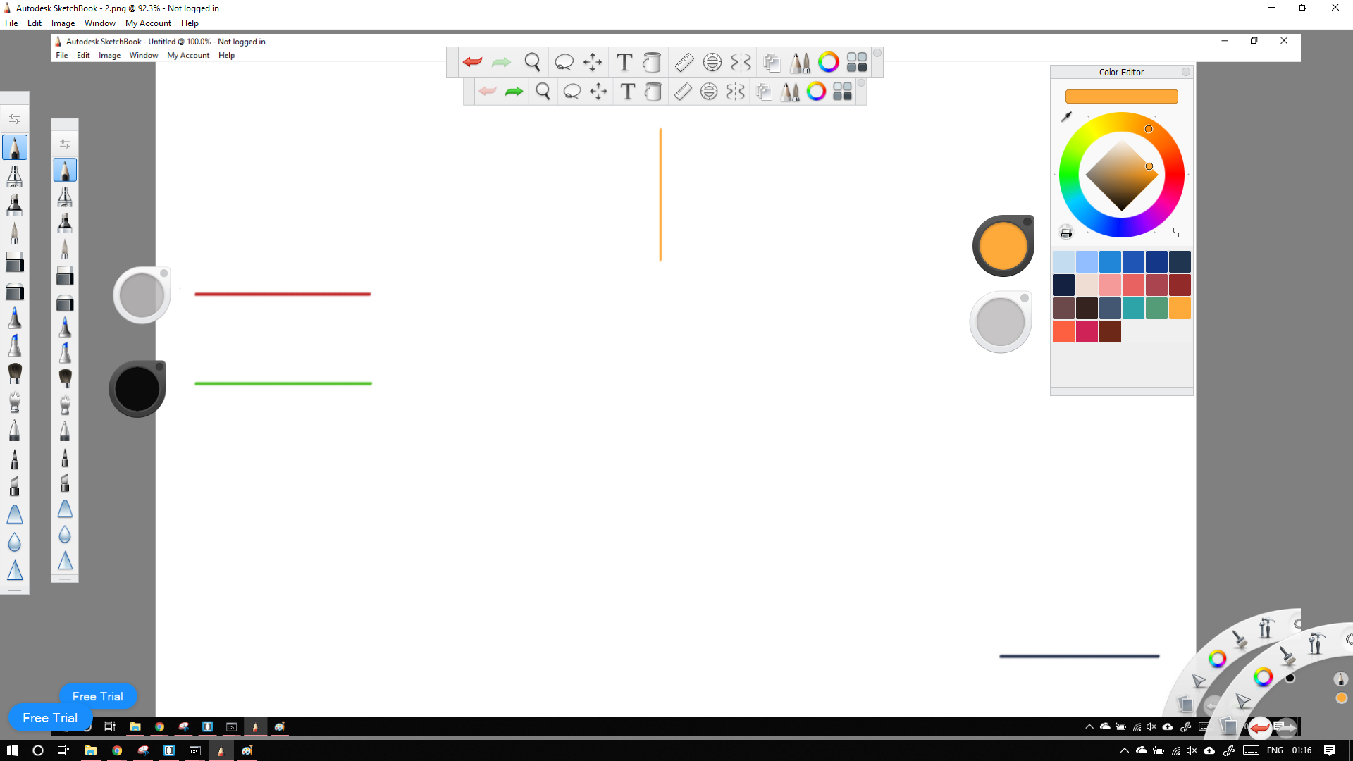
The transparent pluck (white) is one with red line next to it.Color pikcer is below it with green line nect to it.
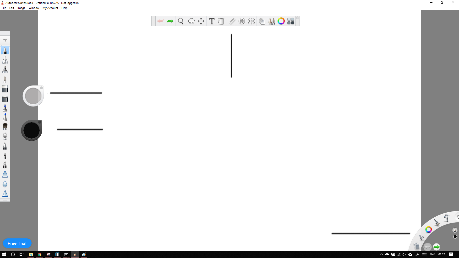
The basic UI of sketchbook consists of Brush pluck, Color Pluck, Toolbar, Lagoon and brush palette , etc. There are many more but in most
cases by default only these are tured on. Sketching in Sketchbook is very simple. Just select the tool you want and start sketching.
One of the features i like about sketchup is that it can apply colors with differnt intensity. I have created a simple cross pattern.
As you can see the go in increasing value of intensity (this could be similar to opacity option in other softwares)
Straight lines were drawn by holding shft and drawing lines.
Although very easy, It can be use for random doodles taking notes, It felt very basic. It feels like using an gloried version of paint.
I wanted something much more powerful.
Photoshop is one of the most powerful tools availble. The next best (free) alternative is GIMP. GIMP stands for GNU Image Manipulation
Program. GIMP is now available for other systems like windows.
I have done a simple comparison between GIMP and Photoshop. Being an hobbist (amateur) photographer I like to take BW shots. I dont
have a dedicated BW camera/lens in my setup. hence I use lightroom, but desauration of images can also be done in Photoshop and GIMP.
Heres how:
Both Photoshop and GIMP support double click and drag to import image. I simply double clicked the canves to import a PNG
I downloaded from the internet.

There are many ways to achieve BW like adding presets, using channel mixer etc. I am going with Desaurate command as it is the easiest and fastest way.
Steps for GIMP
In the toolbars select colors > Desaturate
Steps for Photoshop:
In toolbars select Image > Adjustments > Desaturate

Funnily enough I expected photoshop to give me options for selecting the type of desaturation required like GIMP.

To obtain the orignal and BW image click here
3D
In this assignment I have worked on 4 3D softwares
1: Solidworks
2: Fusion 360
3: Onshape
5: Antimony
Being a mechanical engineer, I hav the basic understanding og how various CAD softwares work.
We were taught CATIA in college, but I prefer Solidworks and use it extensively in my projects.
In fab academy I plan to evalute the softwares to see which one works best for me.
To do this I plan to make a simple cresent moon shape (by subtracting two circles) and then go few steps back and then intersect the circles to create a new shape.
Solidworks 2017
I maybe be partial to solidworks because I have been using it exclusively for 3 years now. I may also have been habituated to it.
Press Ctrl + N and double click the part icon


To start sketching in the upper right menu select sketch and the sketch icon. Then select a plane by clicking any rectangle in the display. Each rectangle represents a plane.
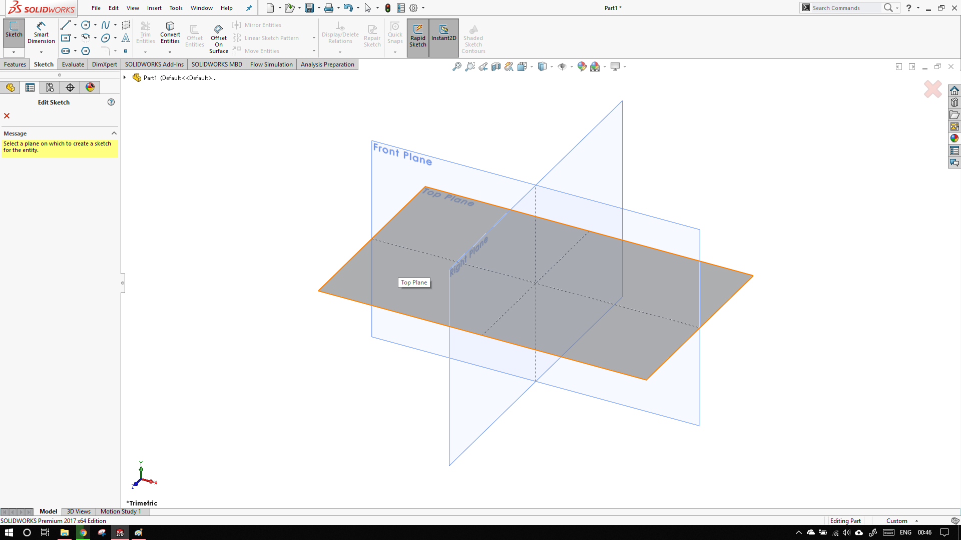
Solidworks will automatically make our view normal to the sketch plane. The current sketch plane can be determined by the looking at the orientation of the axes at the bottom left.
Now click and hold the right mouse button and slide to the right. You will be greeted mouse gesture wheel. Select the circle option.
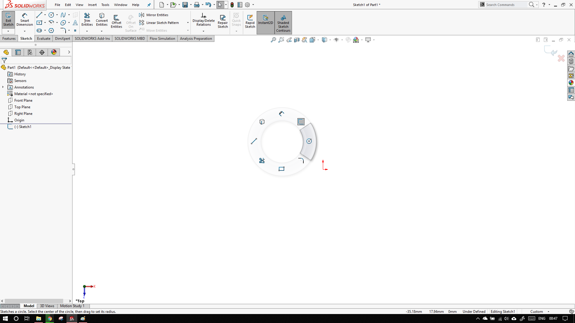
On the left panel, circle option will open. In the circle you can see there are two types.
Centre cirle
3 point circle
In the icon, the points are labeled 1 2 3 ... these determine the order of which to draw the sketch. So in this case, first we draw the centre and then the outer edge.
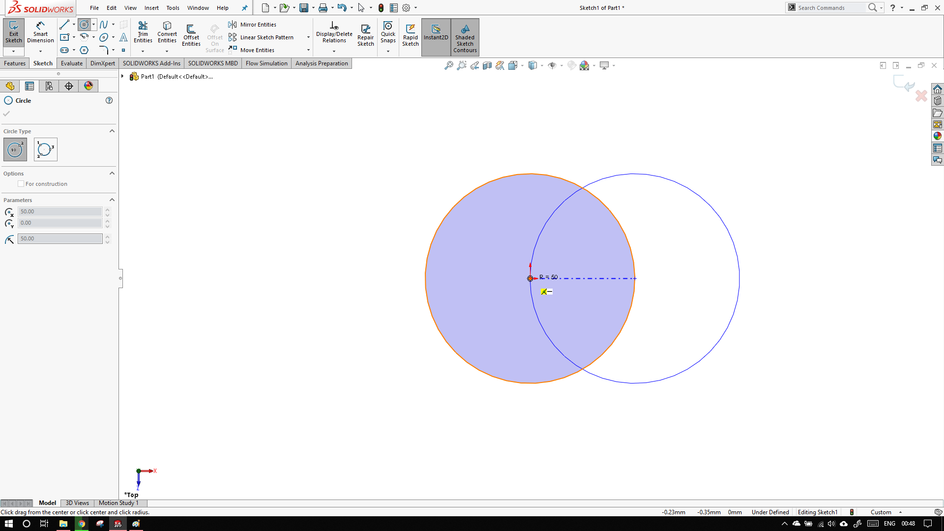
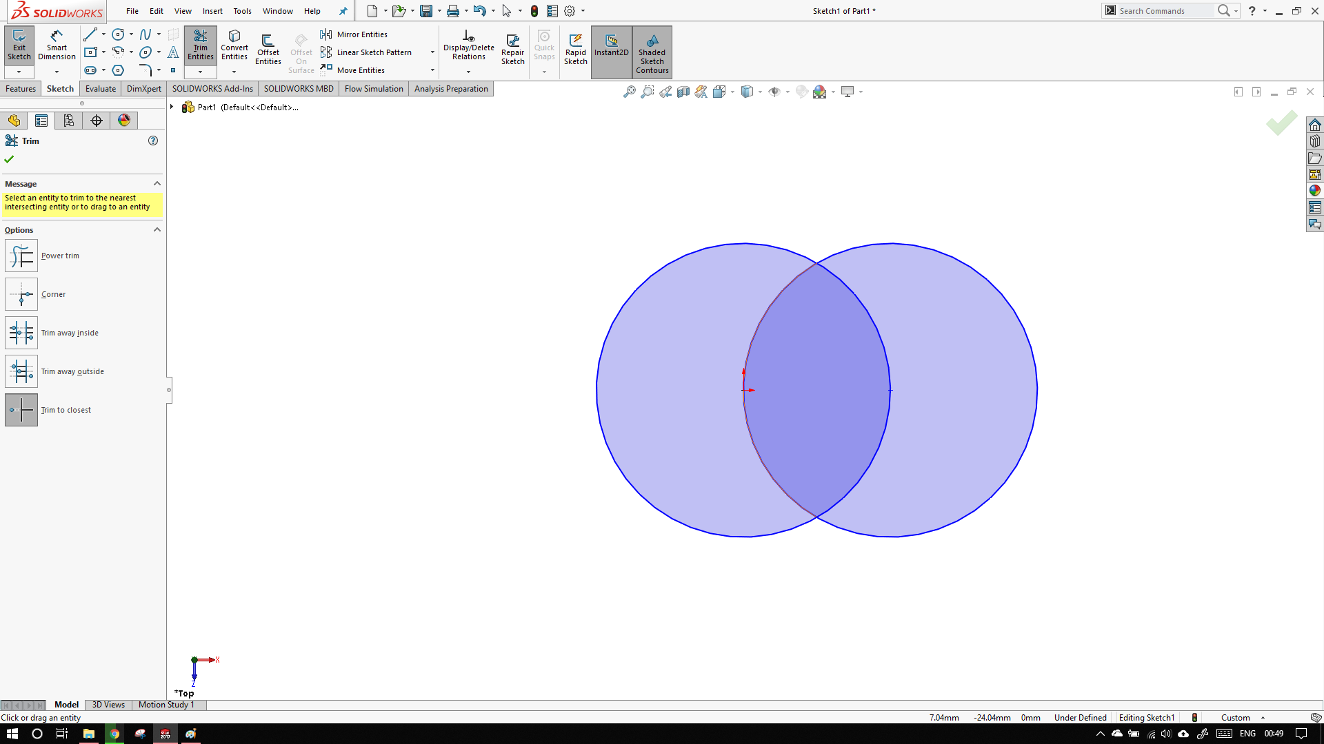
Draw two circles, one on the origin and other one on the circumference of the other. With equal radii. Click the little green tick when done.
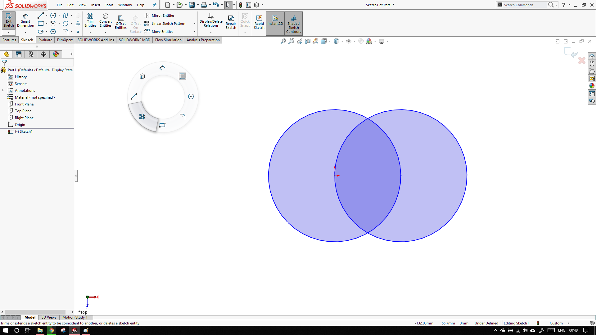
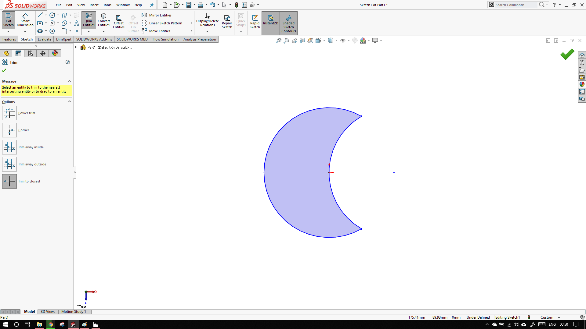
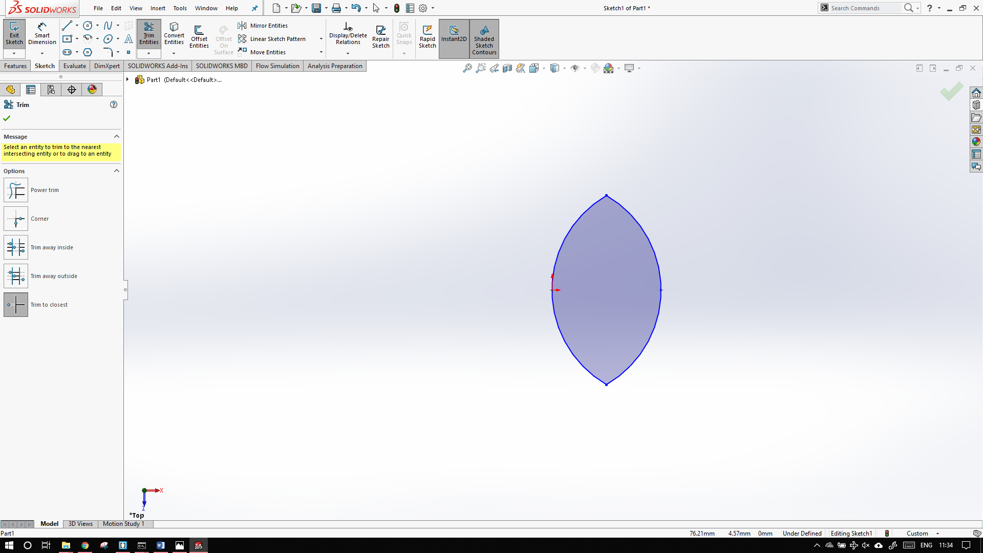
Now to trim, again use the mouse gesture and slide to the bottom left and select the scissor like option. Select the 'trim to the cloest option' and trim the edges as shown.Now press exit sketch
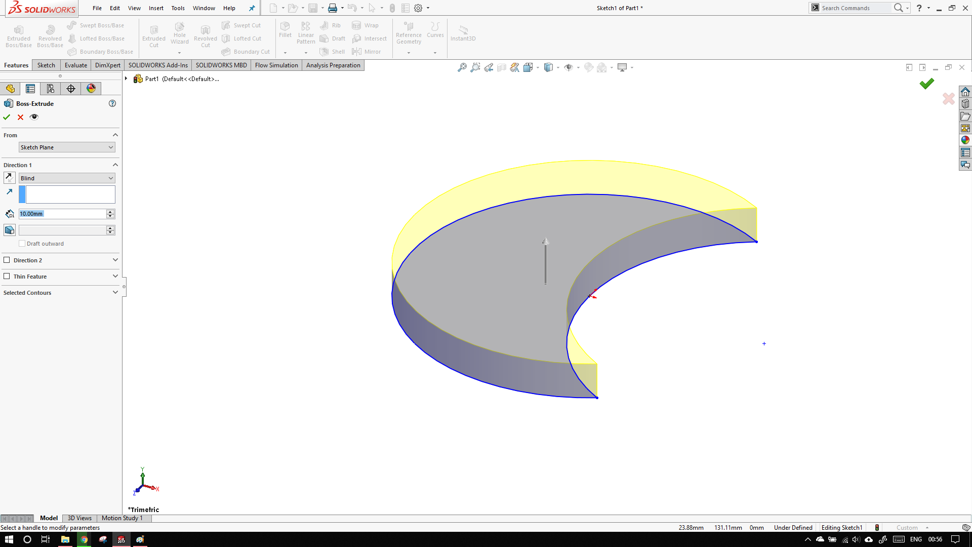
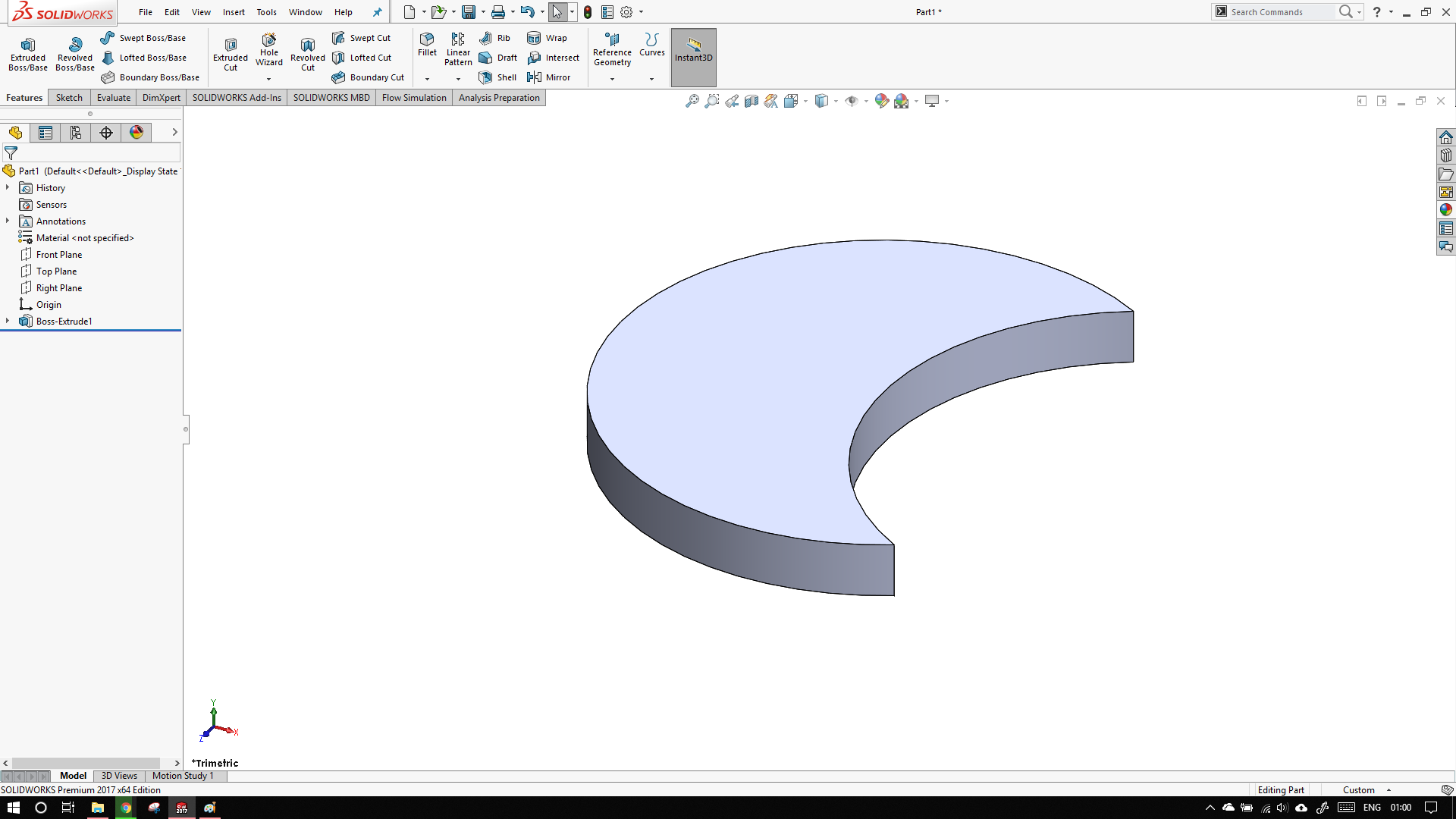
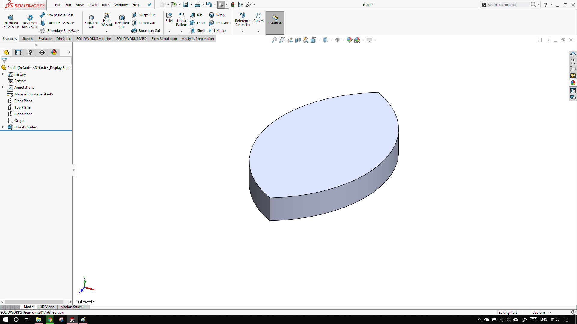
Now click the features tab and click extrude. Select and extrusion of 10mm and click the little green tick
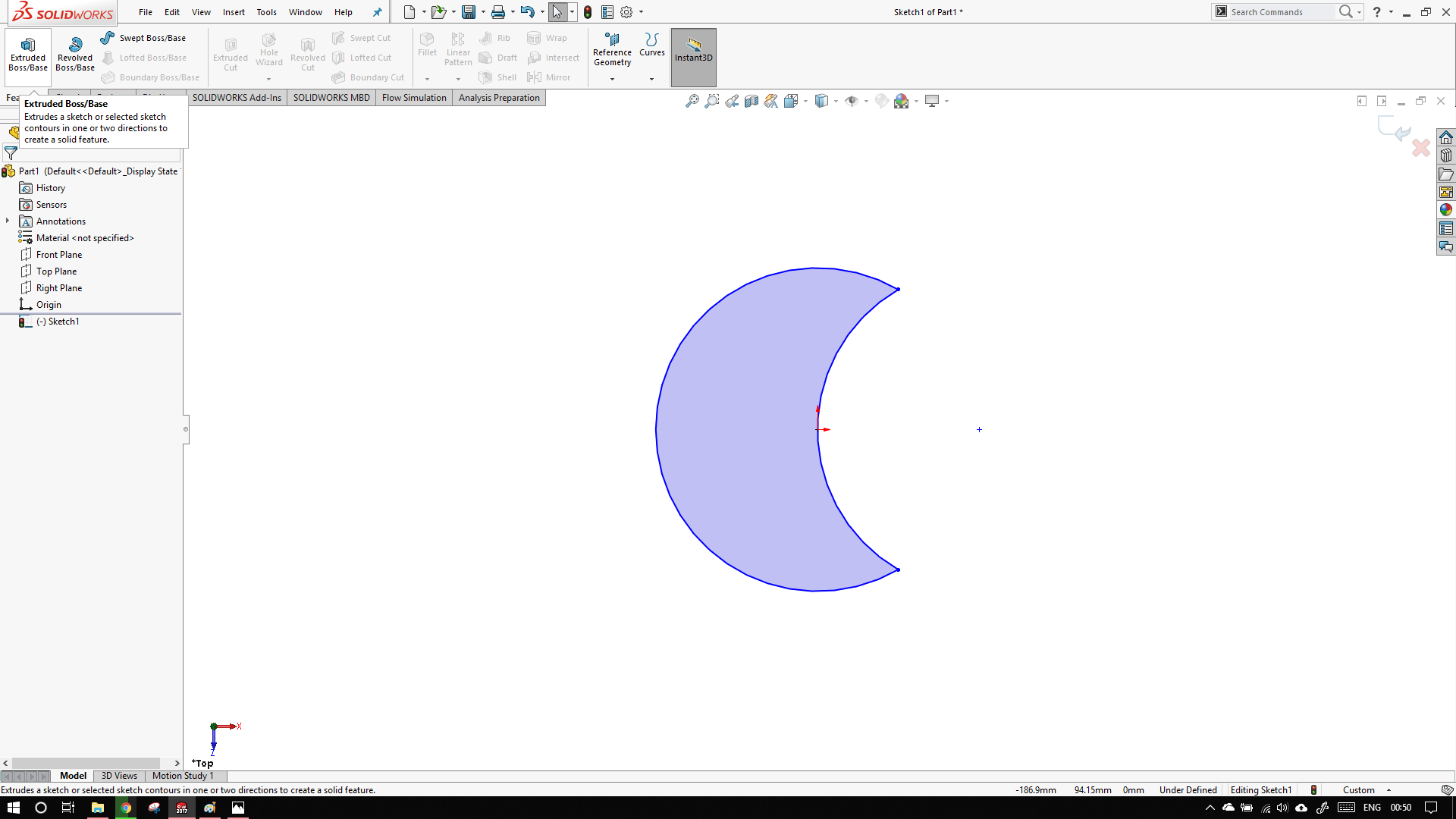
Now, press Ctrl + Z until you reach
and then trim as shown:
There maybe a better way than pressing undo multiple times that I do not know of. If you know a better way please tell me.
The solidworks file can be downloaded here
Fusion 360
I have not used fusion before this. I do not know any hotkeys so my way of doing things are highly inefficent.
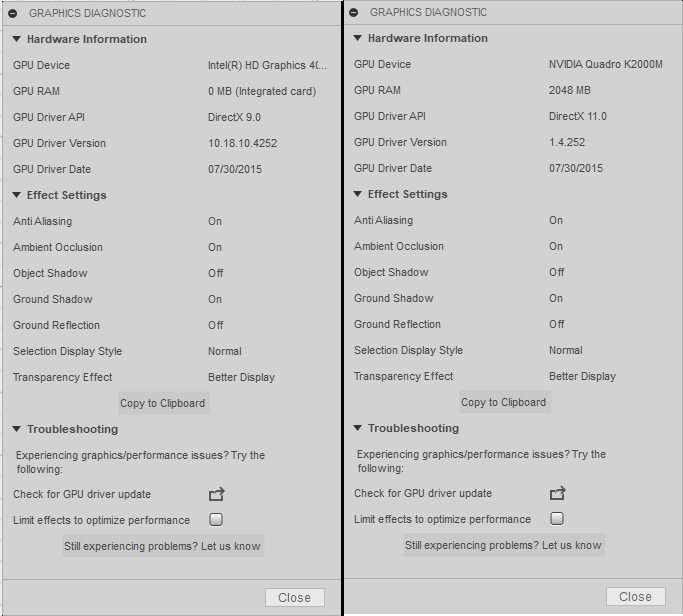
First thing I noticed when Working with fusion was that the program was extremely slow. Now I have a decent machine with i7,8Gb,2Gb Nvidia and 250Gb ssd. After running the graphics diagnostics I found that fusion was running on internal GPU rather than dedicated GPU. This can be easily solved by selecting the 'Run with graphics processor'.
After restarting with dedicated graphics, the user interface is somewhat similar to solidworks.
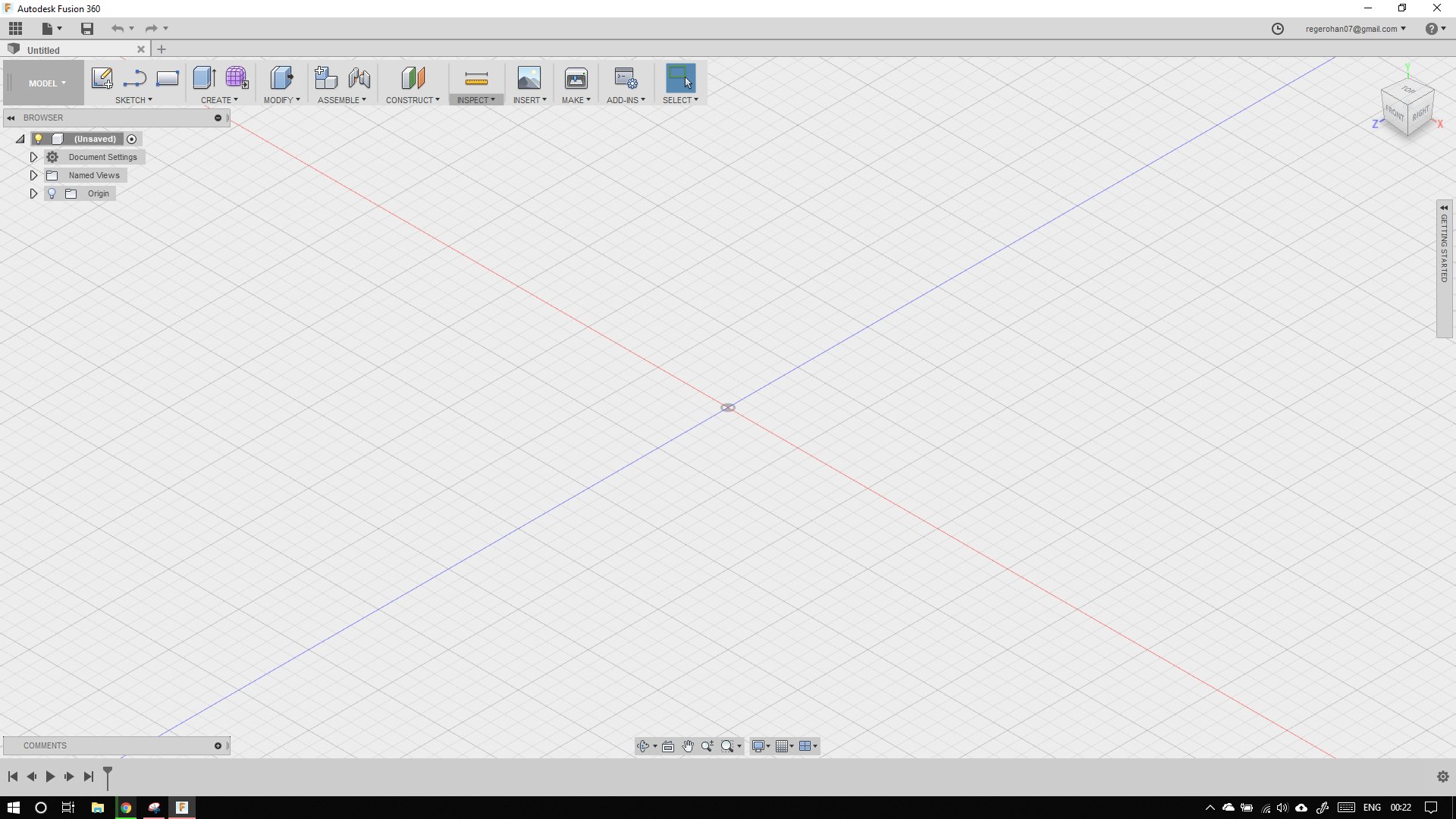
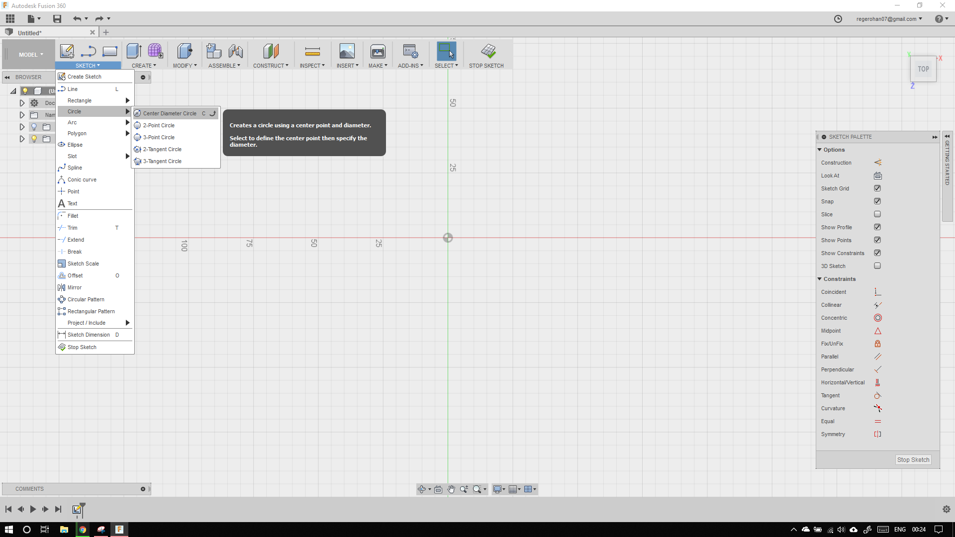
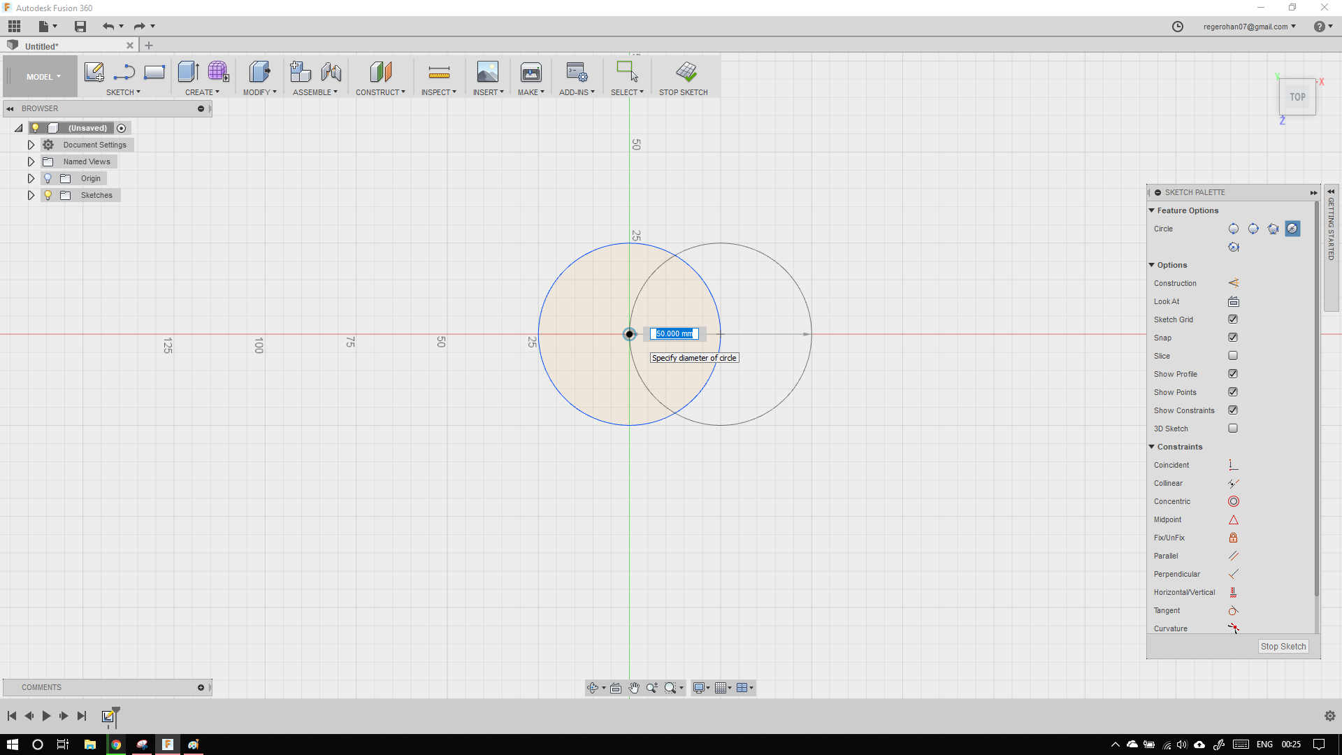
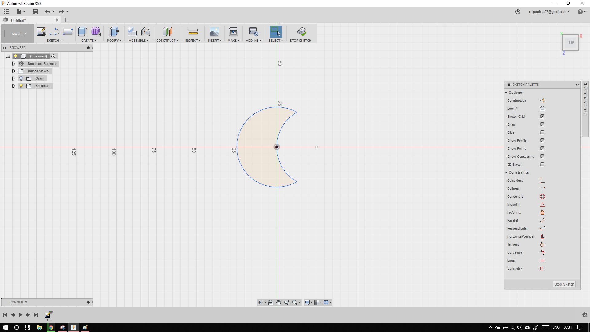
To being a new sketch, click the sketch drop down menu, go to circle -> centre diameter circle. Then draw two circles as shown below. I also got to know that the hotkey to draw a circle is 'C'
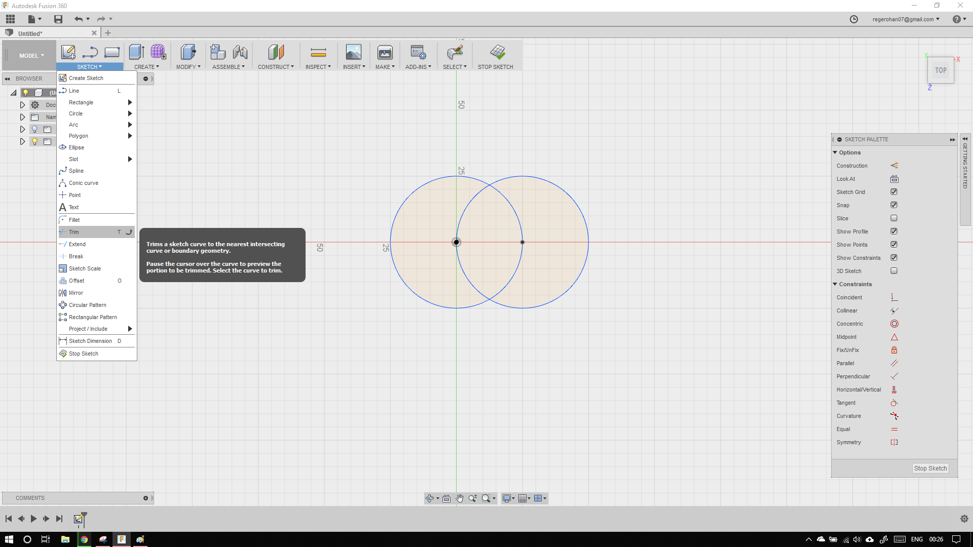
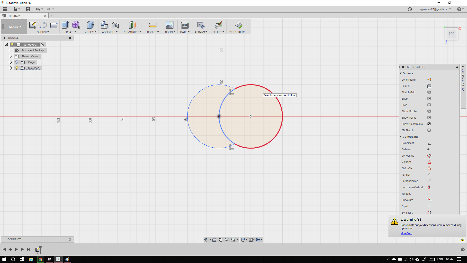
Now to trim, again go the the drop down menu, and scroll down to trim. The hotkey to trim is 'T'
Then trim the arcs as shown.
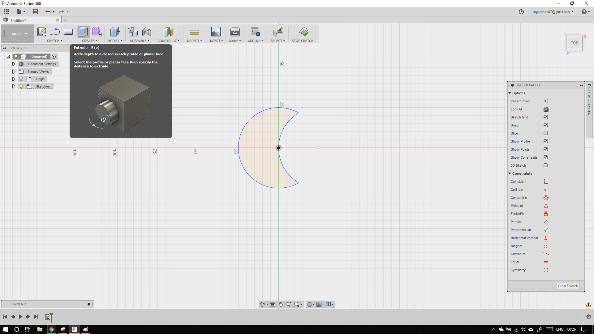
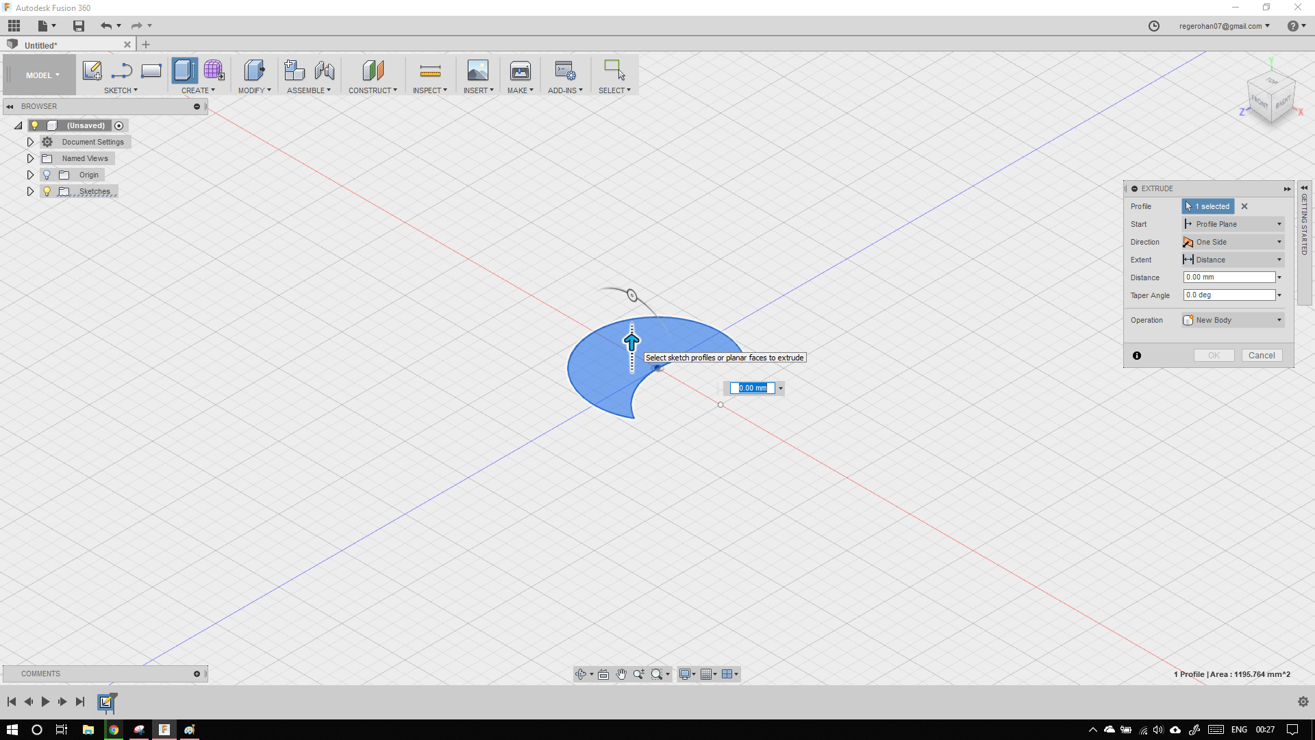
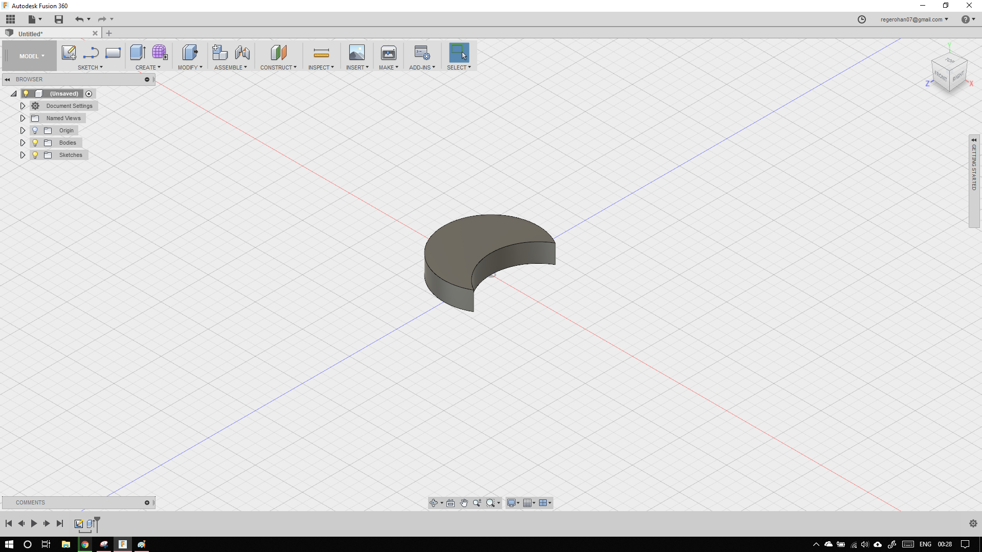
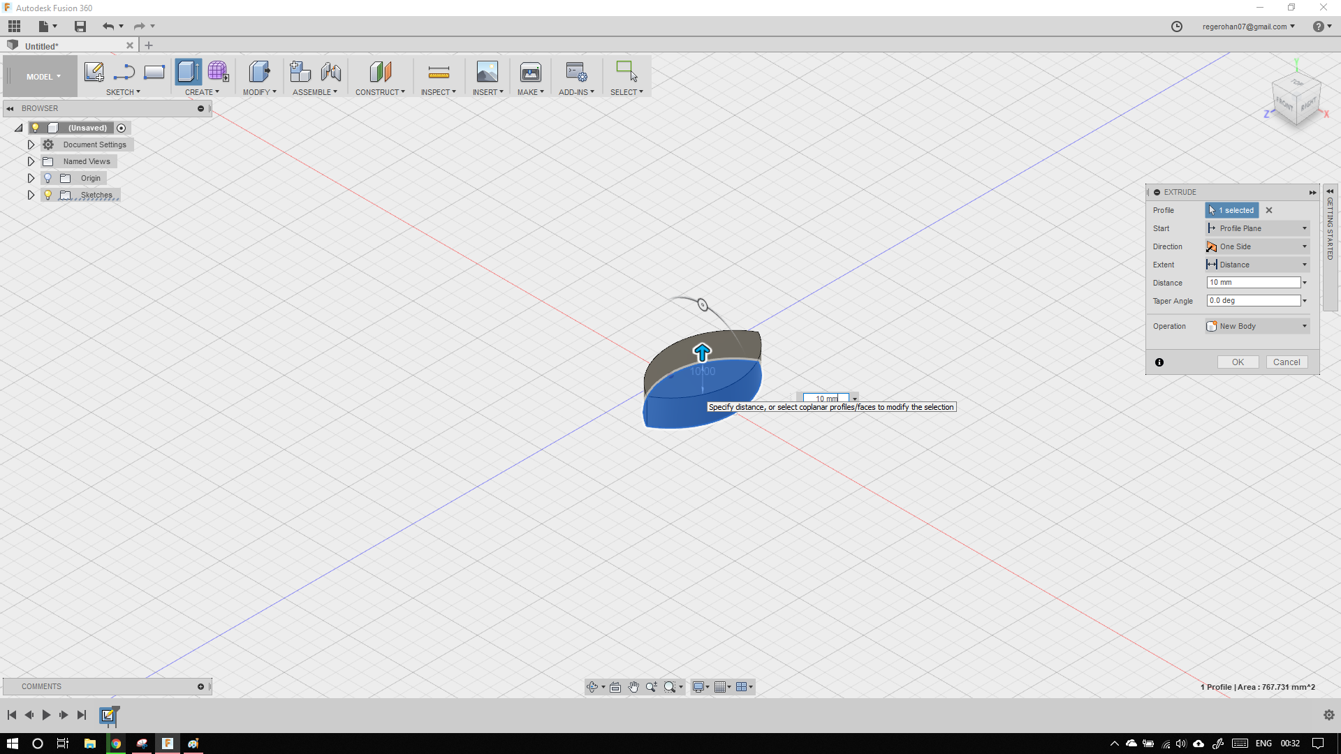
To extrude click the create button, or the press the 'e' (hotkey)
Select the sketch to profile to extrude, by clicking the sketch, and extrude by 10mm
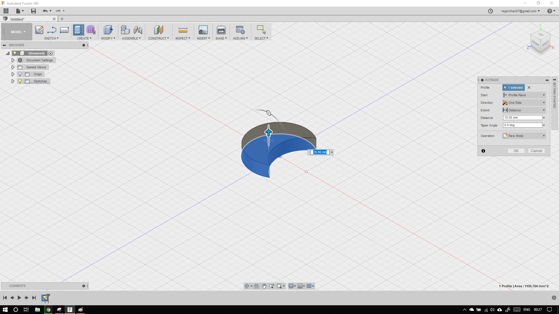
The final output model should look like this.
Now repeat the same steps like solidworks, and undo multile times to obtain the required wing like shape.
here also I could not find a better way to change from subtraction to intersection, without undoing and trimming.
If anyone knows, please tell me.
One additional feature I would like to mention is that, fusion 360 is partially cloud based, program. This has its advantages and disadvantages. I can recover all my files by logining into fusion on any PC. All the heavy lifting can be uploaded to cloud. This is really useful on low spec laptops. Also Fusion has some kind of versioning system. similar to git.
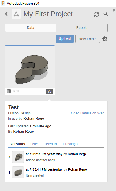
The CAD file can be downloaded here
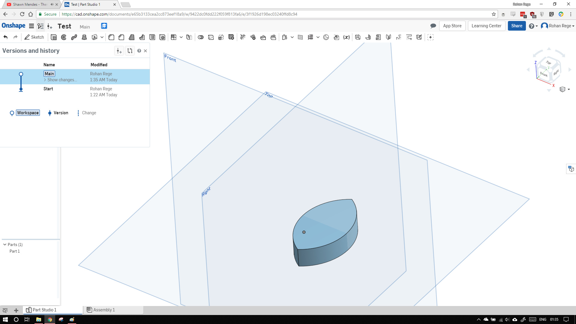
Onshape
I never knew browser based CAD existed bedore this. I have had tried the online (chrome extension) of AUTOCAD before in early 2013-14, but it was barebones and didn't work as well as the offline counterpart. I decided to give it a chance again. Going through the website it looked promising. The UI of Onshape looked like a mixture of solidworks and fusion 360. It is a completely cloud based CAD. So it can be used on any platform we a decent and supported web browser. Onshape works even on mobile.
To setup Onshape I first changed the units to the correct system (SI) and set the view manipulatoin to Solidworks (maybe the reason my UI looks like Solidworks)


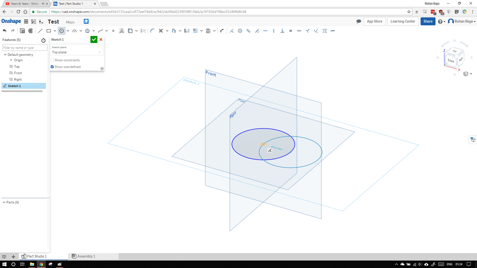
To start a sketching, select the sketch icon and select anyone plane, I have selected top plane.
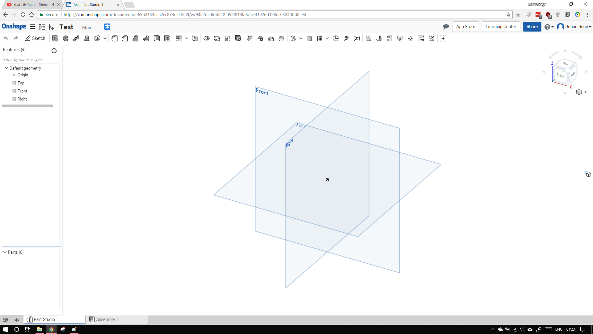
It is annoying that Onshape doesnt make the view normal to the sketch automatically.
Select the circle tool and draw two circles like before.
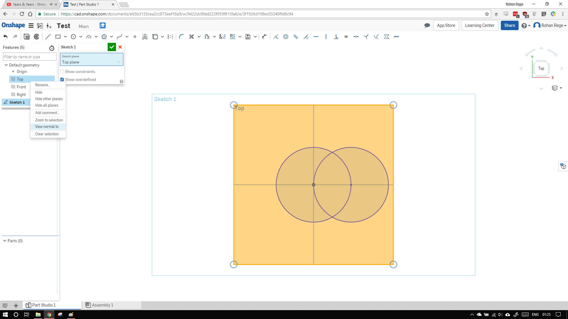
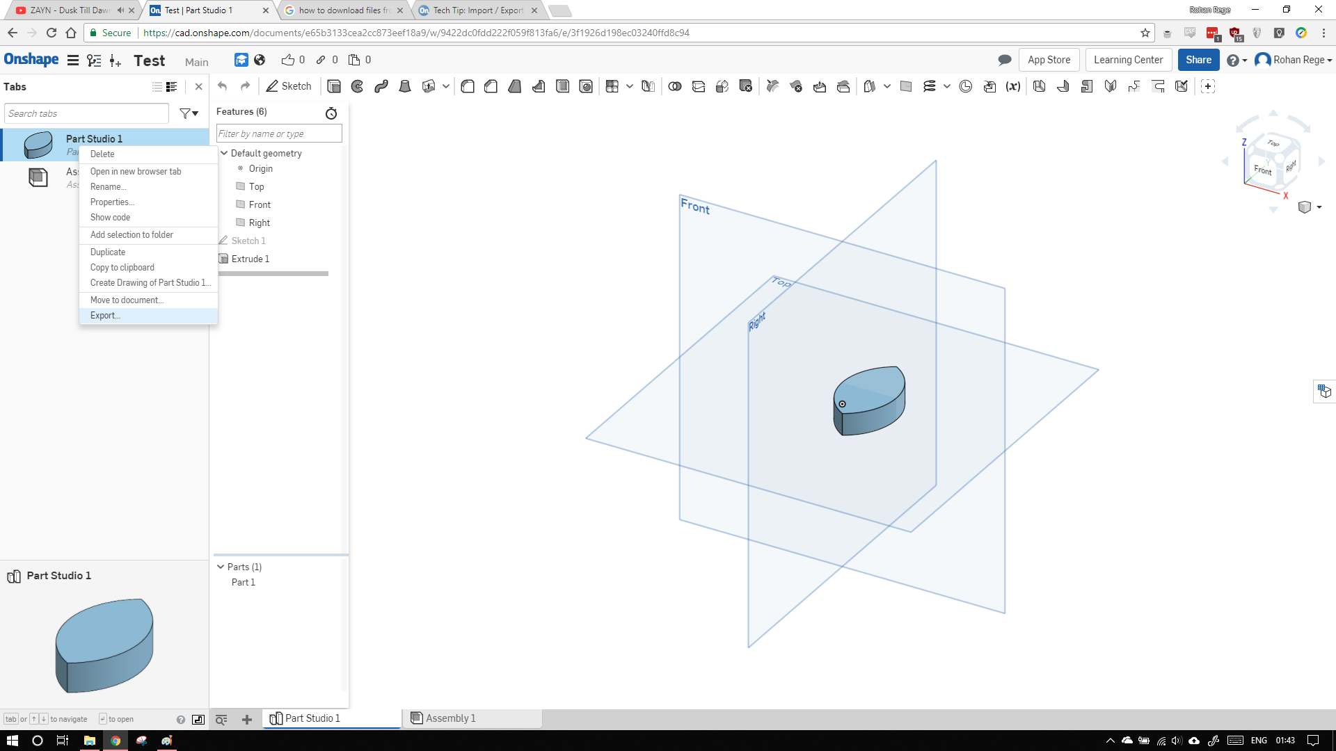
To make the view normal to a plane, select the plane -> right click -> view normal to
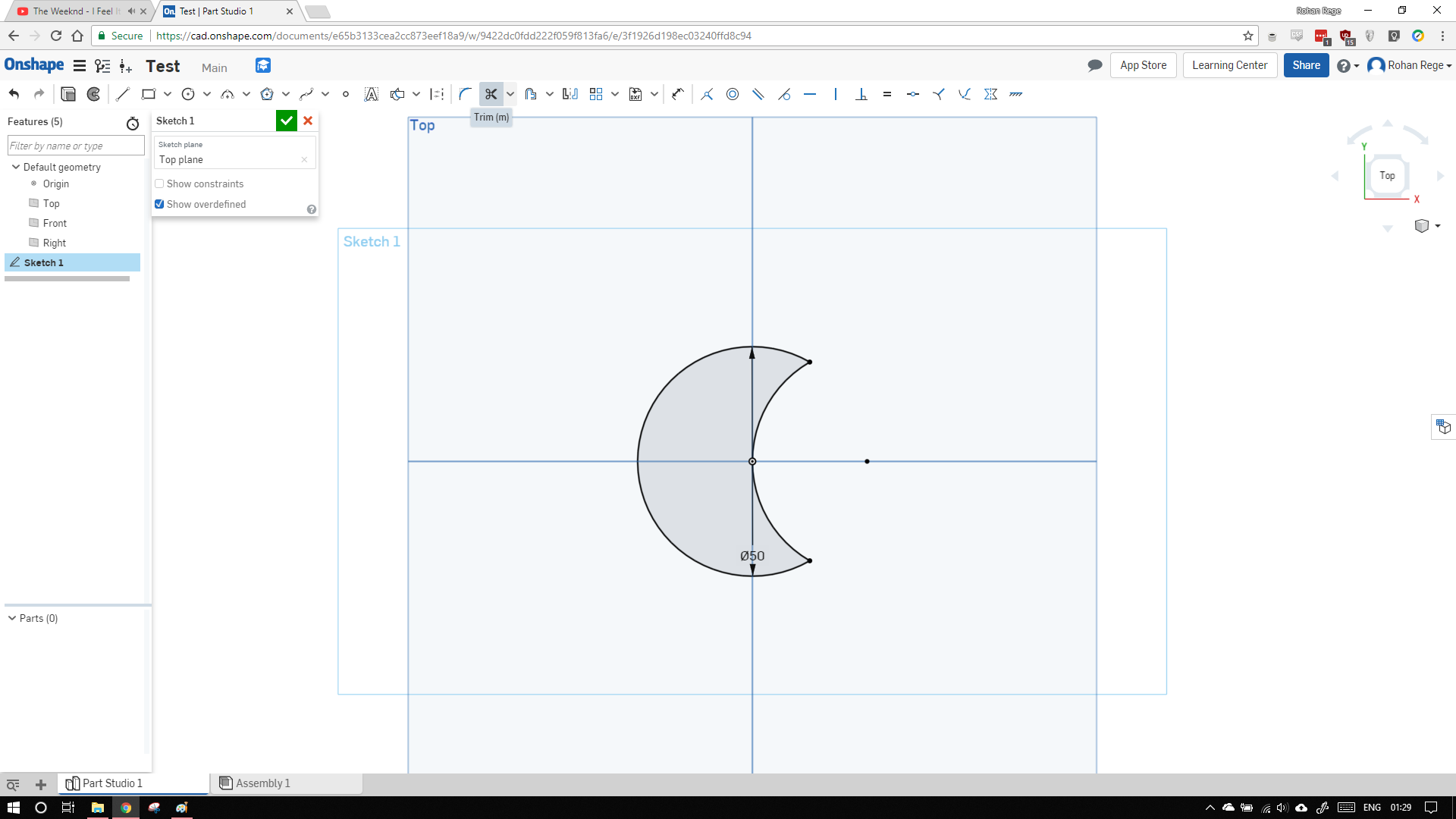
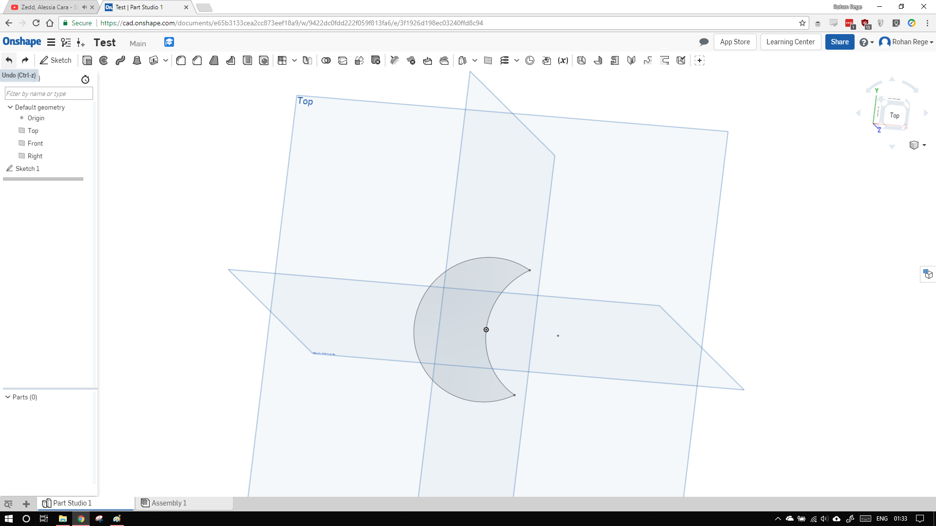
Use the trim tool to trim the circle as shown, the hotkey for trim tool is 'm'
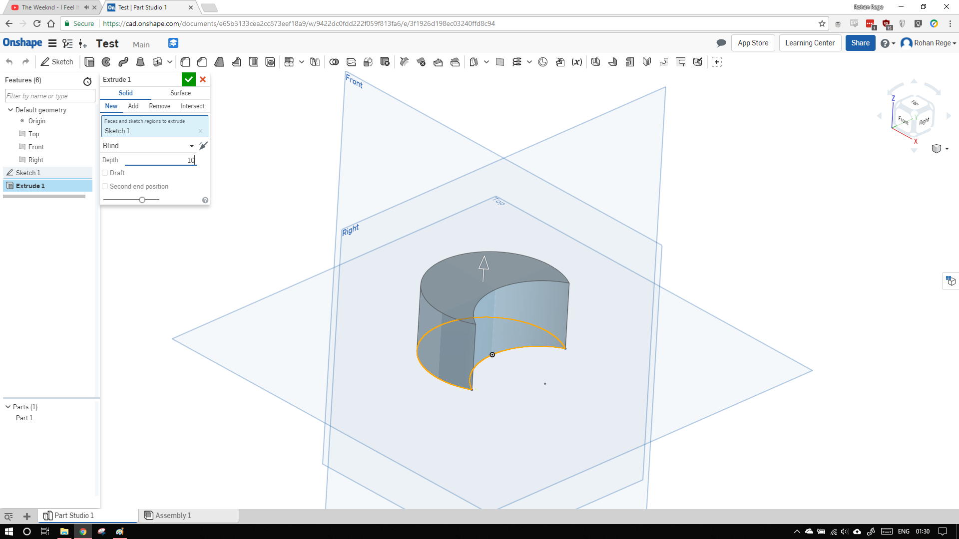
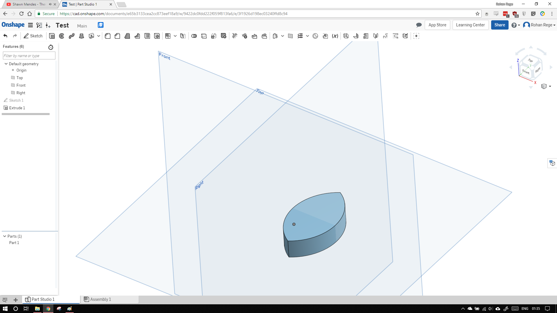
To extrude use the extrude command and then set depth of 10mm and select the green arrow.
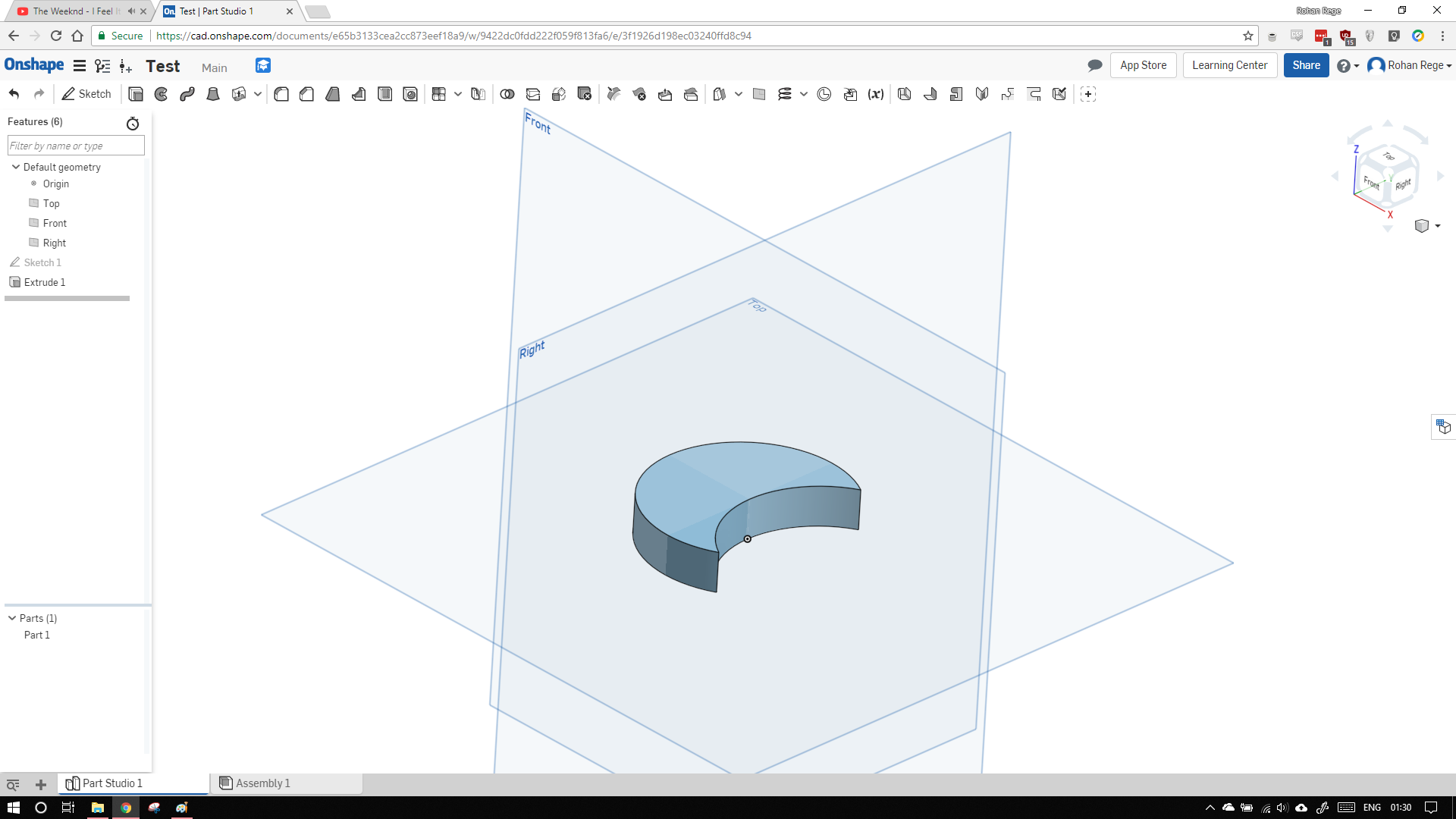
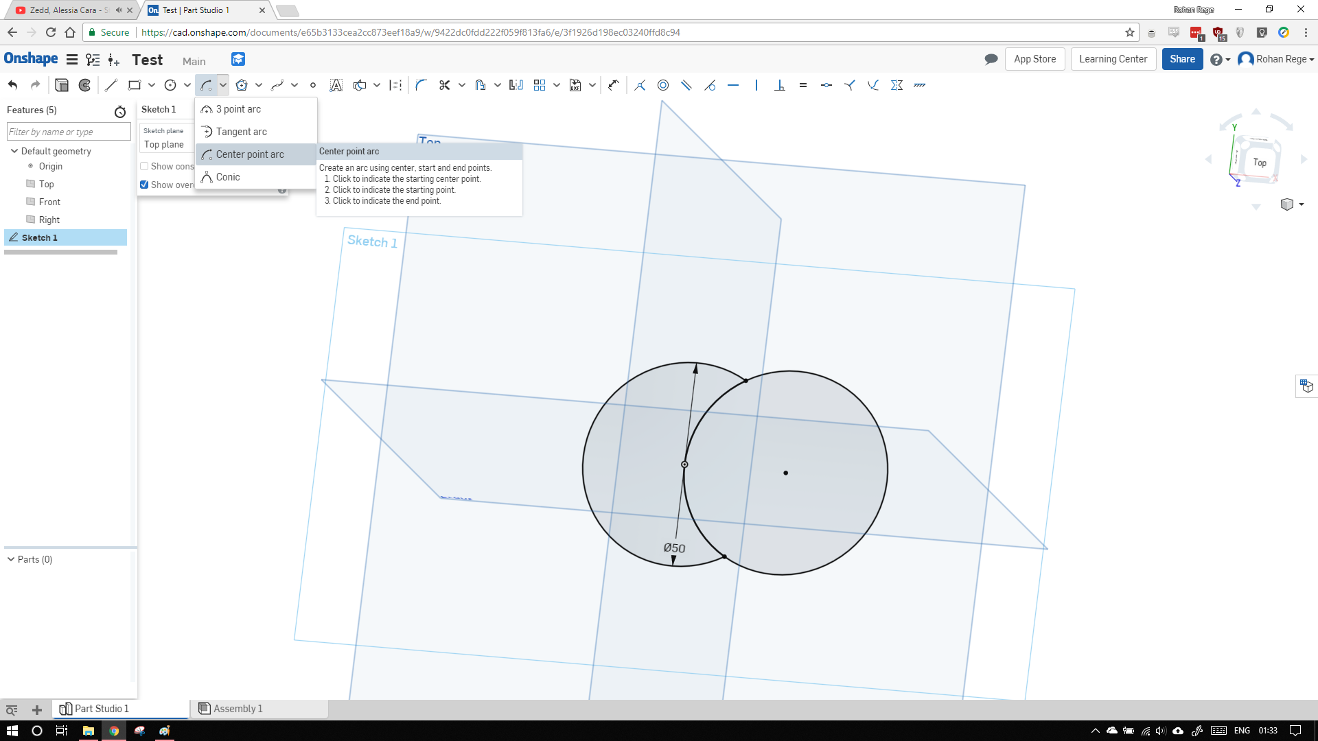
Onshape has limited number of undos so I couldn't go back beyond 2-3 steps. So to now make our teardrop shape, I drew an arc.
To draw an arc, select the arc button and click on centre point arc. Select the centre and as origin and draw the arc as shown.
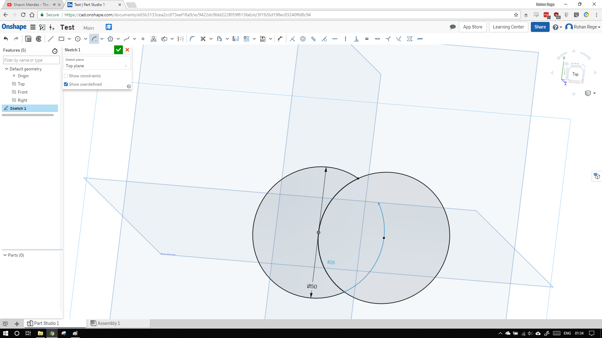
Now extrude the shape again to obtain the teardrop like shape.
I encountered a problem I could not easily find anyway to export the document from cloud to PC.
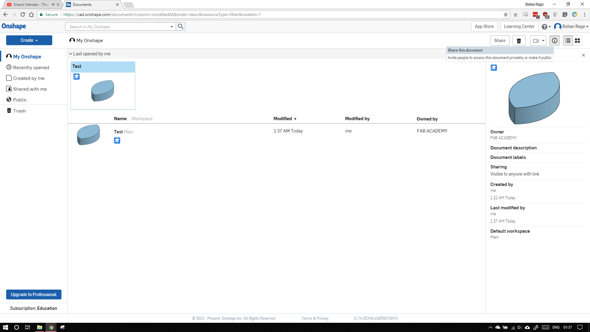
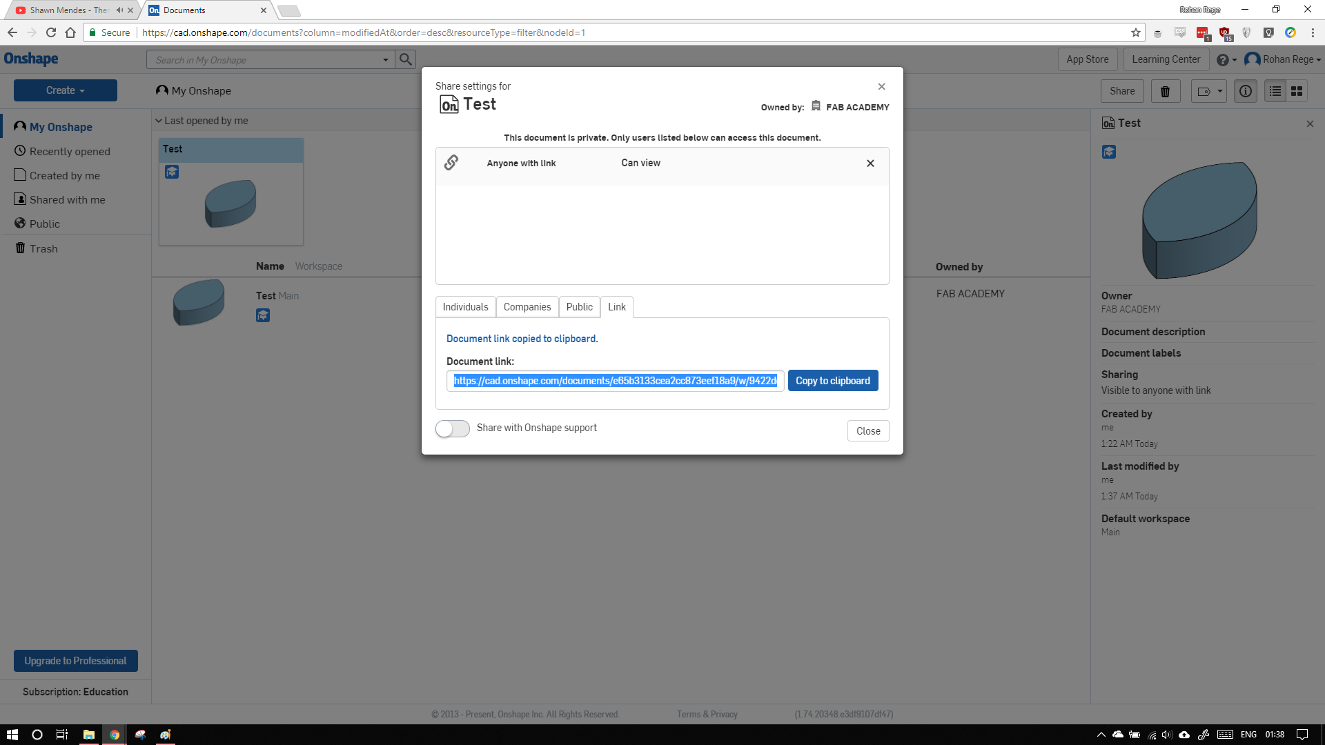
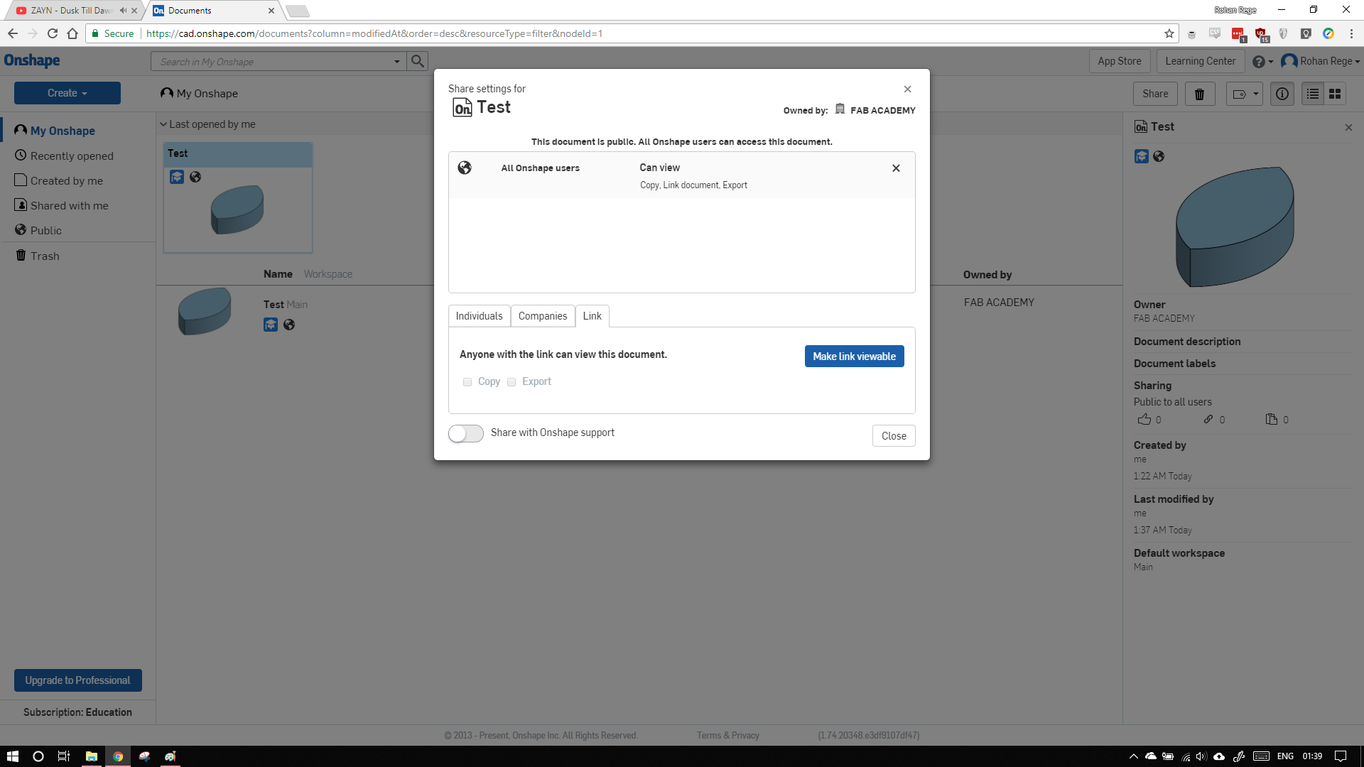
After looking through google, I found a few pages for my stupid question but I could not find the buttons mentioned on the webpage in my Onshape UI.
Maybe they have upadated the UI
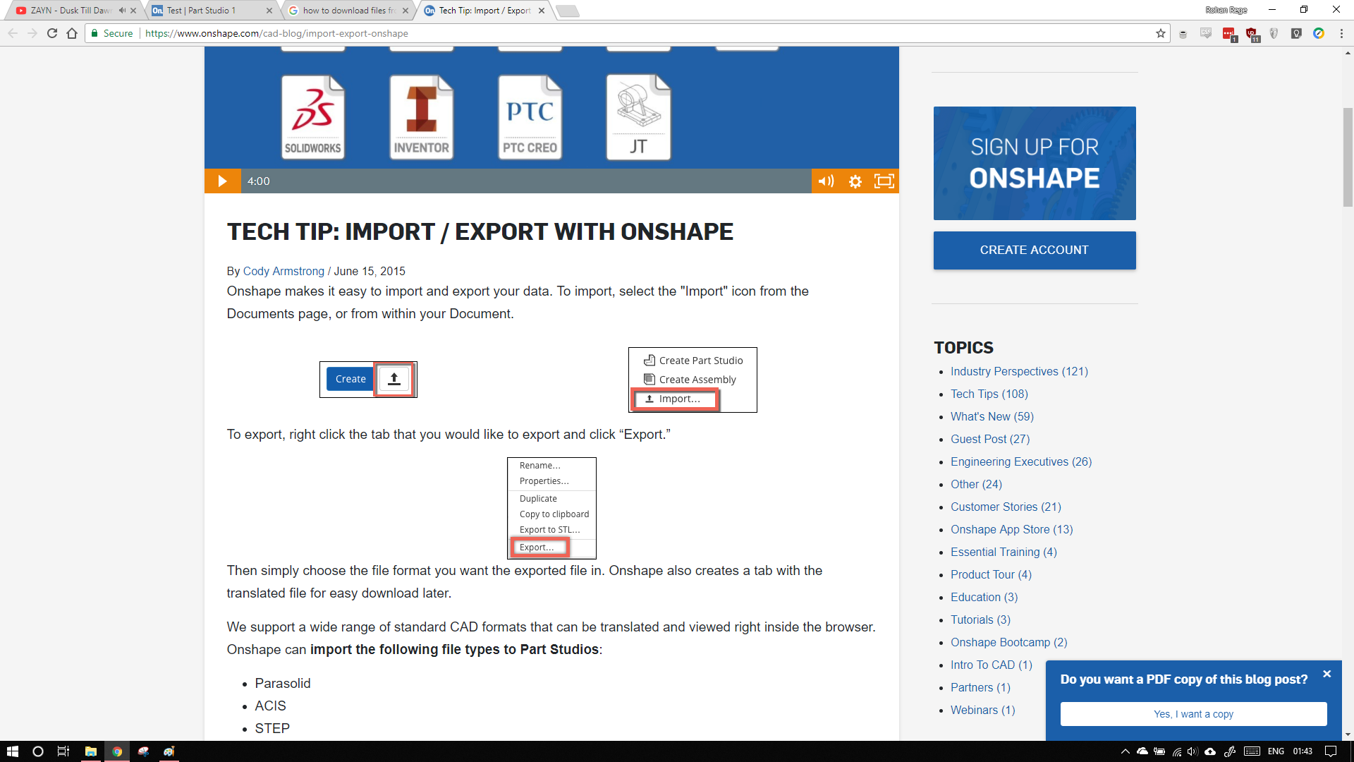
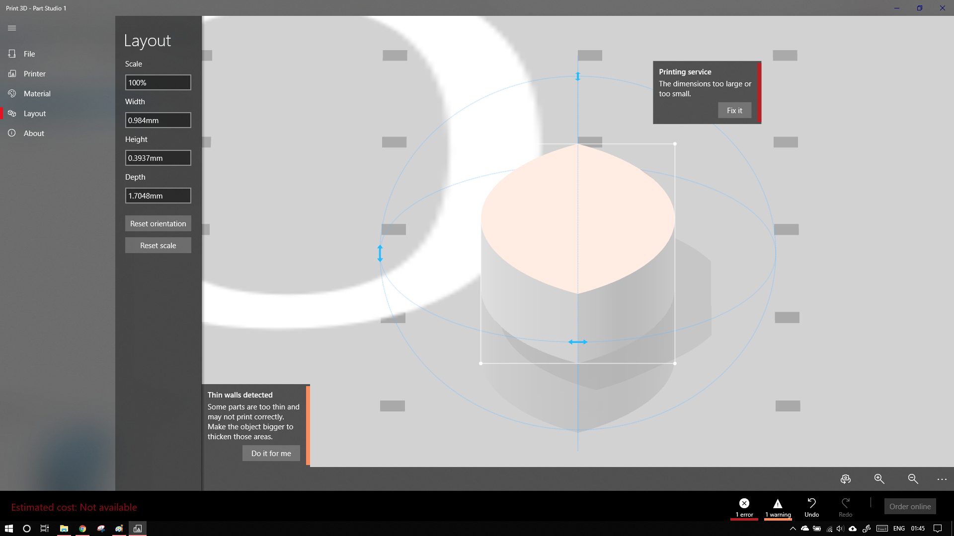
After going throught the webpage again, I found the export button. I then exported the file in STL in 'mm' but when I opened in windows, there was some problem with the units.
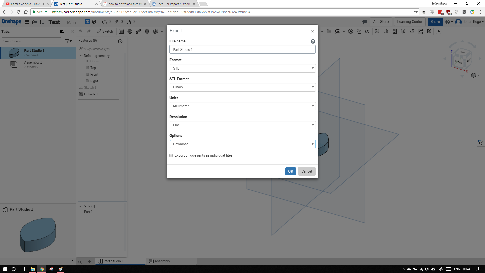
s
Due looking around for the export option, I also came to know that Onshape also has a versioning system similar to that of Git.
The CAD file can be downloaded here
Antimony
I went with Antimony. Antimony is quite different than other cad software. In traditional softwares like Solidworks, Fusion, CATIA you have to sketch parts/bodies on the plane. Further modifications to this body/solid/part can be done by extruding/cutting. Antimony give you a different apparoach, All the sketching is done with help of primitives.
Installing antimony is bit different than others. Currently is it available as a prebuilt (for Mac). We need to compile it in order to use it in Ubuntu. To do it, do as follows
sudo apt install git build-essential libpng-dev python3-dev libboost-all-dev libgl1-mesa-dev lemon flex qt5-default ninja-build cmake
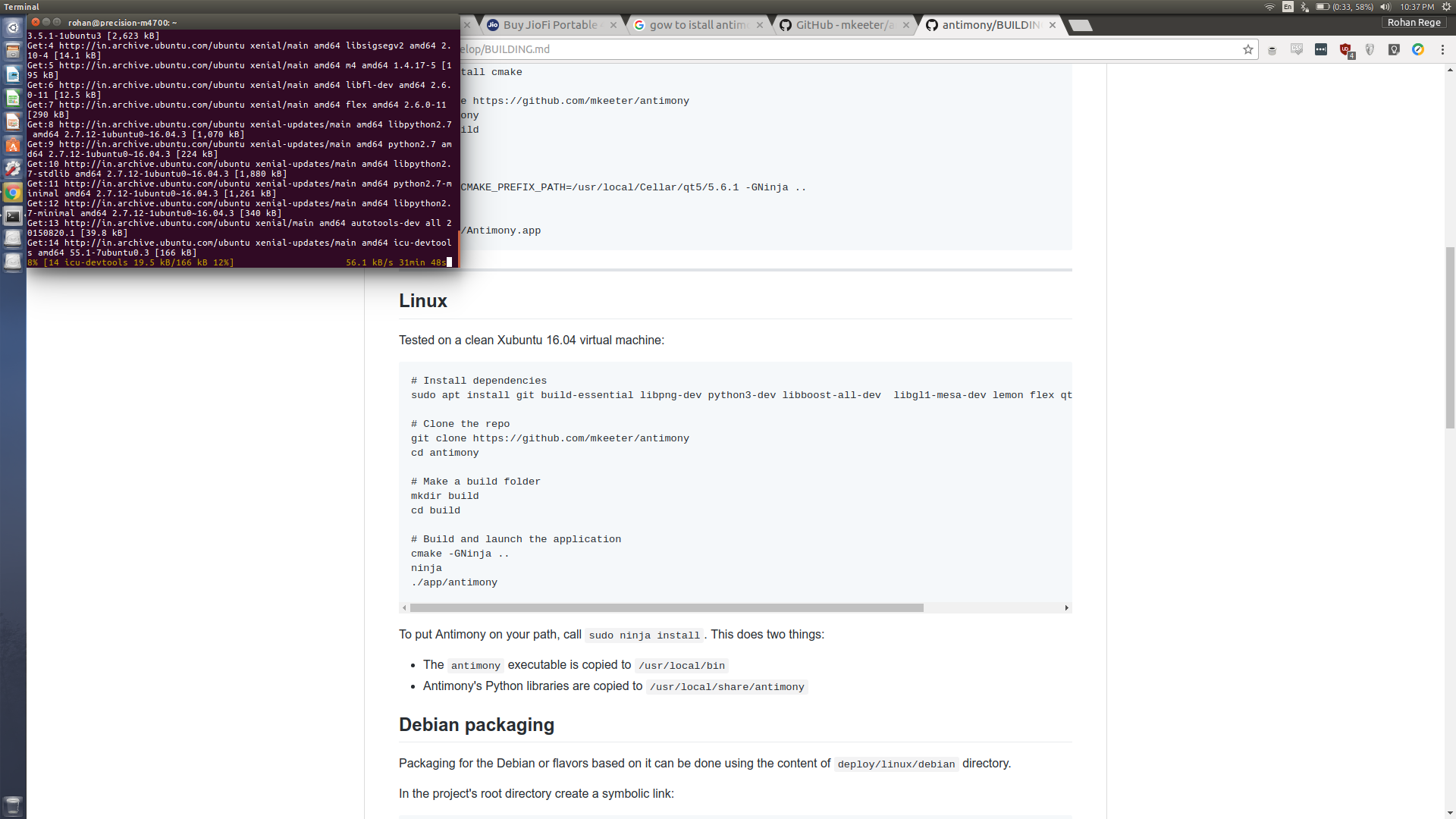
git clone https://github.com/mkeeter/antimony
cd antimony
mkdir build
cd build
cmake -GNinja ..
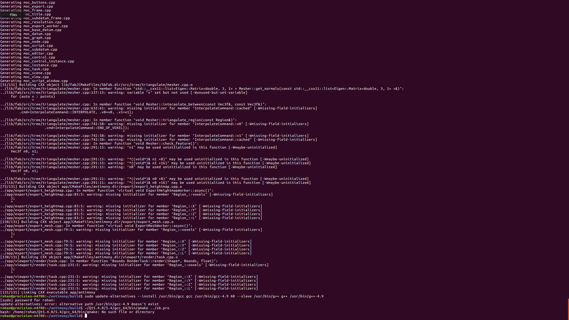
You may come across lots of verbose output, it looks scary but it works.
Also dont forget the periods.
ninja
./app/antimony
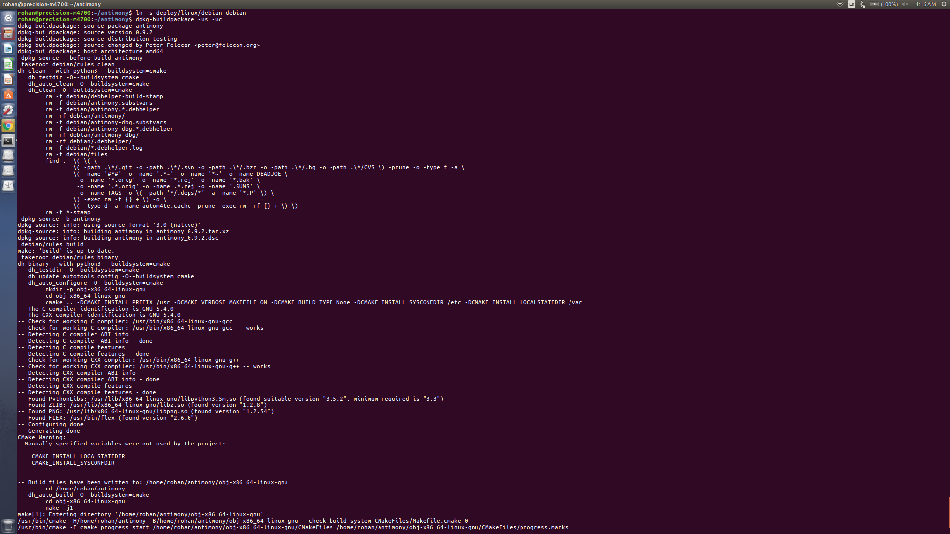
I have also compiled a debain of antimony is anyone wants to use it. They may download it too. To compile the debain package create a symlink and then build package by:
ln -s deploy/linux/debian debian
and then
dpkg-buildpackage -us -uc
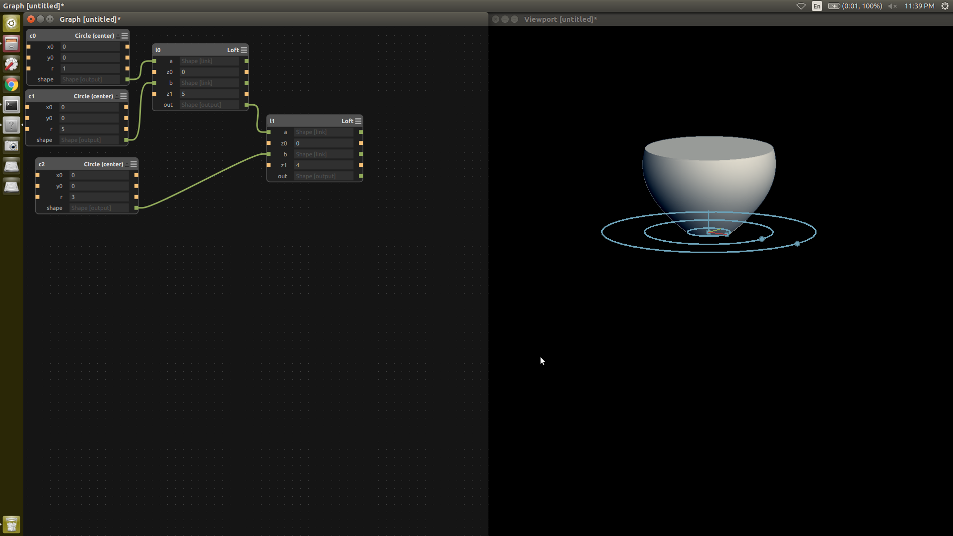
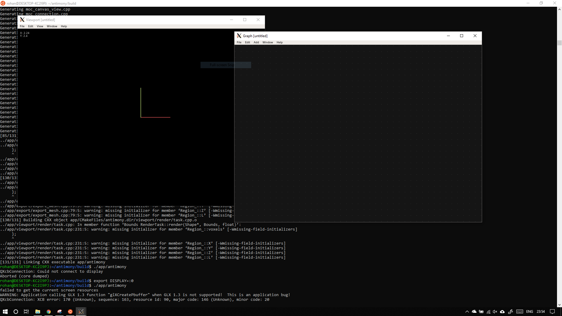
Antimony has two windows graph an viewport. Viewport shows the output model. In the graph tab we add windows to add geometric primitives.

To create a circle right click in the graph window and select 2D -> Circle -> Circle (centre)
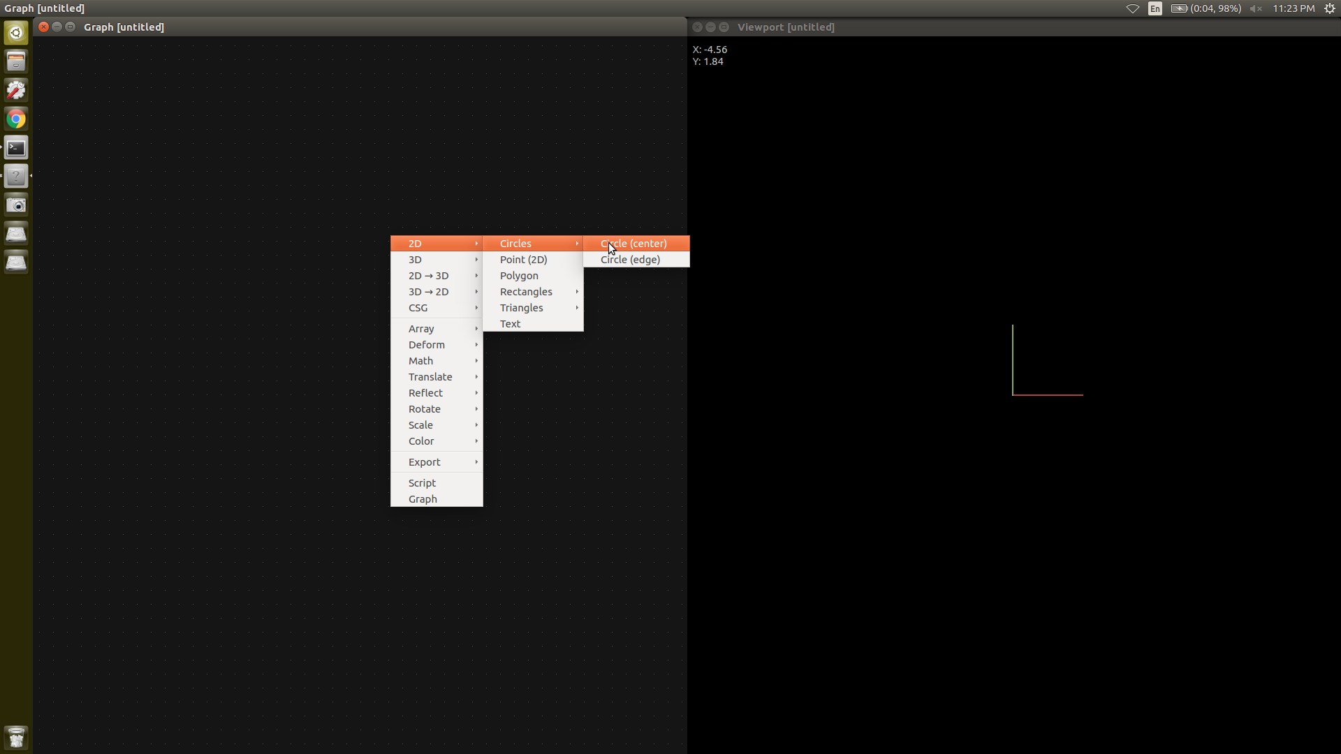
I plan to make a simple pot like shape, So I have added 3 cirles of required dimensions. To tranfrom from 2D to 3D use the loft command.
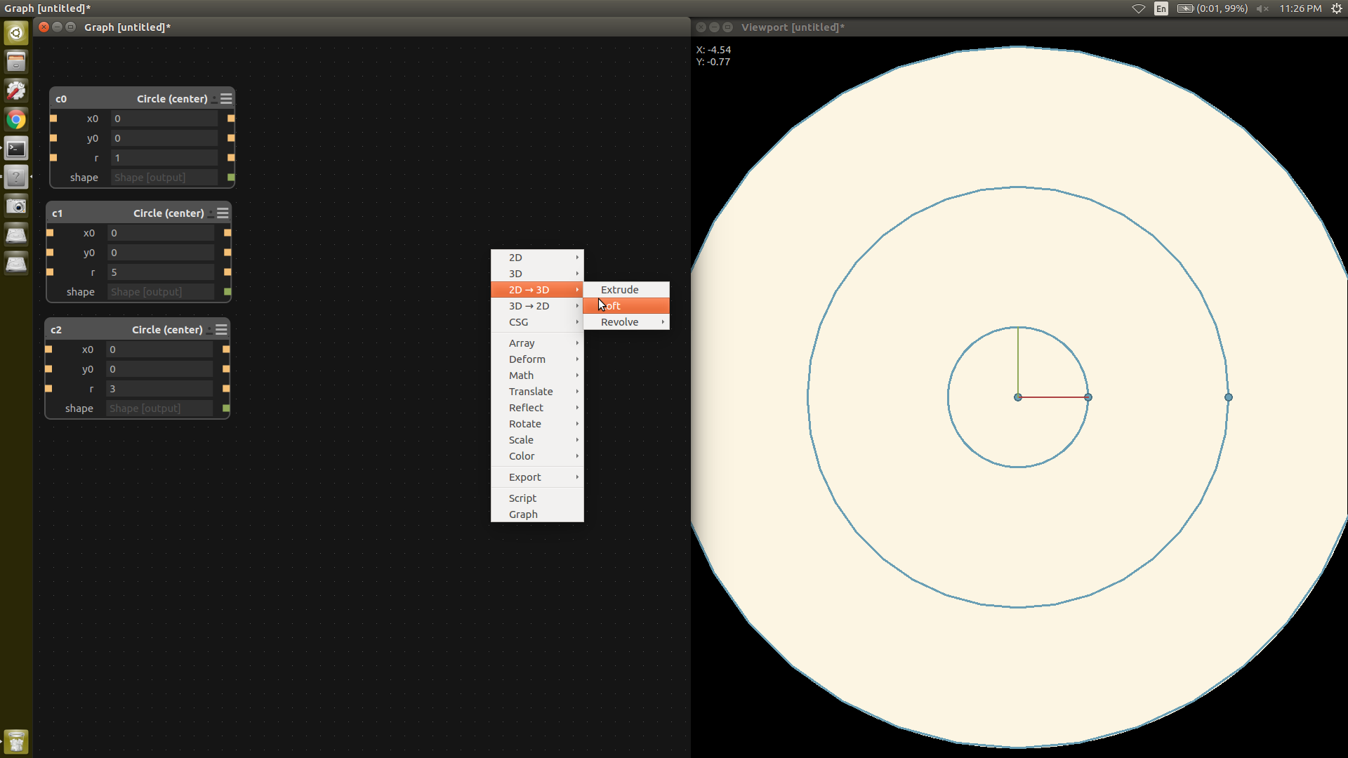
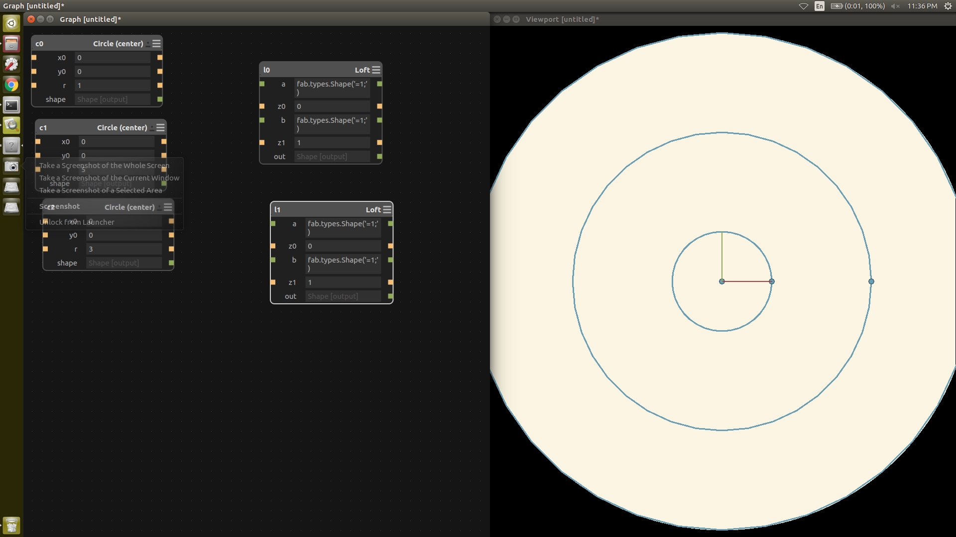
The green sqaures are the output, while the yellow squares are the inputs, by connecting the output of circle command to the input of
loft command we can create a loft.
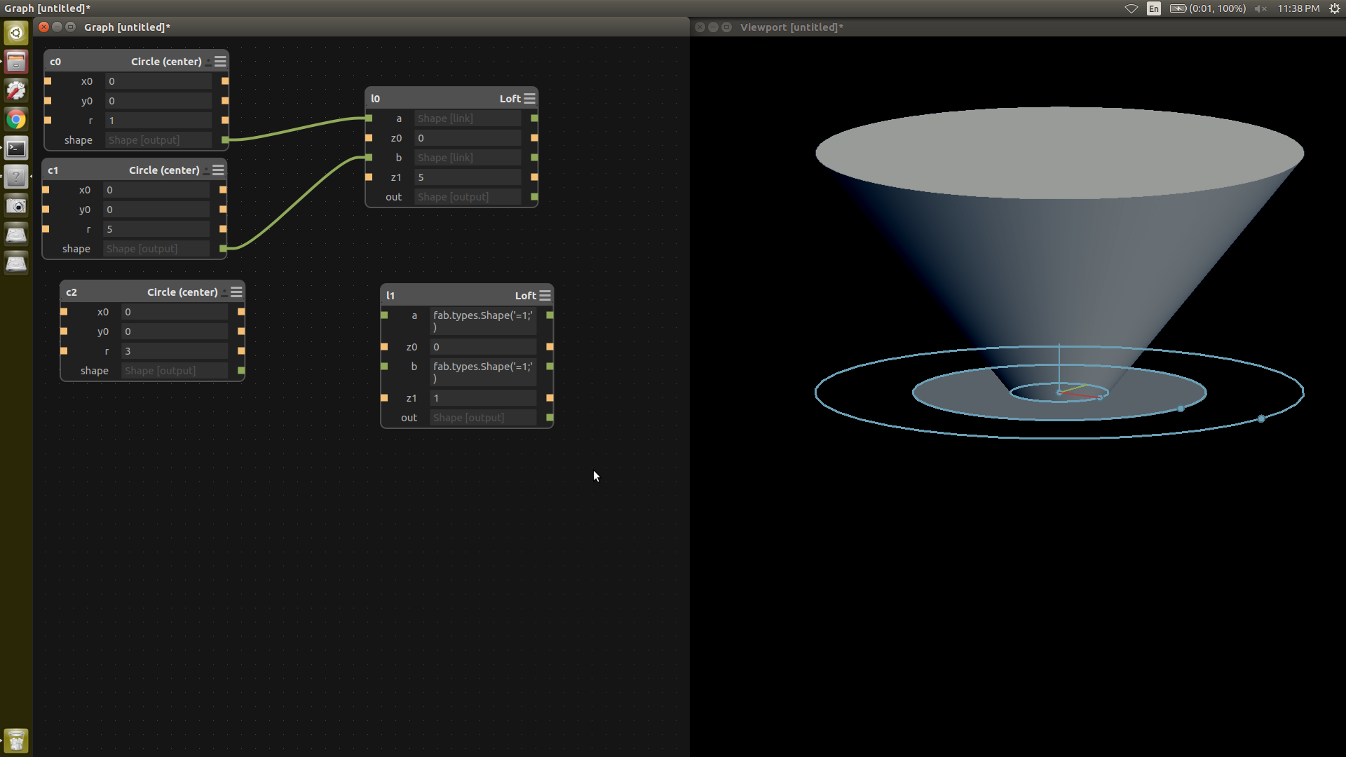
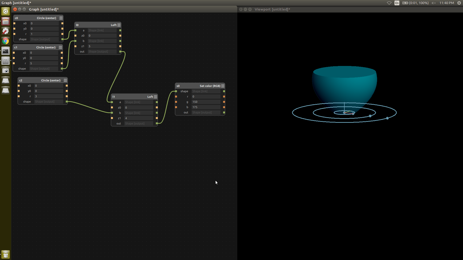
We can also add color to the file by using RGB values.
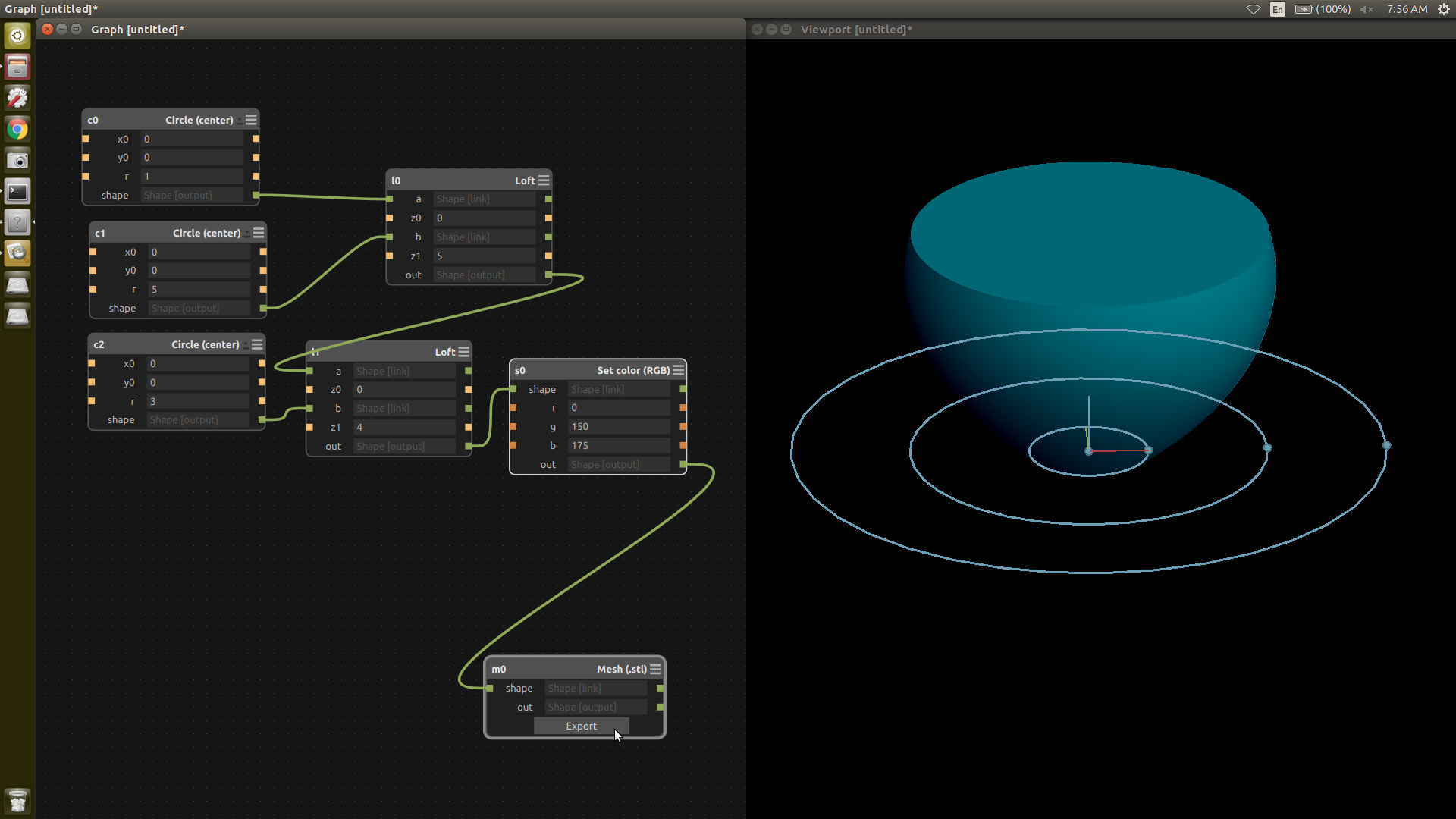
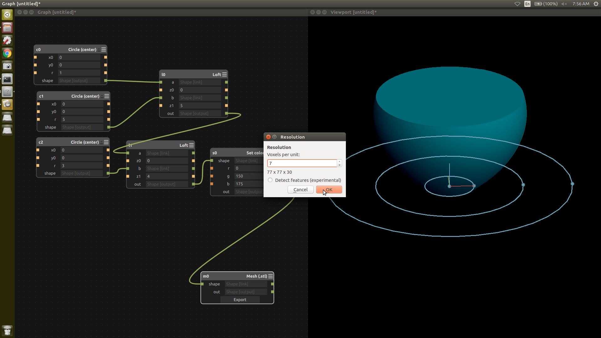
Now we export the file either as mesh (stl) or as png. To export as png right click -> export -> mesh
Antimony can also be installed on windows. Rather than bulding it on windows, I prefer to compiling it in the Linux Subsystem for Windows,
then using a display like Xming for windows. This acts an external display and can accesed by using the export display command.
This worked fine on my setup but your mileage may vary
All the antimony files can be downloaded here
Audio
1: Audacity
Audio is relatively new area for me. I have used ffmpeg before to convert videos downloaded from youtube so this time I am trying out audacity.
The main problem while recording somwething on mobile or without professional for that matter is that there is lots of noise, and lots of unwanted blank spaces.
We can edit this and clean the audio track with the help of audacity.
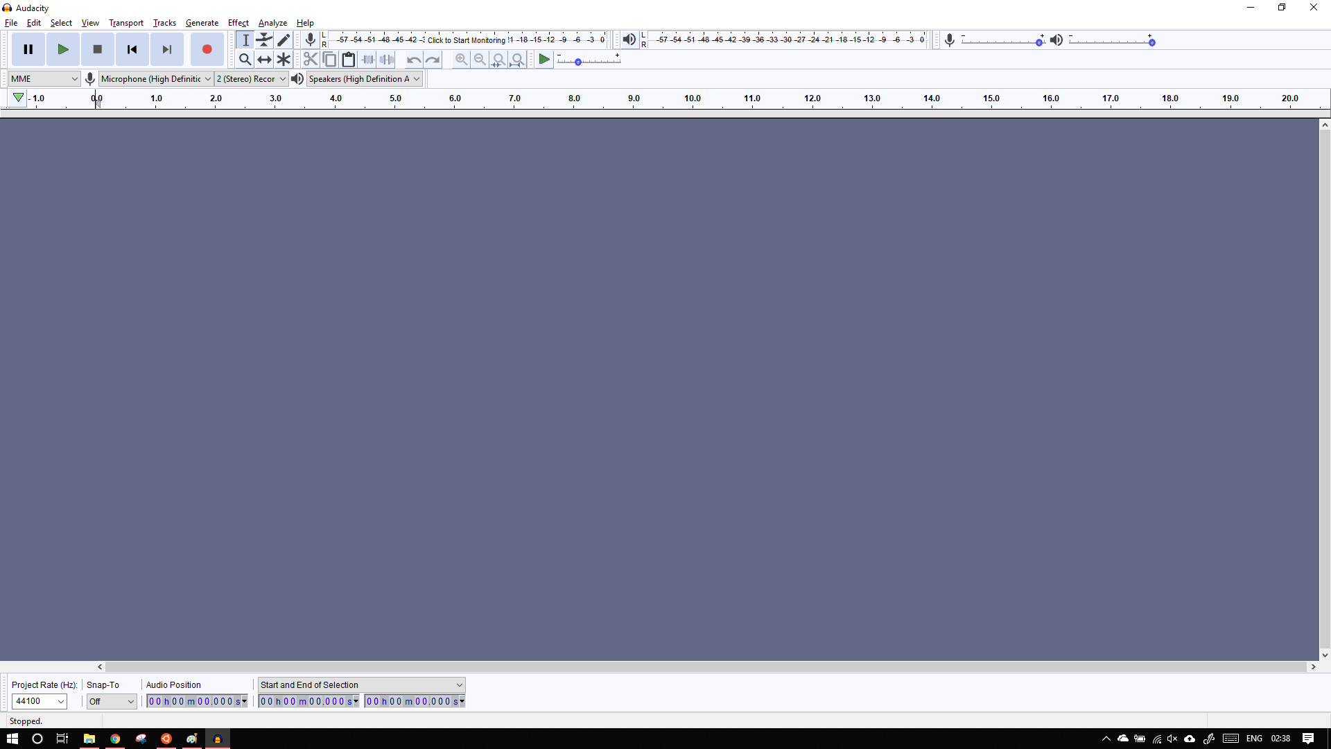
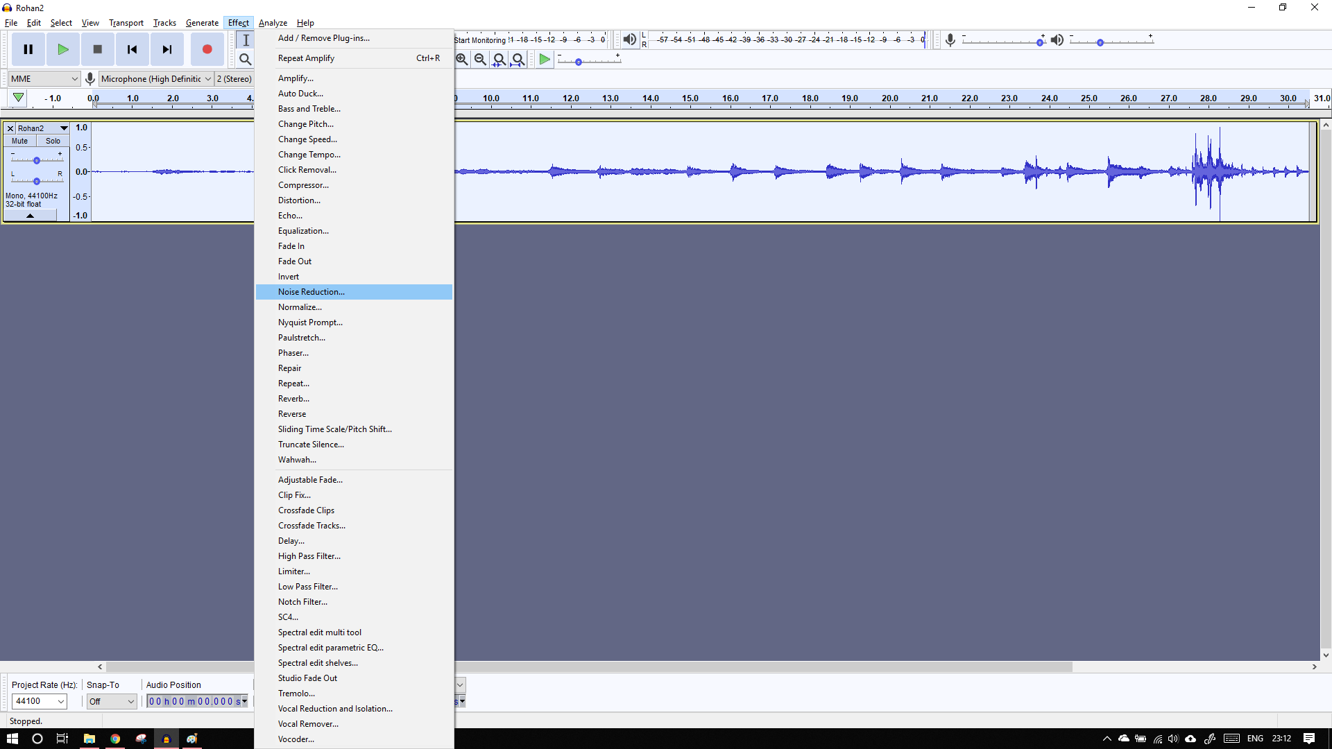
The UI of audacity looks like this, import the recorded file by going to file -> import -> audio
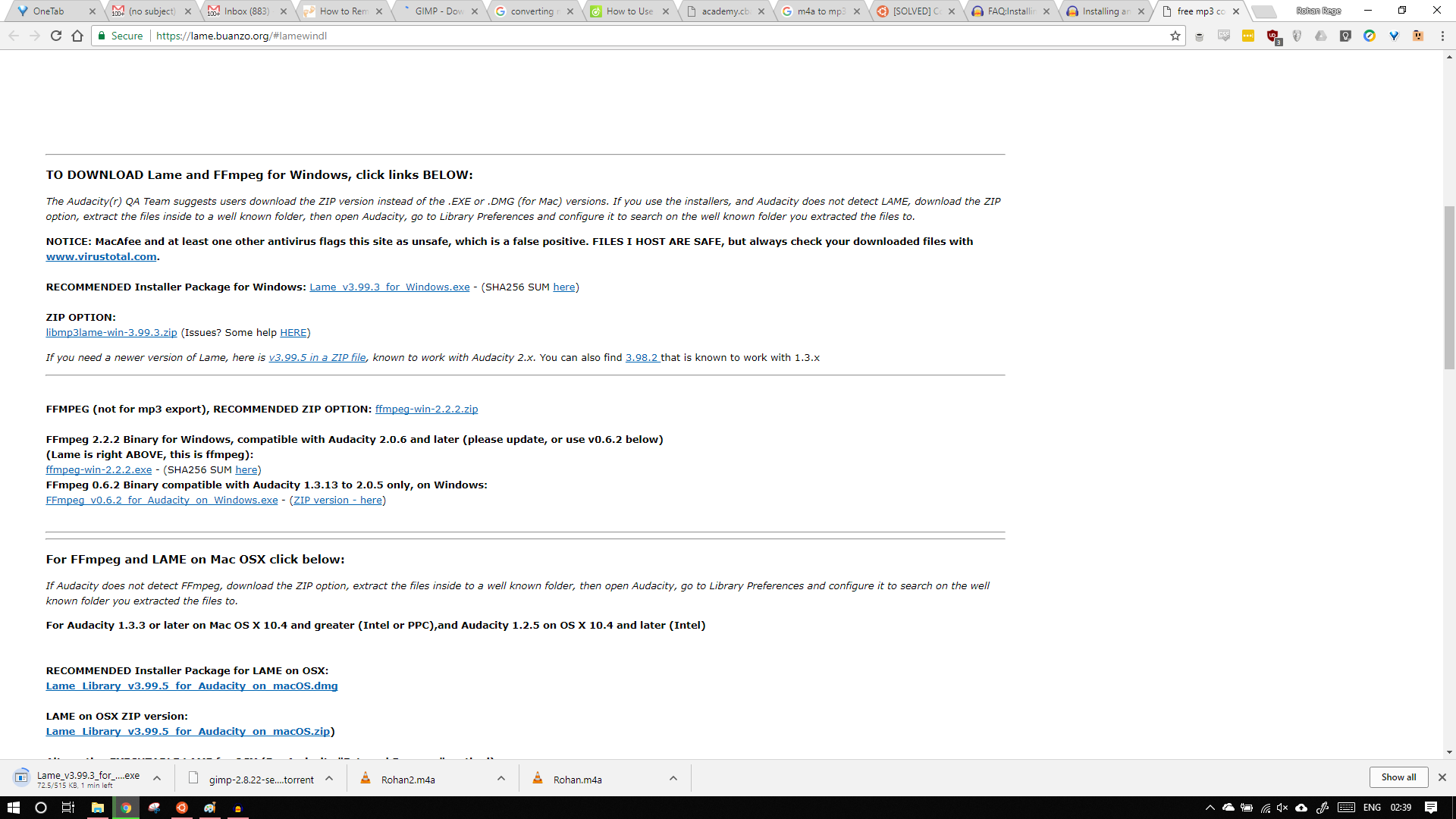
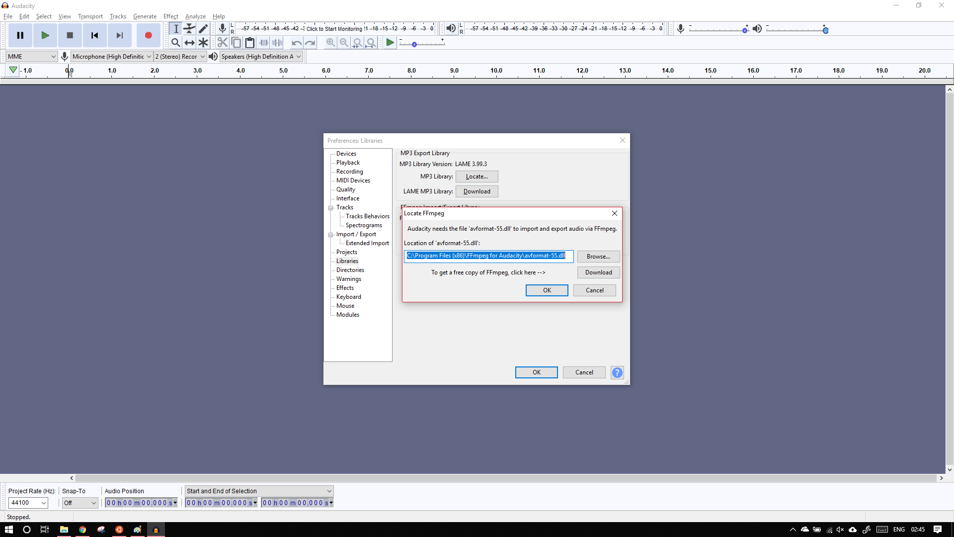
To export files in mp3 we need to have the appropriate library installed.
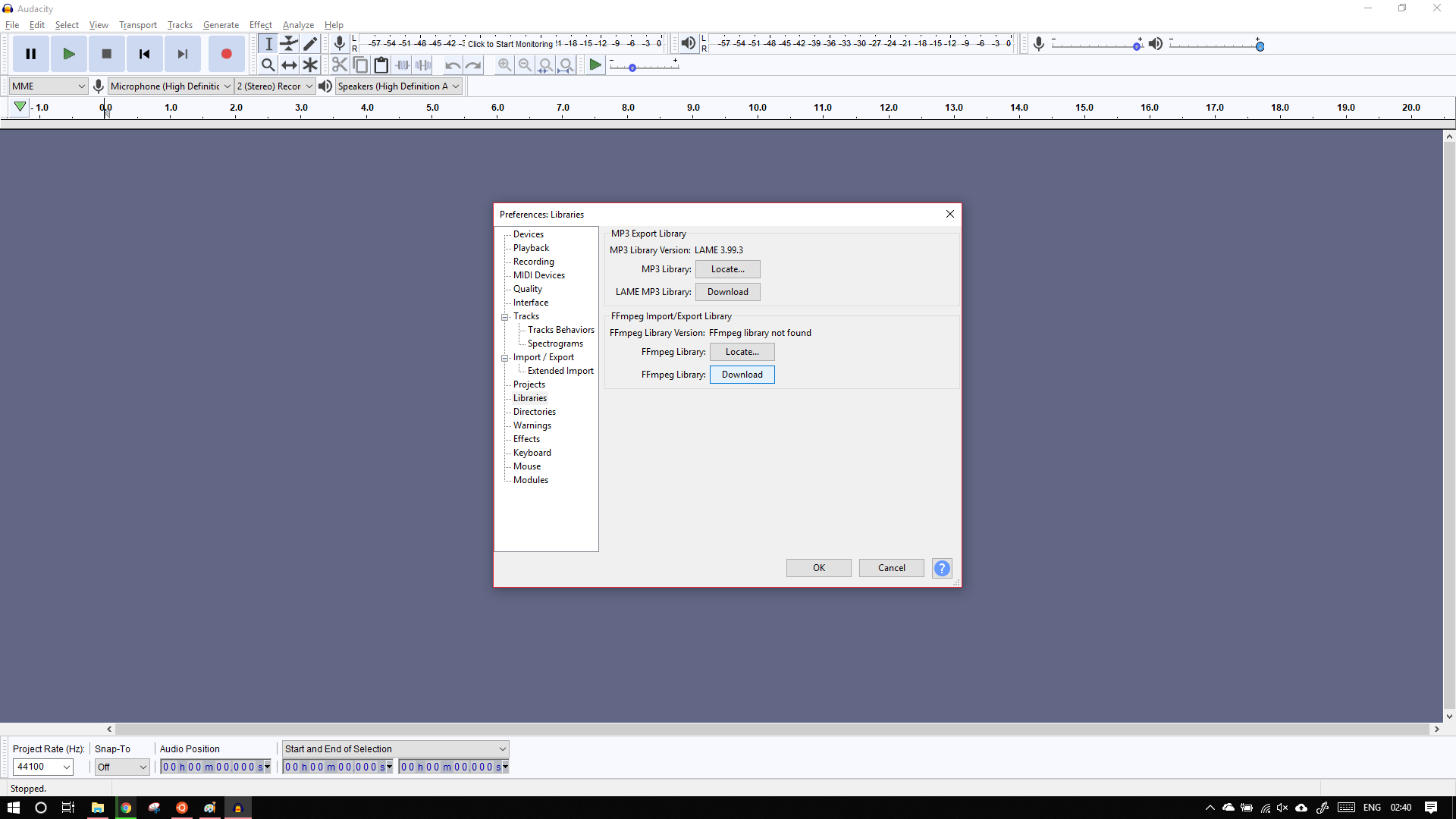
These are available in preferences -> Libraries
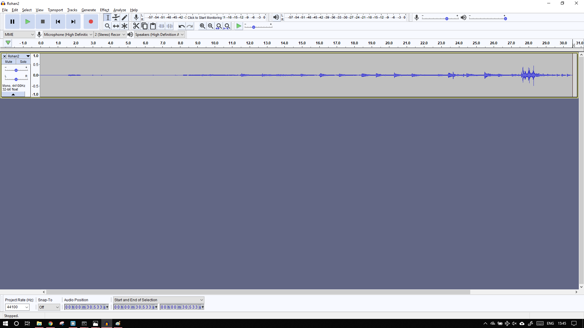
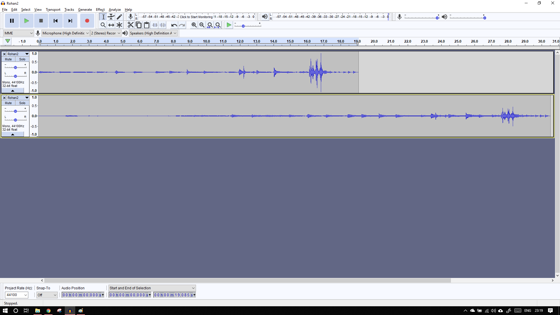
As we can see from the graph, The audio seems very low, if we play it there is lots of noise present. You can see that the actual audio starts at about 2sec mark. Everthing behind it is unwanted noise.
First, I amplified the track to my liking.
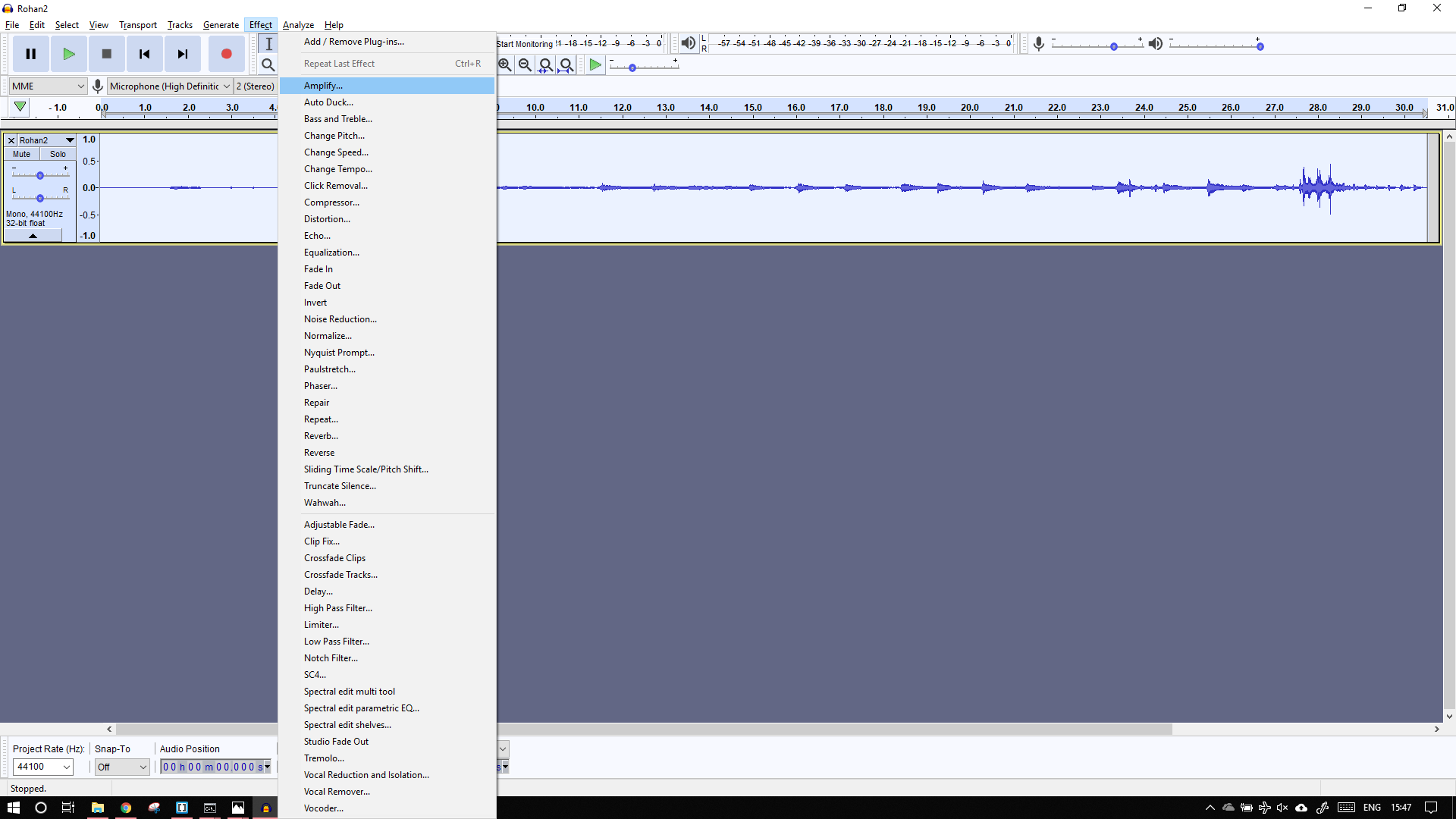
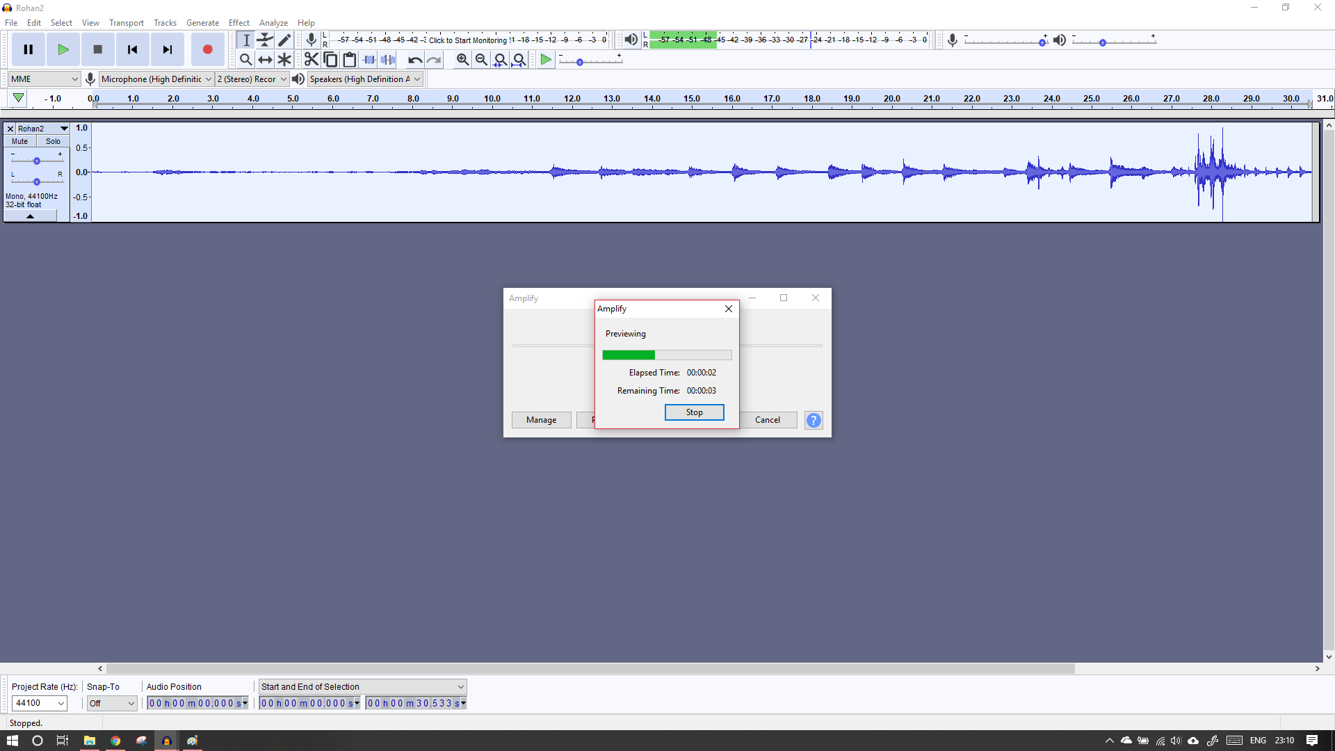
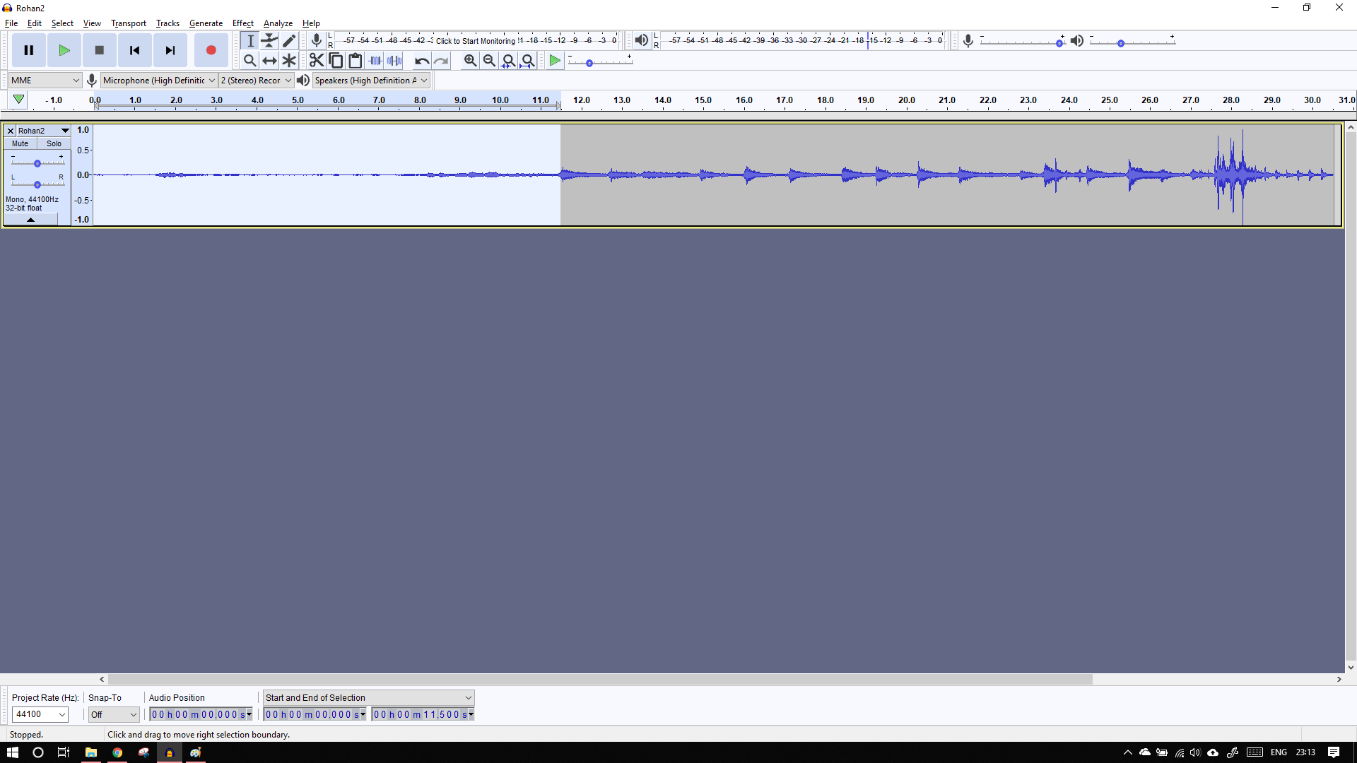
You can see the wave much better now, espically at the 28 sec mark.Now to remove noise again go to effect -> noise reduction
Select the noise area, for me it is upto the 11sec mark.
Now again go to Effects -> Noise Reduction, but this time select the whole, audio file as we want to remove the noise from the complete file.
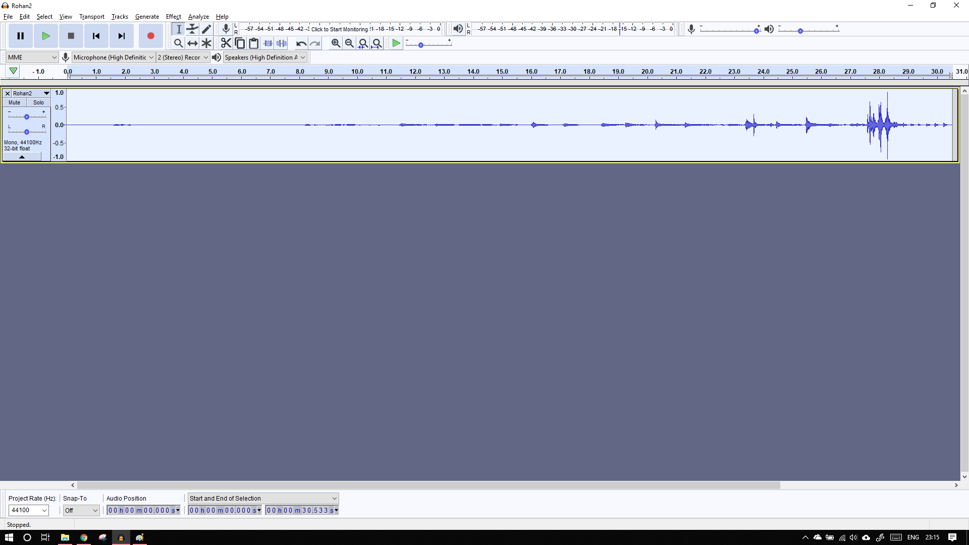
Now we cut the unneeded area from the track by usng the cut command.
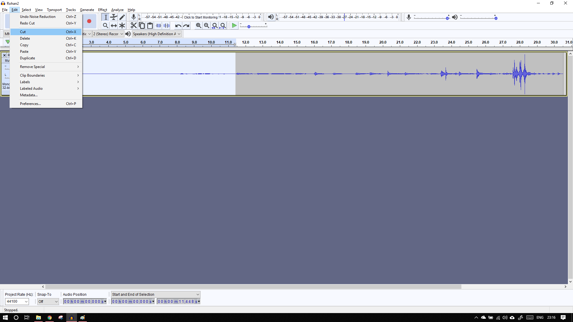
For comparison I have imported the orignal file again, you can easily see the difference in this picture
To export the file, go to file -> export -> Export as ..

After listening to the both the tracks I can see that the audio is not completely cleaned, if anyone knows how to do it please tell me.
The original recording (m4a) and the edited track (mp3) can be found here
For my final project, I'm planning to run an experiment. For this I'm growing small patches of azolla. I have created 16 unique combinations of beds.
I have tried to design them in solidworks here.

I'm planning to use a basic tray of 1ft X 1.5ft.
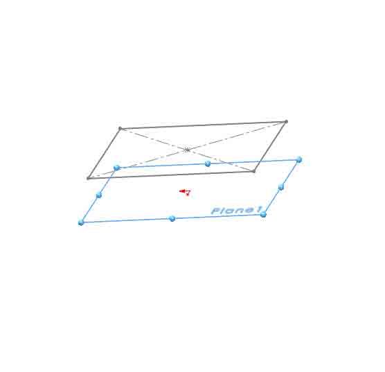
These are not exactly rectangular, they are lofted. Hence to make a lofted tray, I decided to use the multiple plane approach.
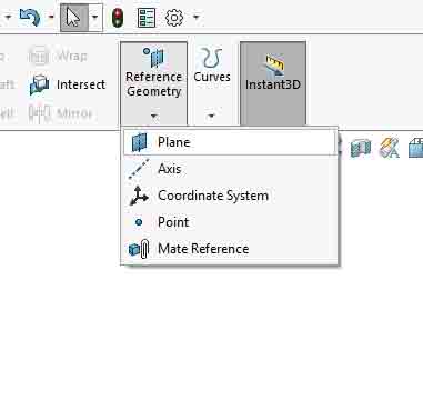
I created a new plane. Using the reference geometries menu.
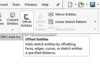
I then used the offset entities option, to create a small rectangle superimposing the original but in a different plane.
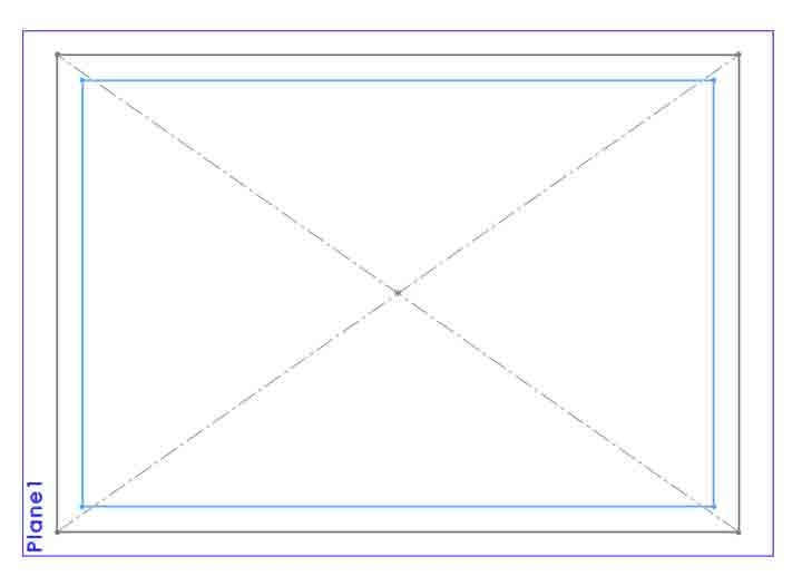
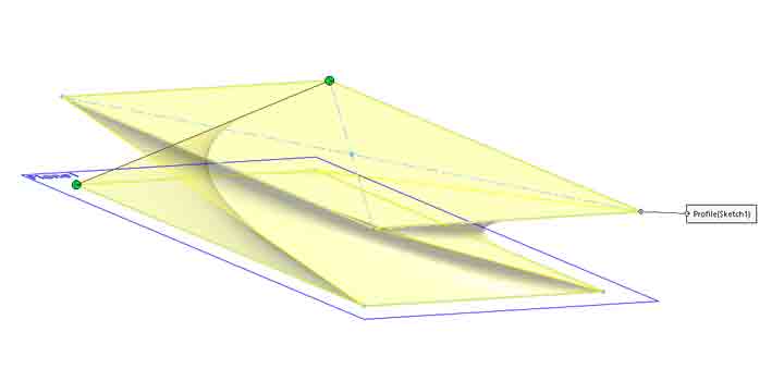
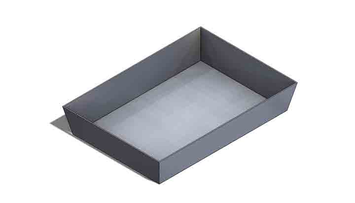
I lofted the 2 surfaces together by using the loft command.
Becareful while choosing the flow of solid lines as it can make or break the loft
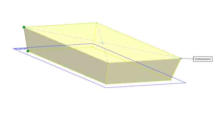
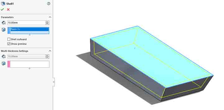
next I used the shell command to shell the body. To create the tray required.
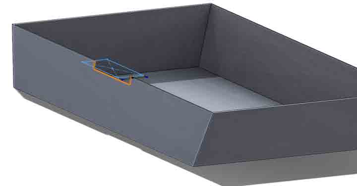
The next part is to create a housing for the electronics
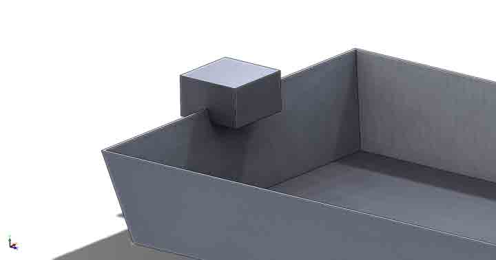
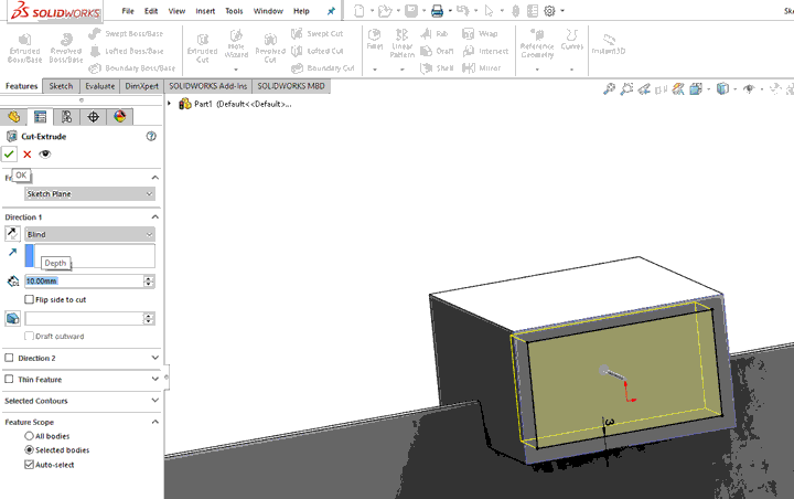
I used a the cut extrude command to cut through one of the walls of the tray.
I then designed a square box of around 50*50mm with cuts on both sides.
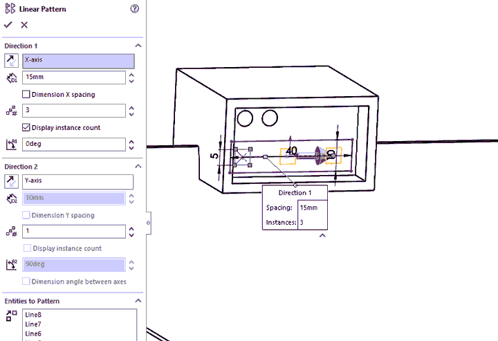
I again used the cut extrude command to make holes, LED placeholders (Using the Linear sketch pattern) and holes for wires.
I made same place in the back for electronic PCBs and circuits.
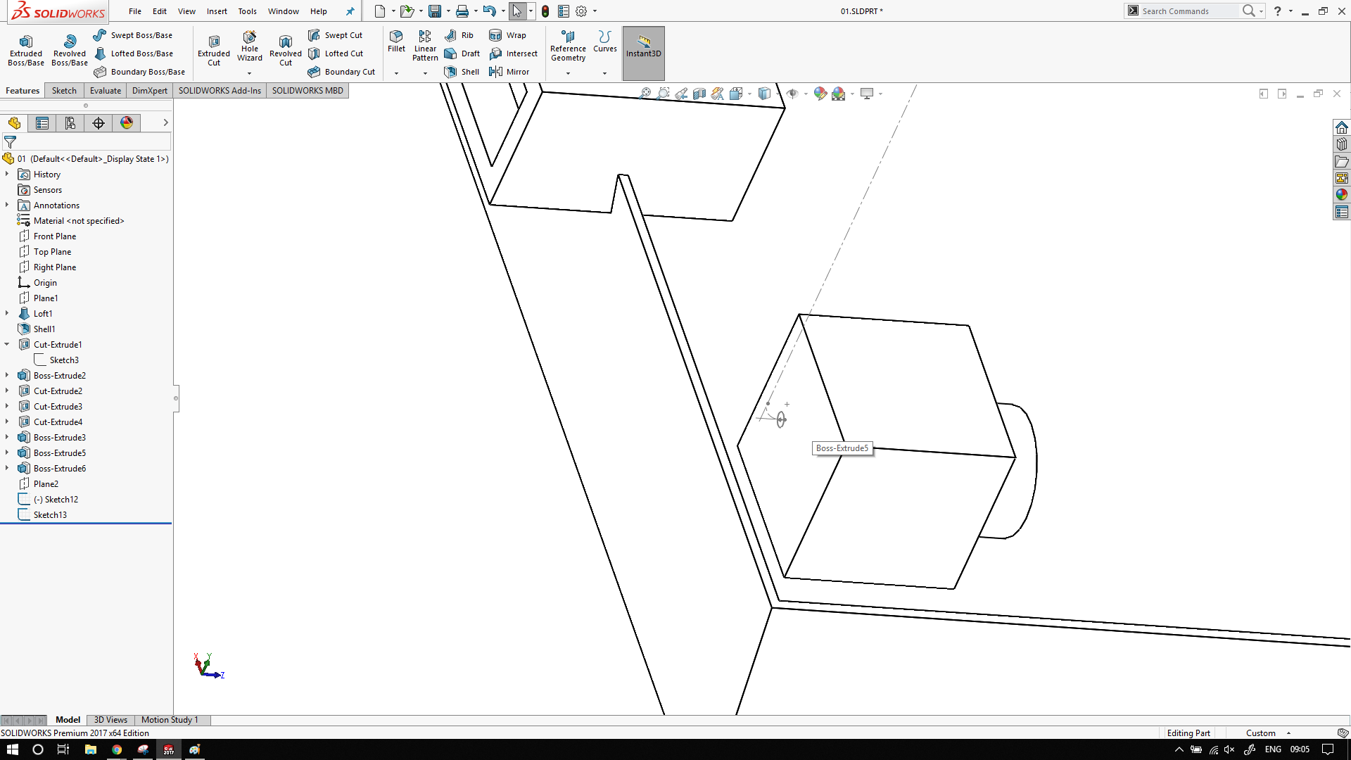
For pump I've made a simple Square box with cylindrical front.
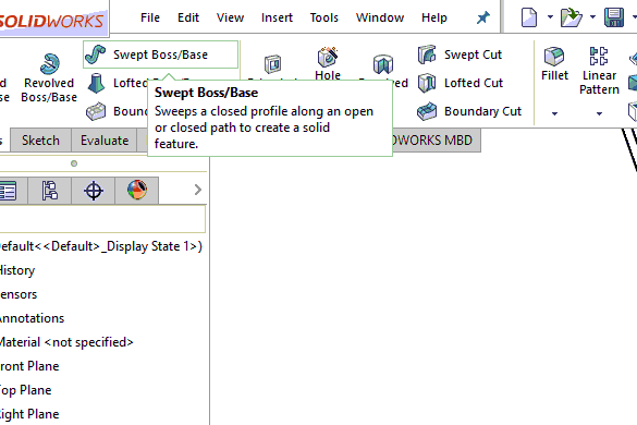
To show the pipe for the pump, drew a new sketch and used the Swept boss/base tool.
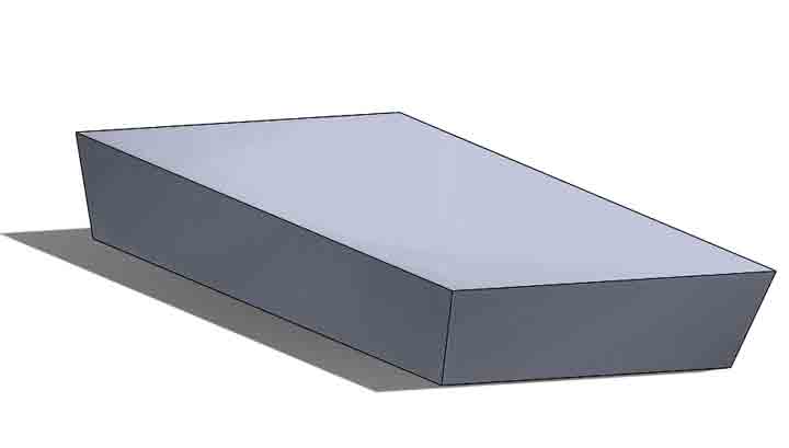
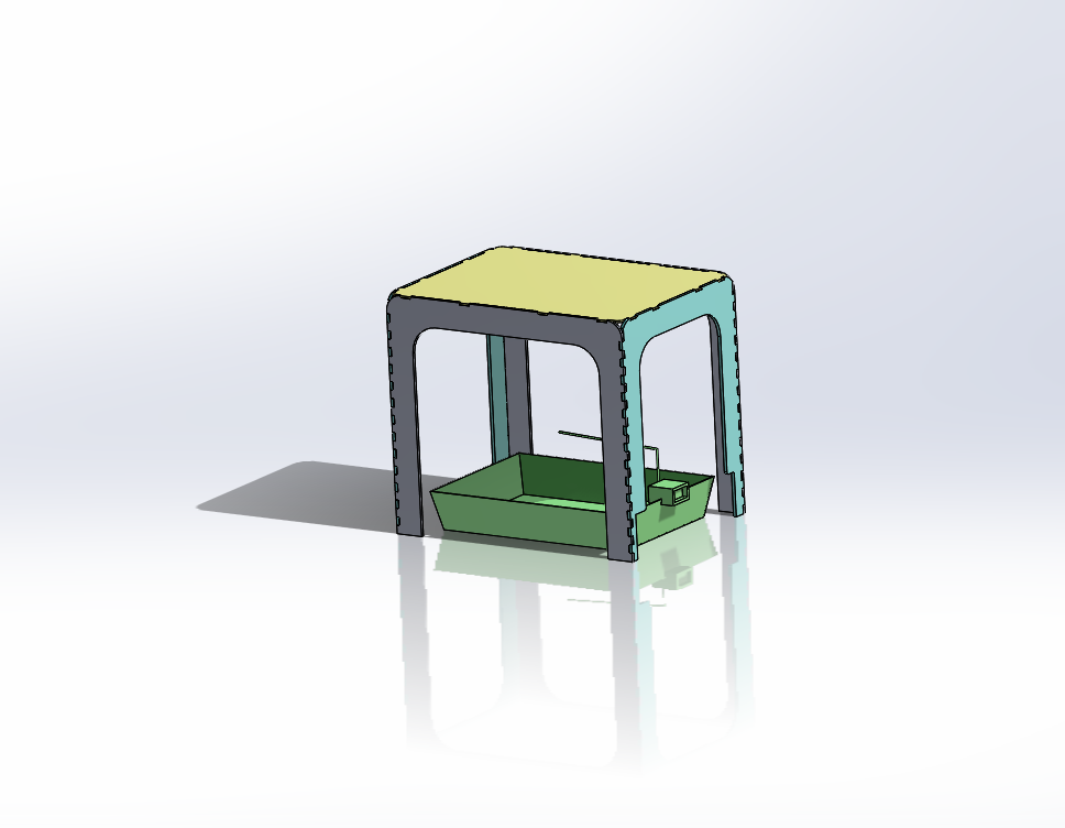
Final Output:
This is my current Model for final project.
The complete cad model is available here
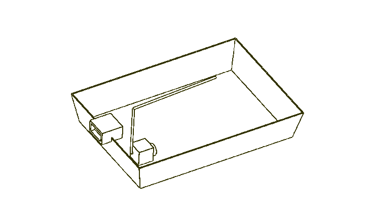
For my final project, I've to design something to keep my circuit.
There is a high chance that it might come in contact with water.
I decided to make enclosure for it. I was going to make it in SW, but my global evaluator suggested that I try a different software. I decided to go with antimony
Antimony evolved from a parallel universe where there are no drafting tables. Antimony is like a CAD package for programmers. I'm liking the way he thinks
Initially I created two rectangles the smaller one has the dimensions of the my milled circuit board.
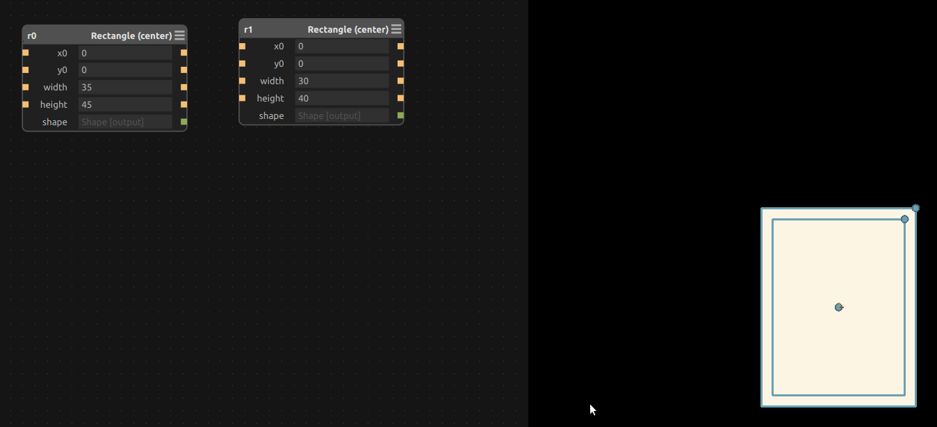
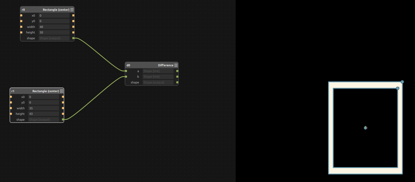
Then I used the difference command to get the rectangular border.
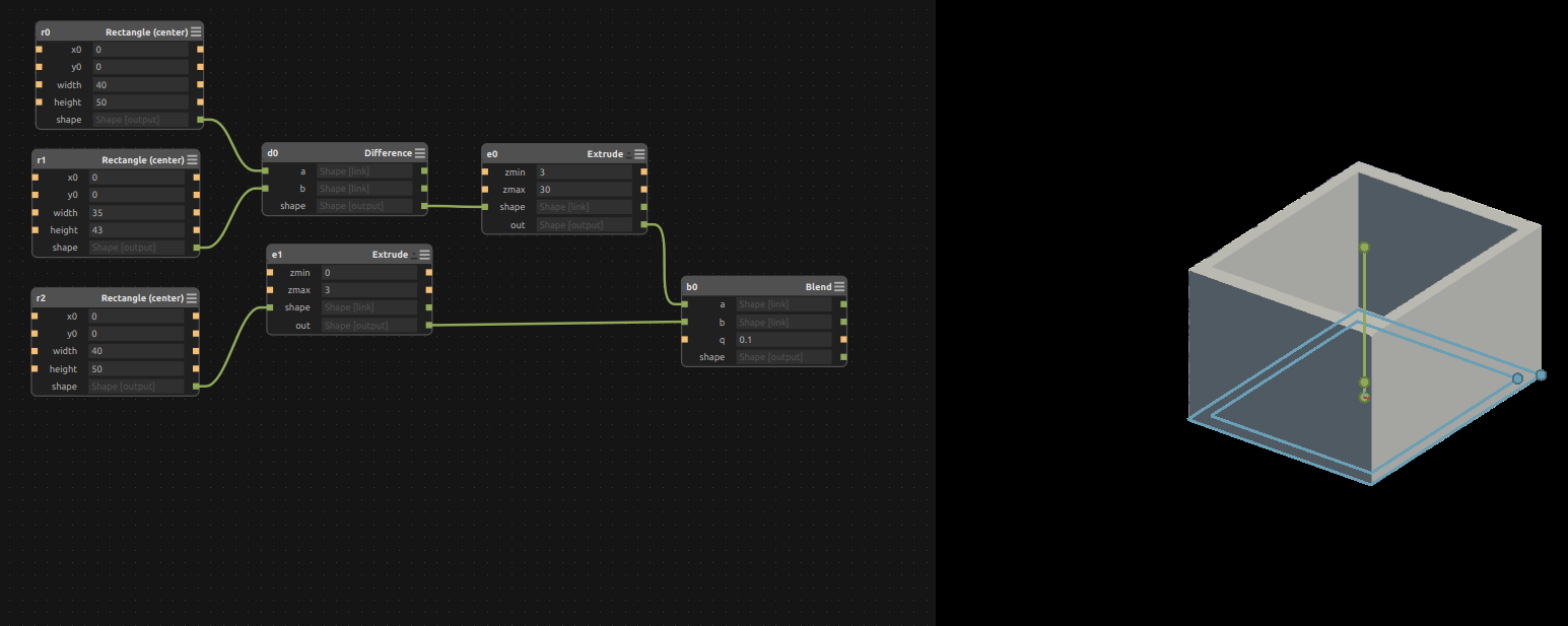
I extruded the border rectangle with help of the extrude command to a height of 27mm
If you see clearly in the image below I have started from the z0 = 3 and zmax = 30
This extrudes from z = 3mm to z = 30mm, efffective height of 27mm
I did this because, I needed some kind of base.
For my base, I made a rectangle of similar shape of the larger rectangle
Now that I look back, I could have reused the prior program rather than creating a new rectangle..
Next step is to extrude to fill the bottom of the model.
I then blended the two extrusions together using the blend command
Next part was to export the model, this time a I also exported the depth map of the model along with the stl file
The depth map looks like this

I also generated an STL file which was then sliced and sent a 3d printer for printing.
It is available to download here
My final project render:
All the files are available to download here