Rohan Rege
Fab Lab Zero
Vigyan Ashram
<- Home
This week we had group assignment, this may cause the same image to appear on pages of multiple students
We are using the old version of FAB modules. Although the newer mods are better, it takes more steps to accomplish the same task when compared with the older modules.
This week were tasked with:
1: Group assignment:
Characterize the lasercutter, making test parts(s) that vary in cutting dimensions.
2: Individual assignment:
- Cut something on vinyl cutter
- Design, lasercut and document a parametric press-fit construction kit, accounting for laser kerf, which can be assembled in multiple ways
Vinyl Cutter:
We have the Roland camm Vinyl Cutter. I was, still am somewhat skeptic about the use of the vinyl cutter in a fablab. Nevertheless we set on the task of
profiling the machine. Instead of using the drivers, we used the fab modules to interface with the cutter. Fab modules can used/downloaded for free from the mods.fab website.
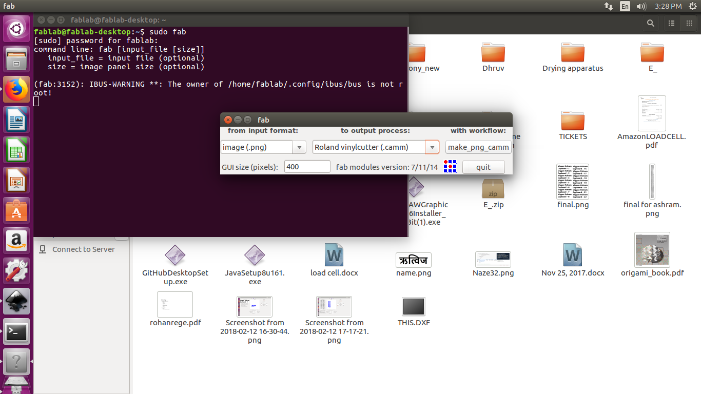
To run the module, use the $ sudo fab command.
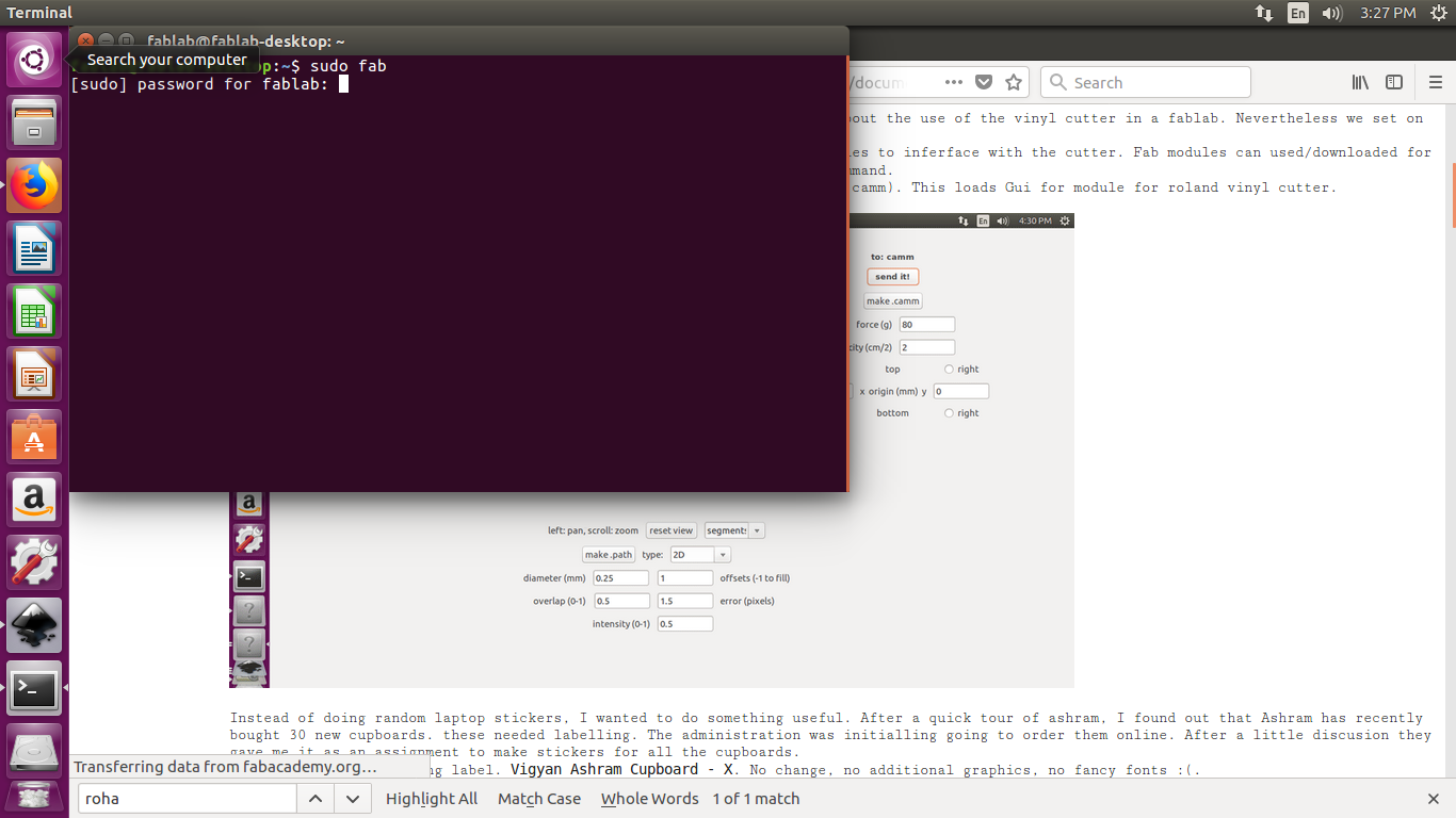
From the input select png and at output select the roland vinyl cutter (.camm). This loads Gui for module for roland vinyl cutter.
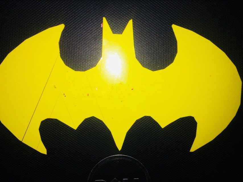
I had to do a design on Vinyl cutter, The yellow colour of vinyl reminded me of the old batman logo.
I downloaded the image from internet in .png format. it had some text written over it.

The image is taken from the 467printing website, and link to it available here.
Using inkscape, I removed painted black over it.
and then loaded it in fab module.
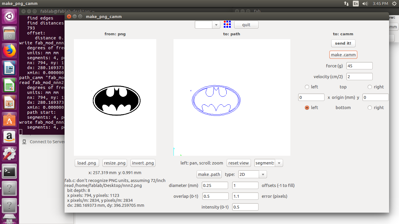
The output actually created two stickers, One of them I used on the computer itself.
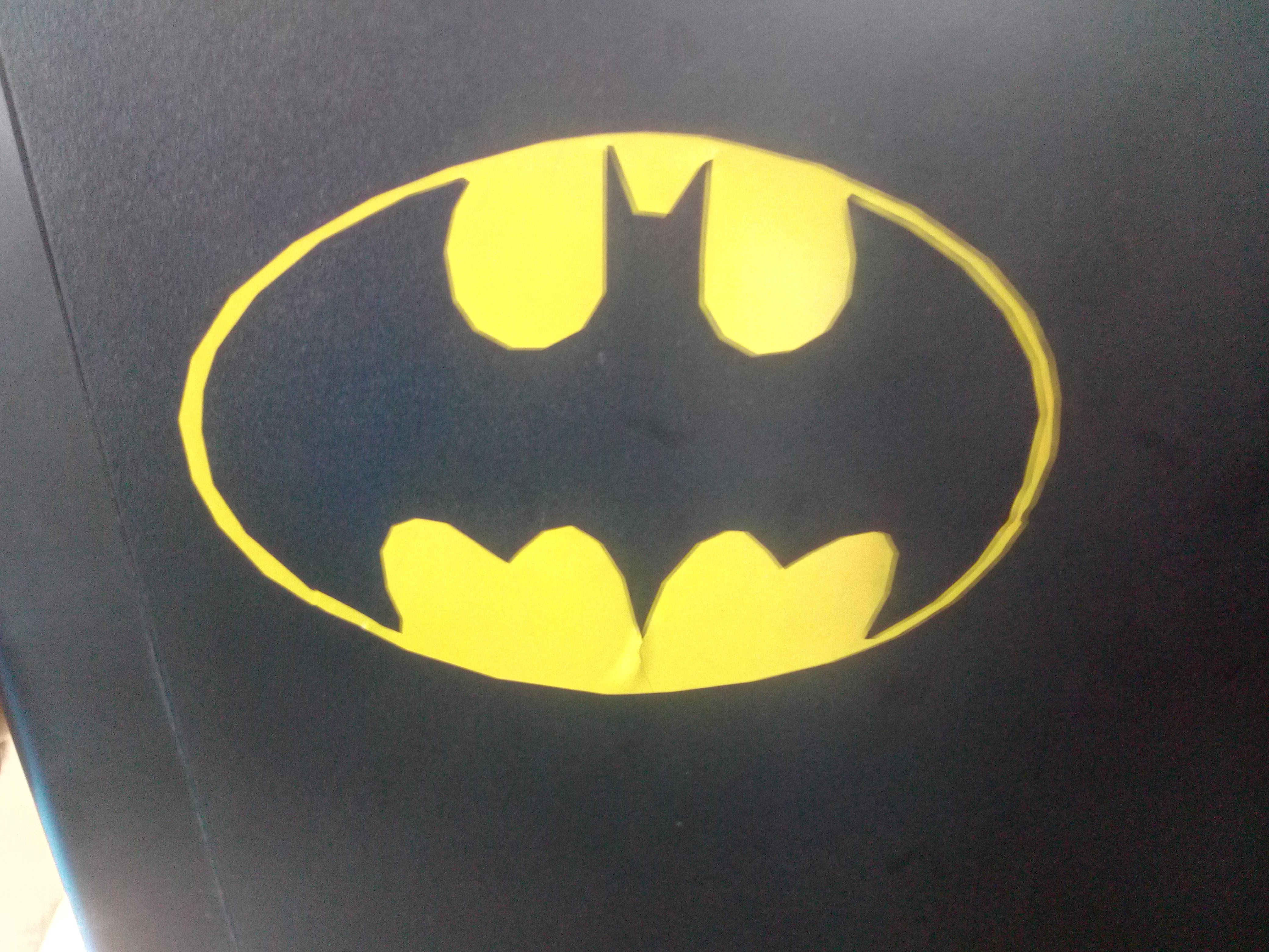
As you can see there is some blurriness on the right side of the pic. This is called ghosting. It is caused due to improper image processing by the camera and having shakey hands.
I had stuck the inside piece of this logo, i.e. the black part on to Kamlesh's.
He then later stuck his name on top of this sticker with red vinyl. (Also he stuck is inverted :D)
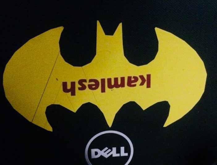
As you can see, there is no problem with the cut, its just ghosting.
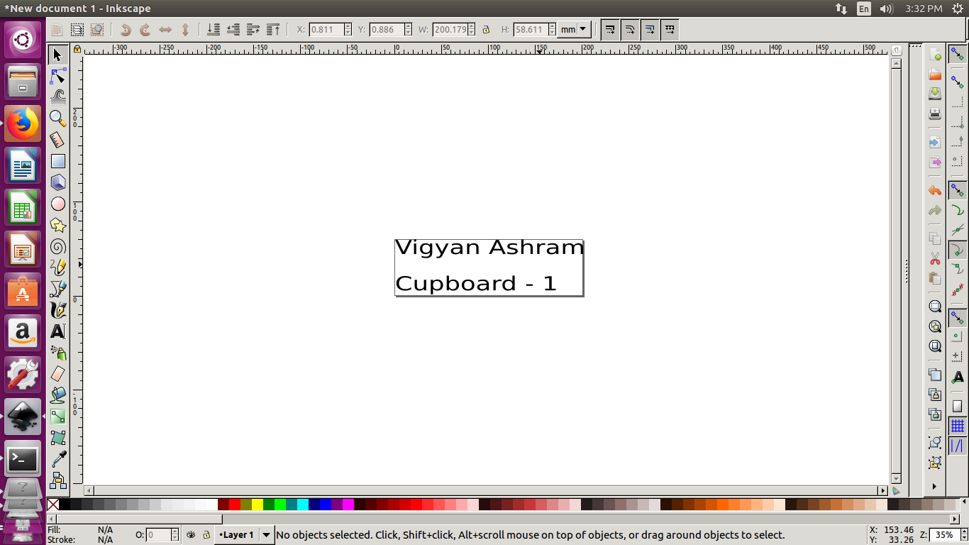
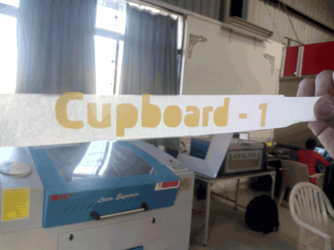
Instead of doing random laptop stickers, I wanted to do something useful. After a quick tour of ashram, I found out that Ashram has recently bought 30 new cupboards. these needed labelling. The administration was initially going to order them online. After a little discussion they gave me it as an assignment to make stickers for all the cupboards.
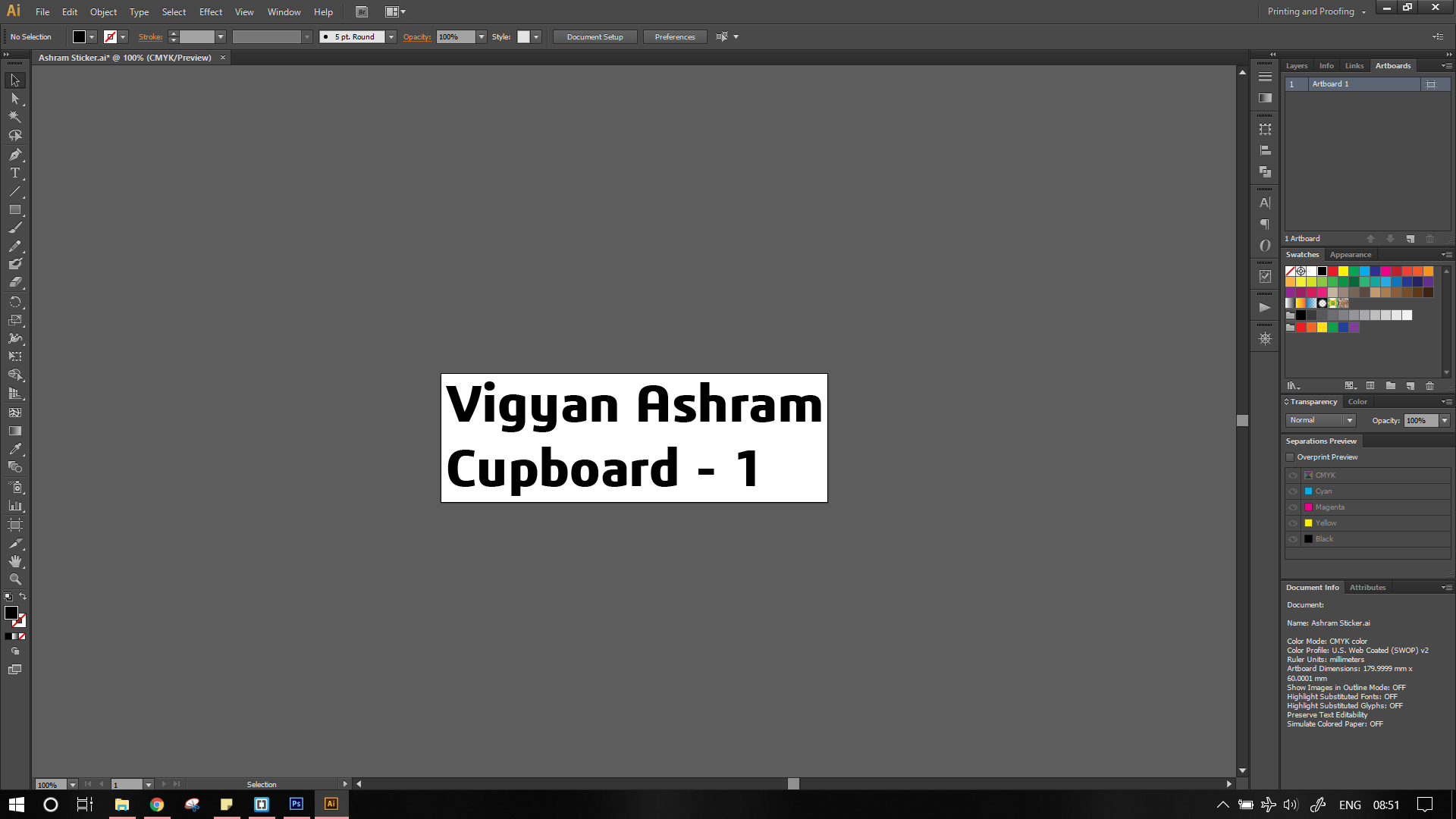
They wanted the following label. Vigyan Ashram Cupboard - X. No change, no additional graphics, no fancy fonts :(.
I first used inkscape for the to convert the typeface to png images. I edited the canvas to the required size of 60mm by 100mm and then select the text tool to add text
After importing in the fab module, the lines were not as expected, the whole image was distorted. Which is unacceptable.
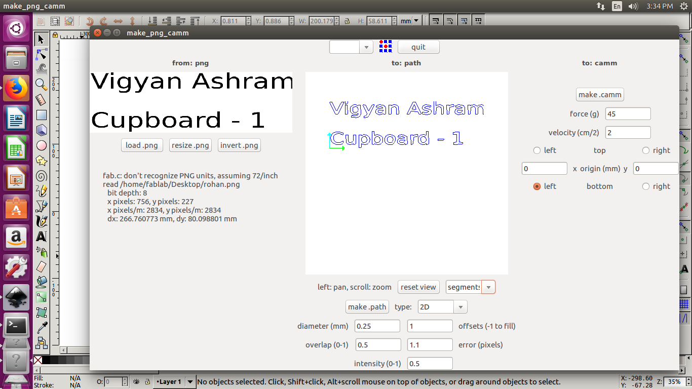
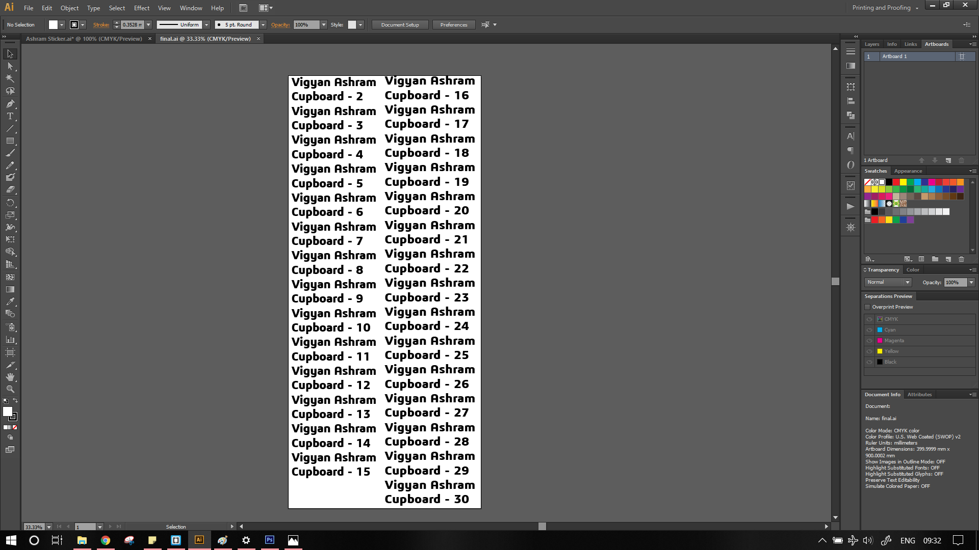
I decided to use Illustrator instead. I repeated the same process of adjusting the artboard to required size (60mm x 180mm) and adding text. I set the text height as 25mm (as decided with administration).
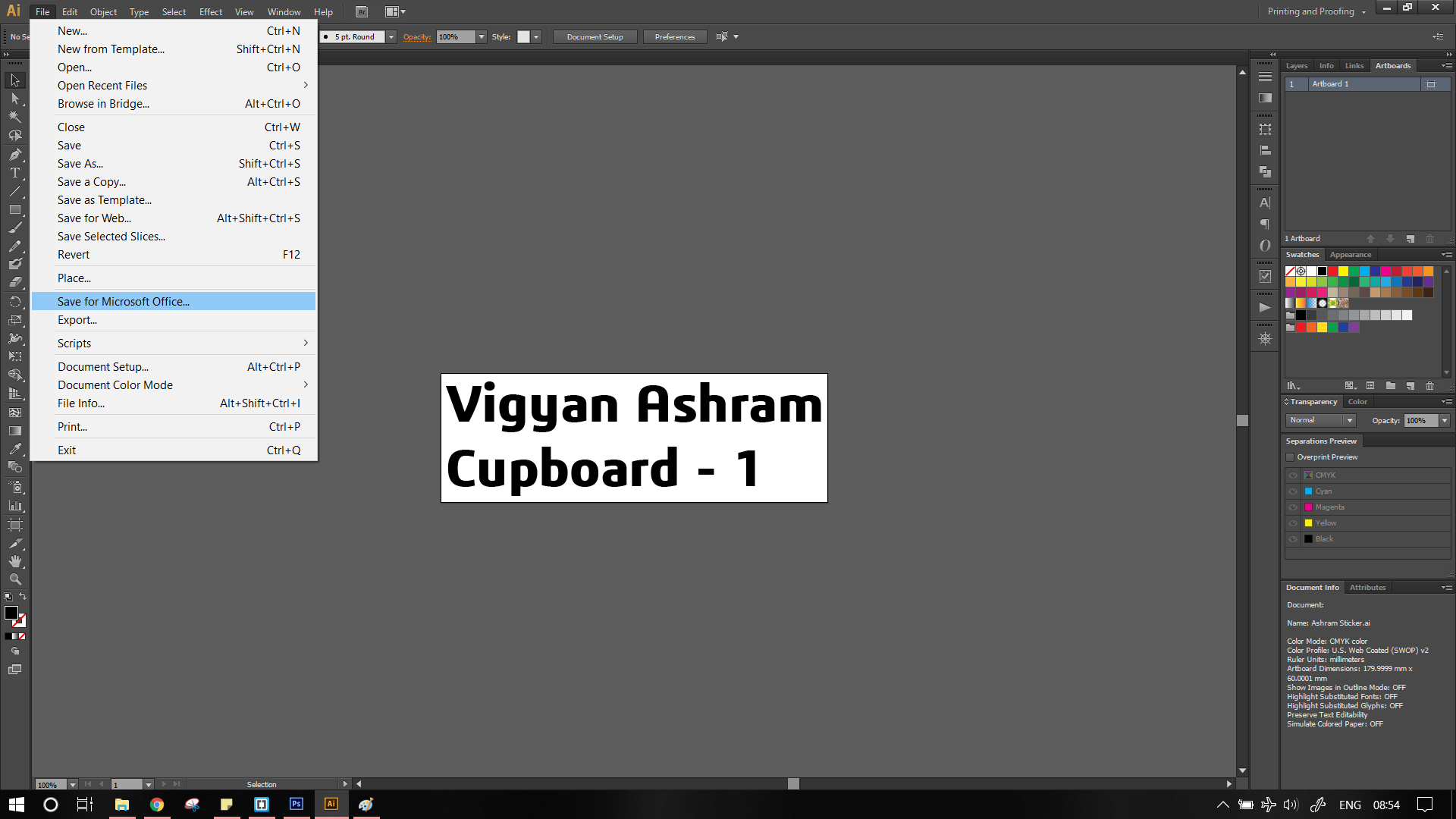
Next step is quite easy, export the image to png format, to do this use.
File -> Export for Microsoft Office
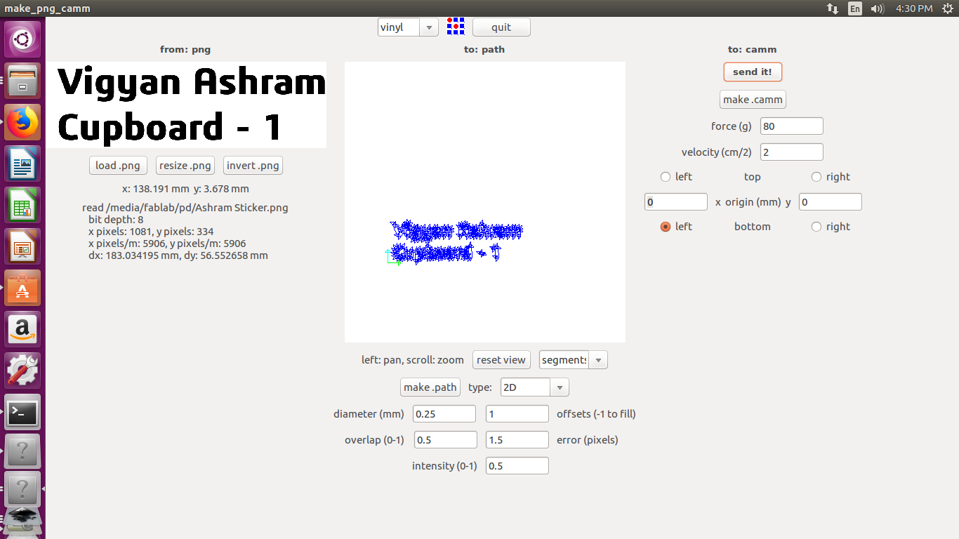
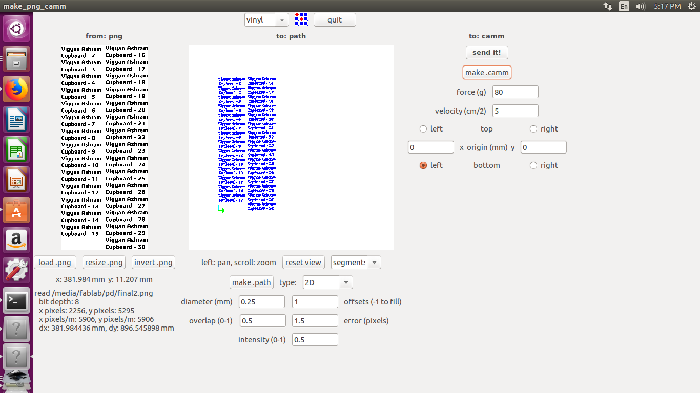
Then open the fab module. load .png -> make .path If everything looks perfect, set the origin either on machine or in the module. The next step is to set the force, I found that any force between 80 to 101 g is enough to remove vinyl. Your settings are dependent on the type of paper you are cutting. After double checking evething, select make .camm -> sent it! This will feeds the path data to the machine.
Do not disconnect the machine from laptop mid cutting. The module feeds data bit by bit. Disconnection causes the blade to return the initial postion
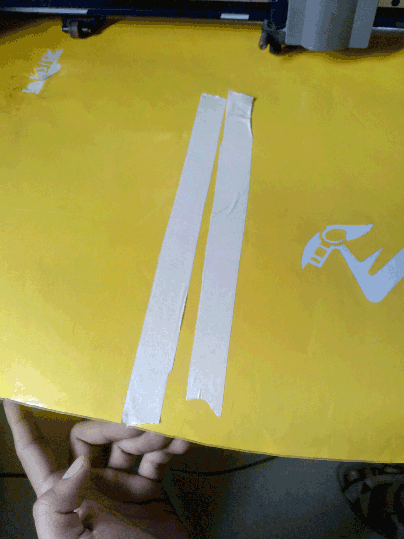
Individually removing stickers although fast, it causes the letters to be misaligned. I used a masking tape to remove the letters.
The next thing was to stick it to a cupboard in admin office for approval

Now, I created another file illustrator, with remaining stickers
And loaded it in fab module.
Now we wait for the job to complete.

The orignal files can be found here
Laser Cutter:
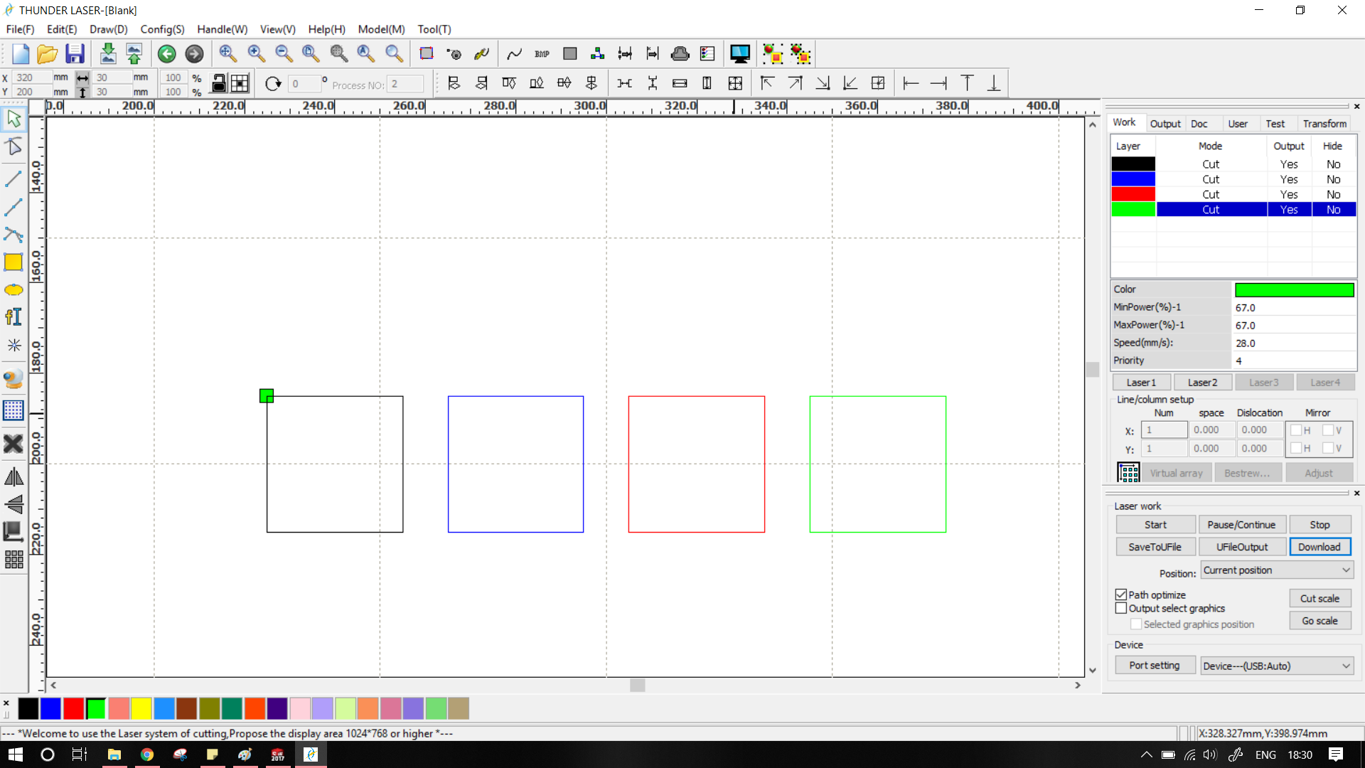
Vigyan ashram has two lasercutters one of them is epilog mini and other is by Sil (Suresh Indu Lasers). The group assignment was to characterize the laser machines. We decided to split in two groups of 4 people each. My is working on the Sil. I had previously used this laser, but never needed to calculate the tolerances. To calculate the tolerances I referred to google and previous years students. Most of them have Made a sample parts like squares or/and circles and measured the kerf.
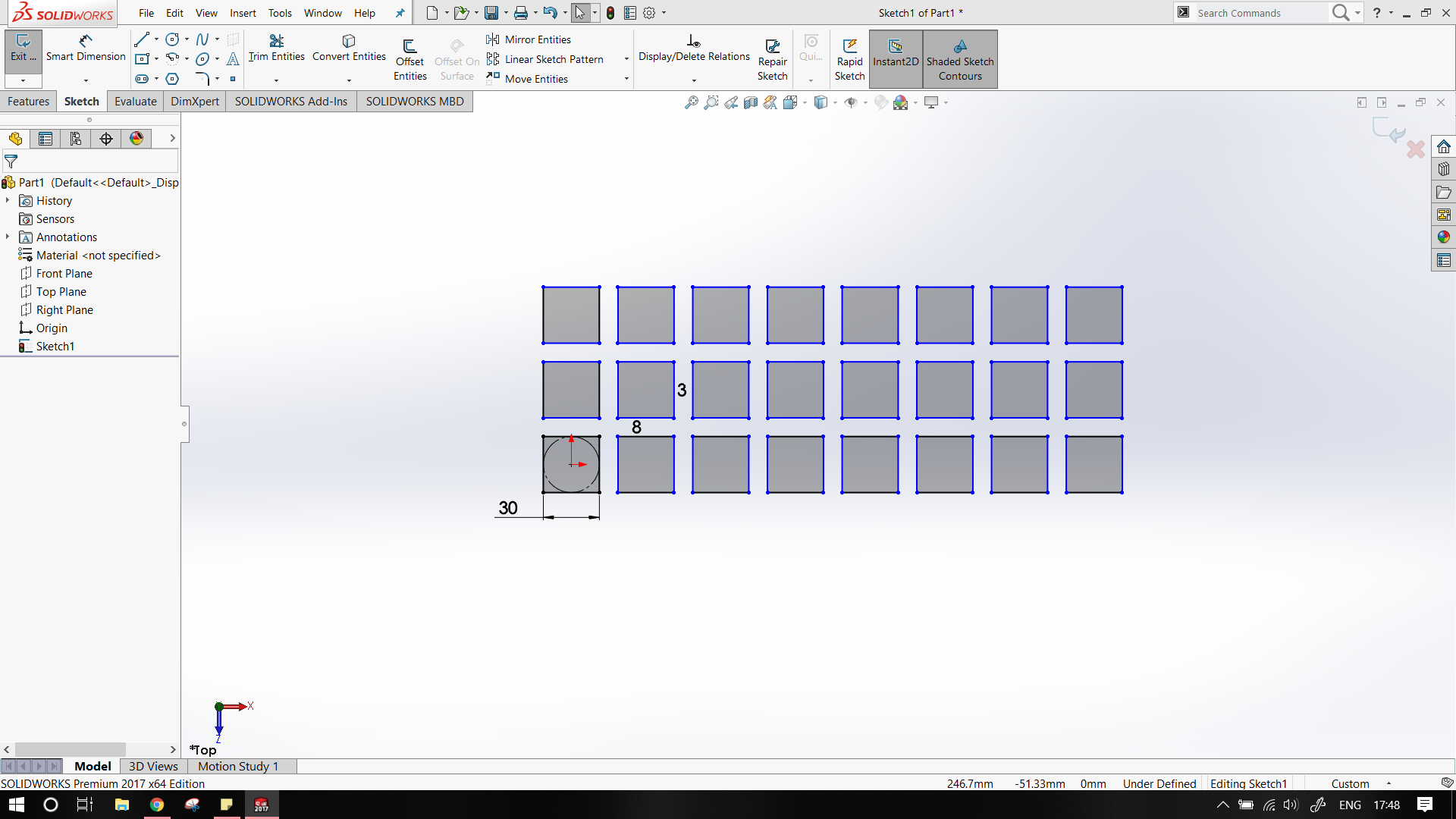
I made a simple 30x30mm square and using linear pattern I multiplied the pattern.
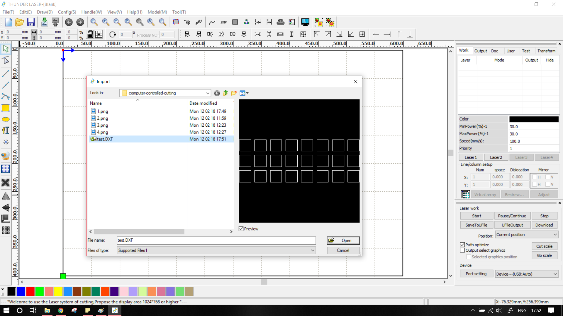
Sil is interfaced by RDworks v8 software. RDworks needs, works with dxf only, so we needed to export the file in dxf format. This can be done via
File -> Save As
Now select dxf from the drop down menu.
To import the file in RDworks
File -> Import
My local instructor suggested us that, 24 squares are overkill, So I reduced the number to only 4. The recommended values for power were around 65 and for speed was 23. I set the following values. I had some exprience hence I have selected the following values.
- Green : 67 - 28
- Blue : 64 - 22
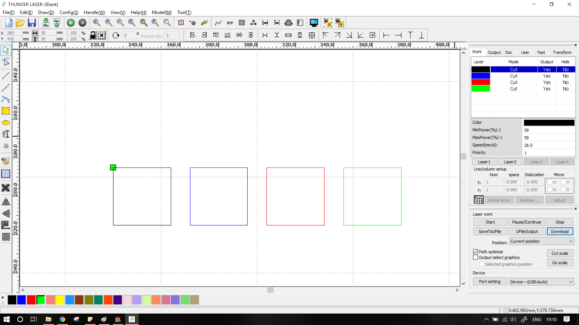
- Black : 59 - 26
- Red : 64 - 22
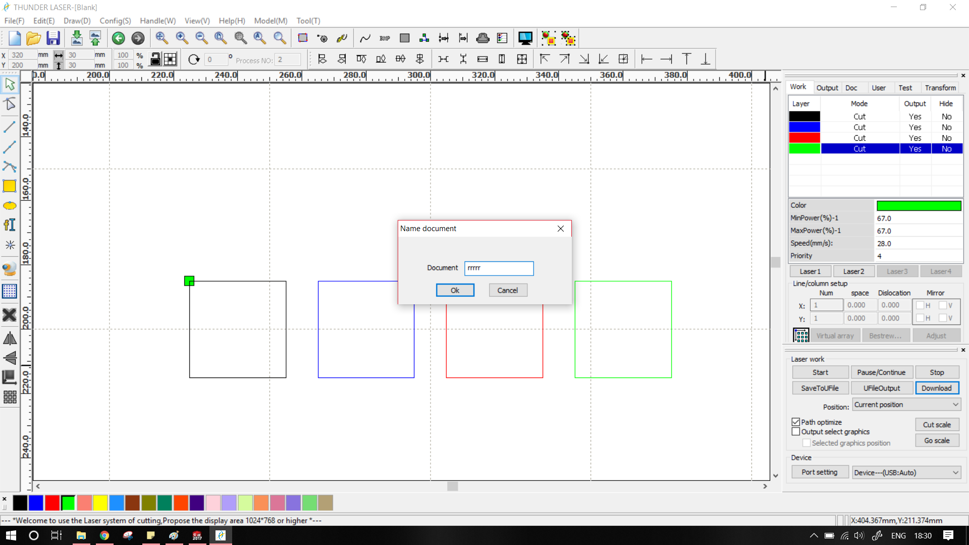
To cut the file, select the download button. The program will then as you to name the file.
We need to first adjust the focus of laser to for minimum kerf, and efficient cutting. Sil laser has manual focus adjustment. To do this we need to adjust the bed. The height of focus is ~8mm. To achieve we have pasted a 2.5mm MDF block over a 5.5mm acrylic block. Effectively giving the required focus.
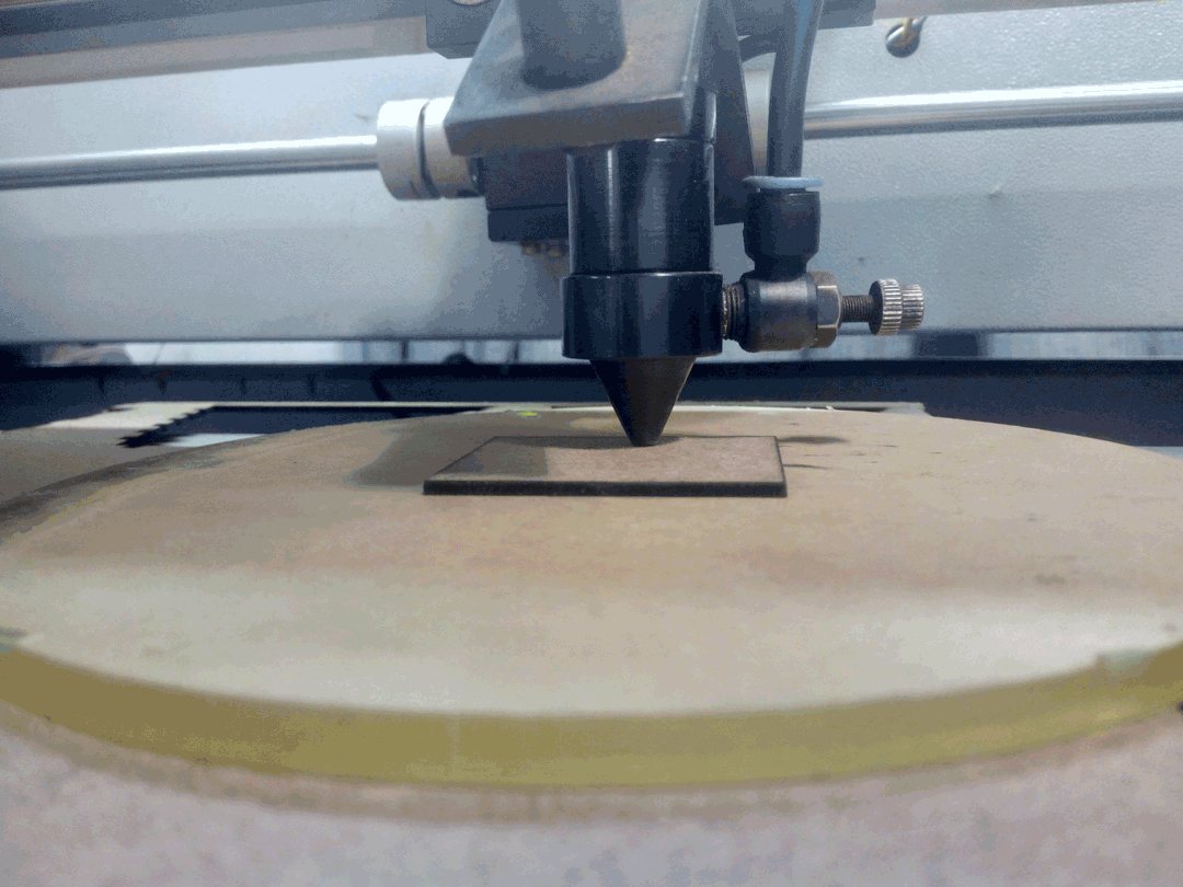
The most recent file sent by computer to the machine is available on the top, We now select the origin and frame the part. Framing is important as it gives an idea of the total area of the part.
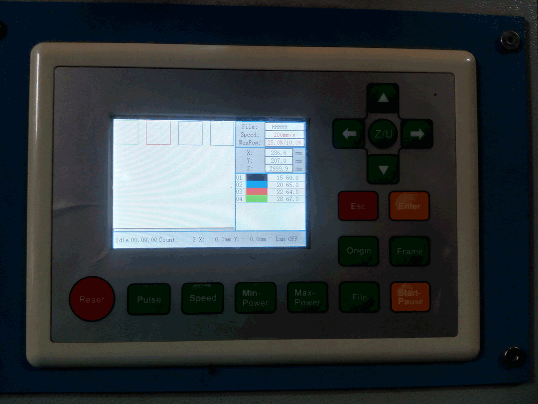
Press file
Select your file
Press Enter
Use the D-pad to ajust the laser in XY plane. Now press origin to set origin.
Press Frame
The laser will trace the file area. Check if there are no holes/missing parts in the area.
Press Start/Pause
The laser will now start cutting the file.
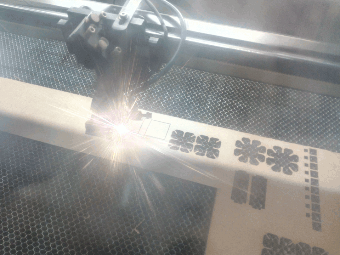
I had not engraved the parts with their names or unique identifiers... hence after cutting, labelled them with pen.
The next step is to take the parts individually, and calculate kerf.
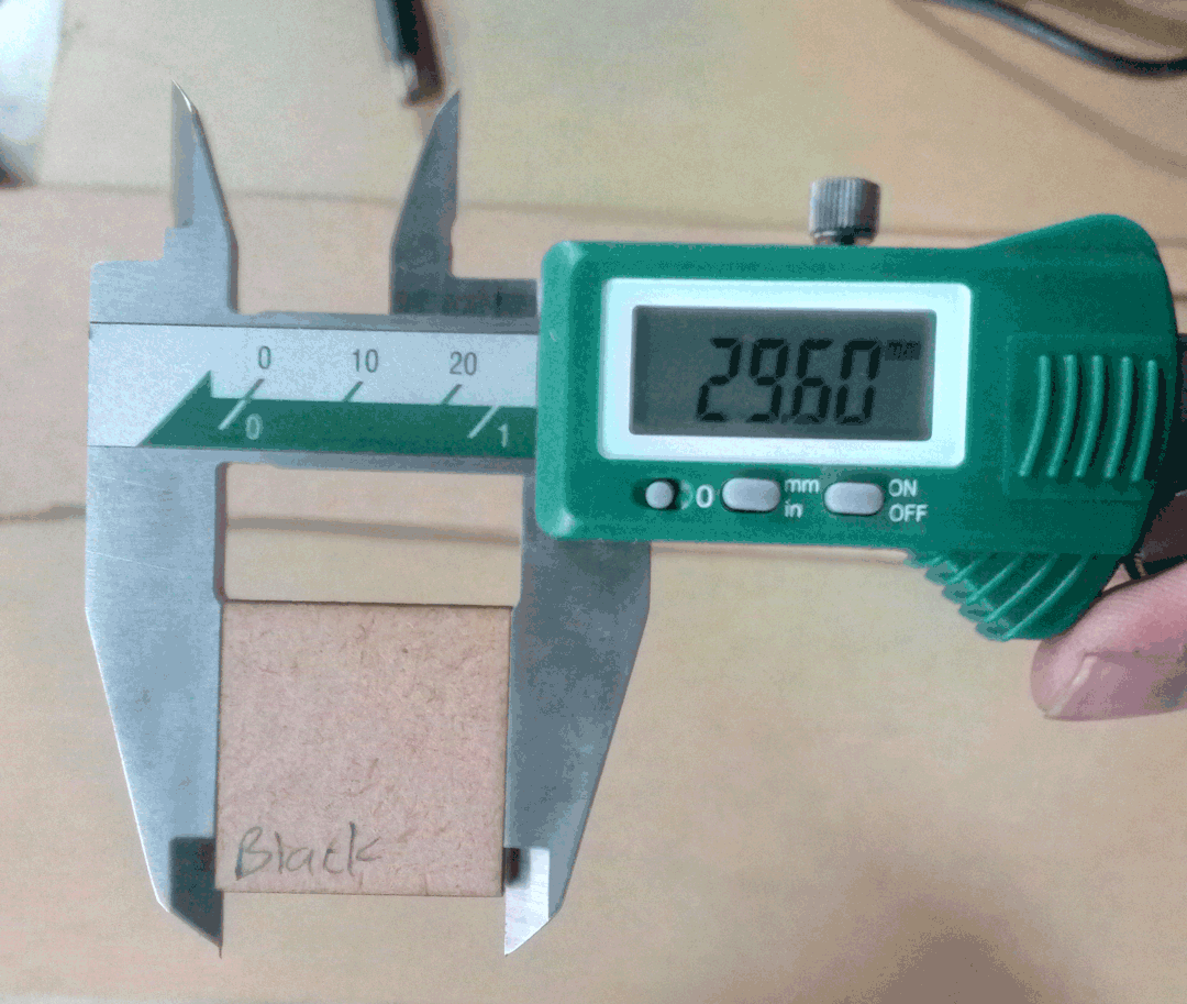
Funnily enough, there the kerf is different in both the axis. As seen in gif. The minimum kerf was obtained for BLACK.
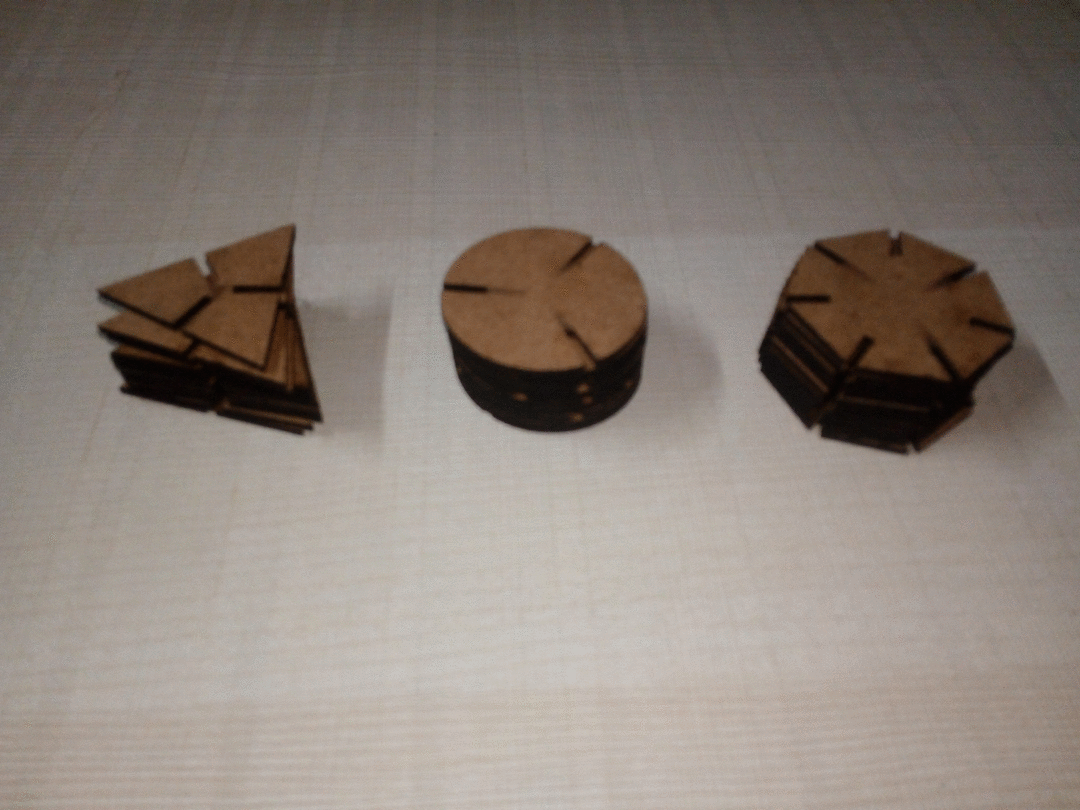
For my pressfit kit I decided to with heptagon, triangle and circle. The slot widths were 2.5mm
Rather than optimizing for kerf in Solidworks, I used RDworks to adjust the kerf.
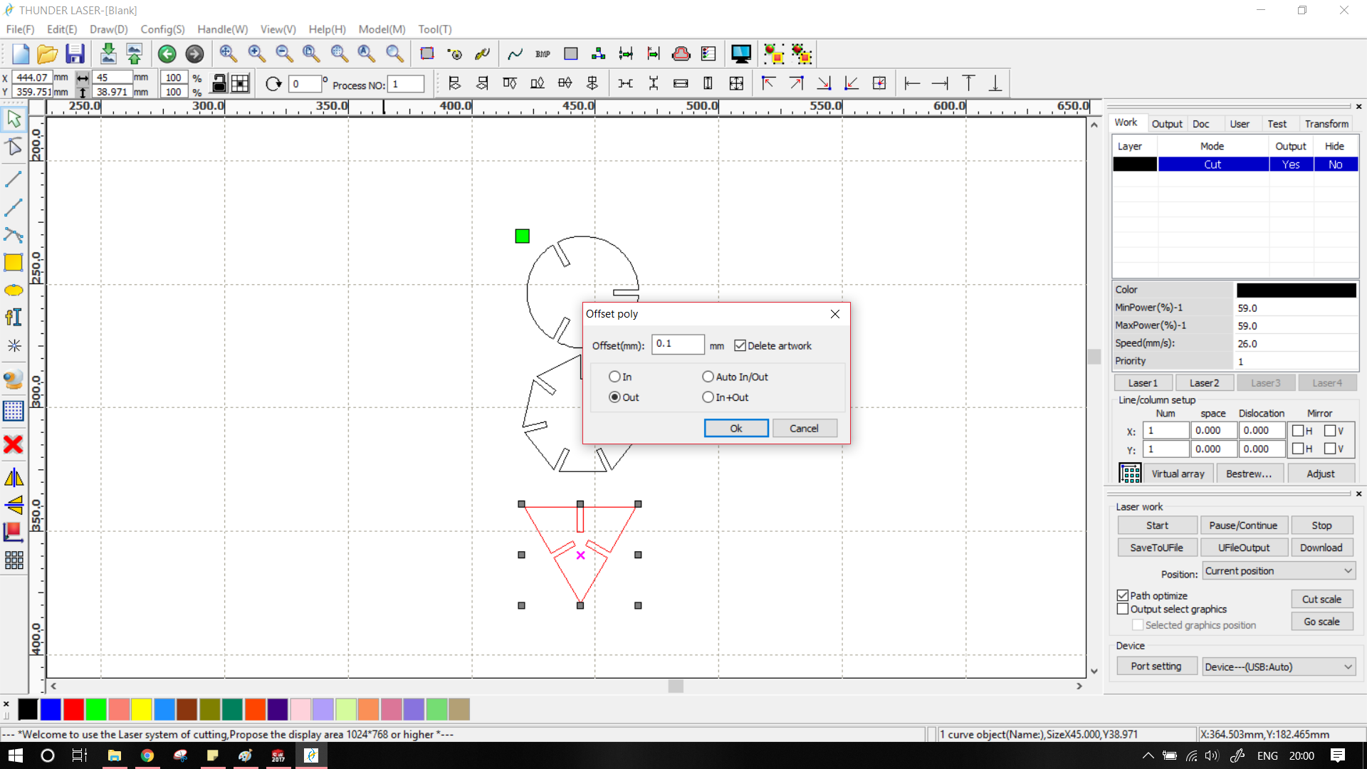
The joints still weren't pressfit. After a little bit thinking I found out the problem. I assumed that the MDF sheet had a thickness of 2.5mm, in reality the sheet was only 2.33mm thick. I changed the slot width to 2.33mm (and with the help of equations, in all the other parts/slots)
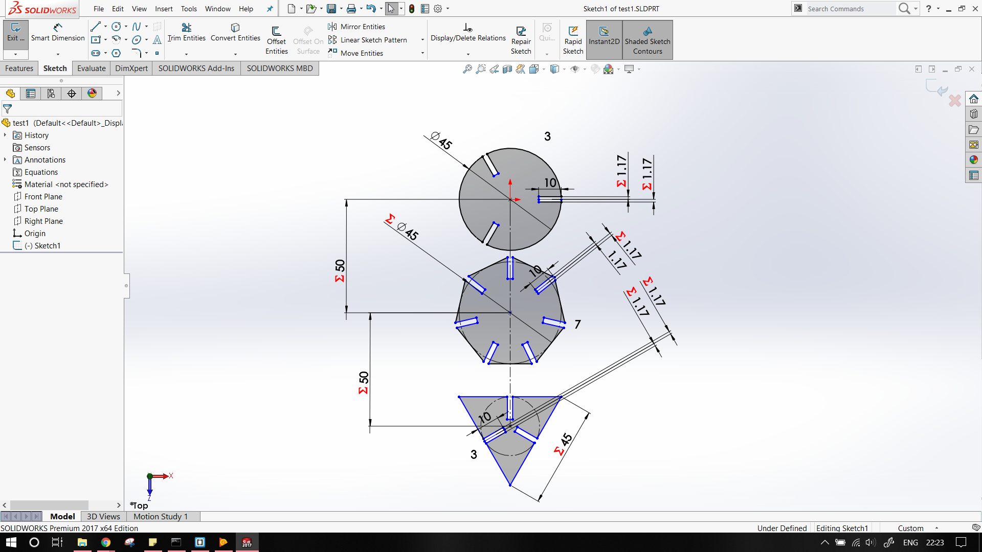
The output parts were a perfect fit!
The original files can be found here