Rohan Rege

Fab Lab Zero
Vigyan Ashram


<- Home


This week we had group assignment, this may cause the same image to appear on pages of multiple students

This week were tasked with:

  1: Group assignment:

   compare the performance and development work flows for other architectures

  2: Individual assignment:

Datasheets!

What is a data sheet? -  It is a document that summarizes the performance, technical and software characteristics in enough detail that anyone can integrate the component into a system.
It usually made by the component manufacturer.An electronic datasheet specifies characteristics in a formal structure that allows the information to be processed by a machine. Such machine readable descriptions can facilitate information retrieval, display, design, testing, interfacing, verification, and system discovery.


We have been using the Attiny processors from various boards till now. So for starters I decided to study the datasheet for attiny family. Before that, I wanted to do an complete overview of all the microcontrolers in the AVR family. I think this would help me choose my IC for the upcoming assignments.
A quick look on the google tells us -
The AVR family is classified as follows-
There are other ICs too like 32-bit (ARM compatible), AVR in LCD Display Drivers, USB Controllers.

I have used the Attiny 44A, in my hello-board.
The datasheet of Attiny 44A is available to download here.
The first page of the data sheet contains features of the datasheet.


To view the contents, press the bookmarks button, It will list out the contents of the pdf.


The pinout out diagram of the IC is also given. ATtiny44 is available in various configurations, PDIP (Platic Dual line In Package), SOIC (Small Outline Integrated Package), QFN (Quad Flat No leads), MLF (Micro lead Frame), VQFN (Very Thin Quad Flat No-lead). For our purpose we use the SOIC package. A detailed information about various packages is available here Except PDIP, all the other packages are SMD components.


The next important part is the pin description.
Each pin of the IC can have multiple uses. The pin description provides the use of each pin of the IC.


In my hello-board, I had connected the lED to the pin 6. This is actually PA-7 of the IC. PA-7 as the description suggests is a 8bit IO with internal pullup resistors. So instead of using pin 6. I might have to use PA-7 in my code.
The next part gives the block diagram of the IC.


The AVR core combines a rich instruction set with 32 general purpose working registers. All 32 registers are directly connected to the Arithmetic Logic Unit (ALU), allowing two independent registers to be accessed in one single instruction executed in one clock cycle. The resulting architecture is more code efficient while achieving throughputs up to ten times faster than conventional CISC microcontrollers.


From the 3.4 section we find that the data retention failure rate of attiny 44A is less than 1ppm over 100years at 25C.
Since fabacedamy is only for 6 months, I don't think we will be affected by this Also the AVR was created in ~1975 So the first programmed IC still has the code intact!!


Code Examples
  1. Embedded C
  2. In my Hello World Board, I have connected LED to PIN6 i.e. PA7. So first step is to define PA7 as digital Output. We modify to the data direction register (DDR) for this.
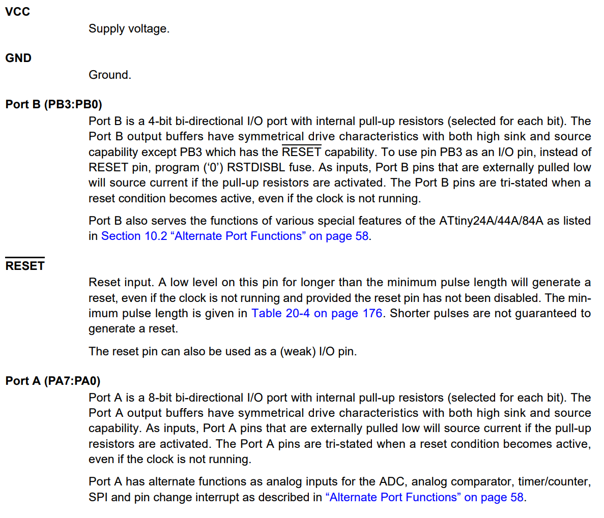
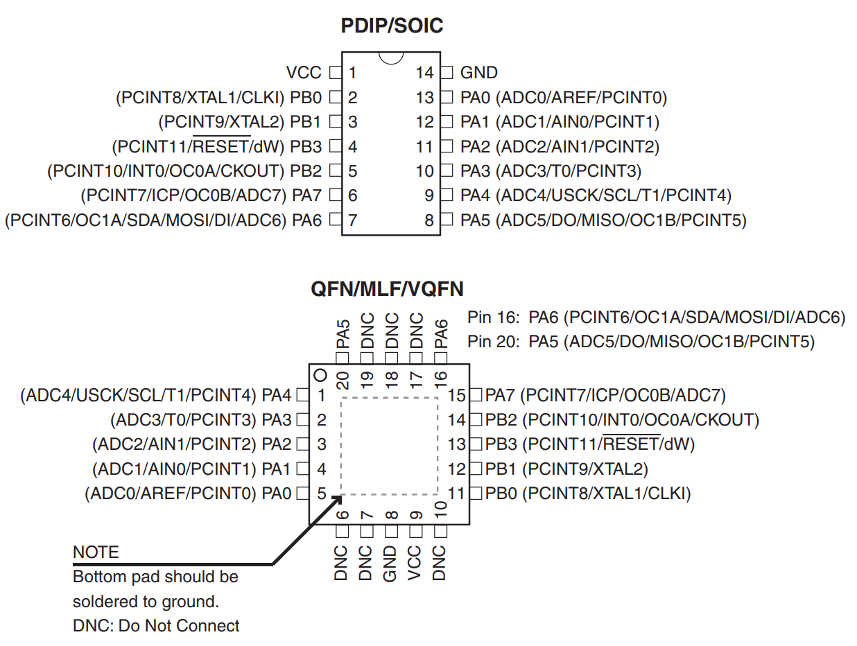
    The ATtiny 44 has 2 sets of these (PA and PB). For port A (PA0-PA7) we use the DDRA command.
    To set all pins of PORT A as output we should write : DDRA =0xFF or DDRA =0b11111111. Where: To set any port as high we write PORTA |= (1<<7) or PORTA |= (0b10000000)
    To set any port as low we write PORTA |= PORTA &= ~(1<<7) or PORTA &= ~(0b10000000)

    /*
    * led_blink.c
    *
    * Rohan Rege
    *
    */

    #define F_CPU 20000000 //Define clcok speed as 20Mhz
    #include <avr/io.h> //Import header file required for AVR microcontrollers
    #include <util/delay.h> //Import header flie required for delay function
    int main(void)
    {
    DDRA = 0b10000000; //set PA7 as output
    while (1) //Infinite Loop
    {
    PORTA |= (1<<7); // Set PA7 high (Make LED ON)
    _delay_ms(5000); //delay of 5 sec
    PORTA &= ~(1<<7); // Set PA7 low (Make LED OFF)
    _delay_ms(5000); //delay of 5 sec
    }
    }


    To flash this program, I've used Atmel Studio on windows.
    Download and install atmel studio the go to file -> New -> Project


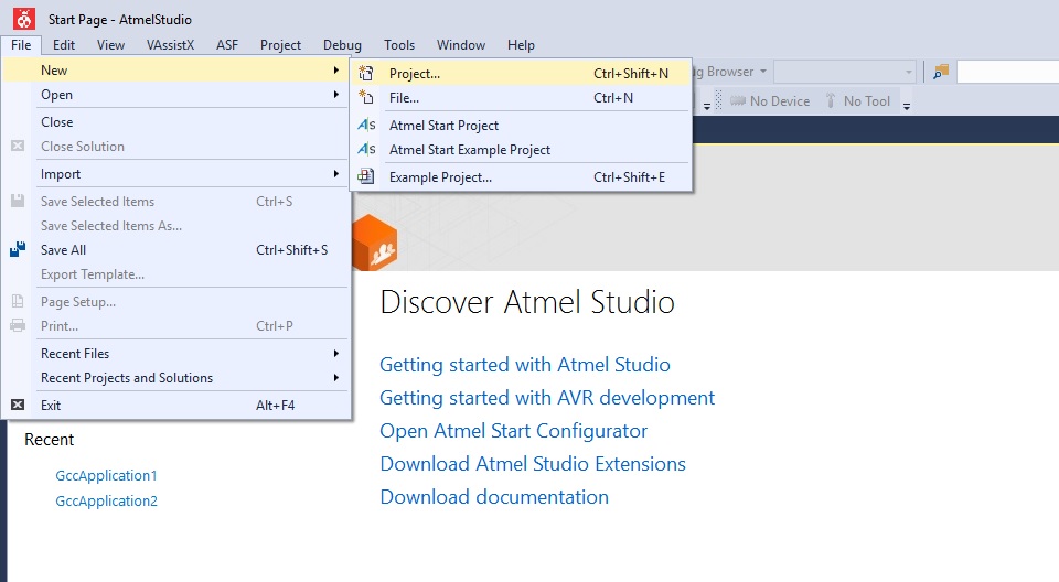
    Then select the second option in GCC Executable Project C/C++
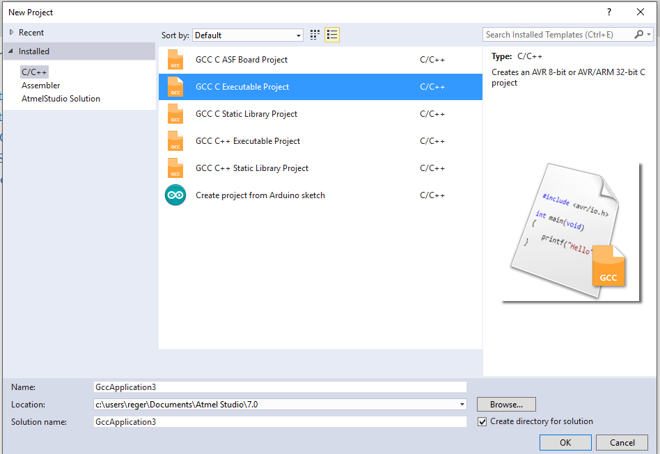
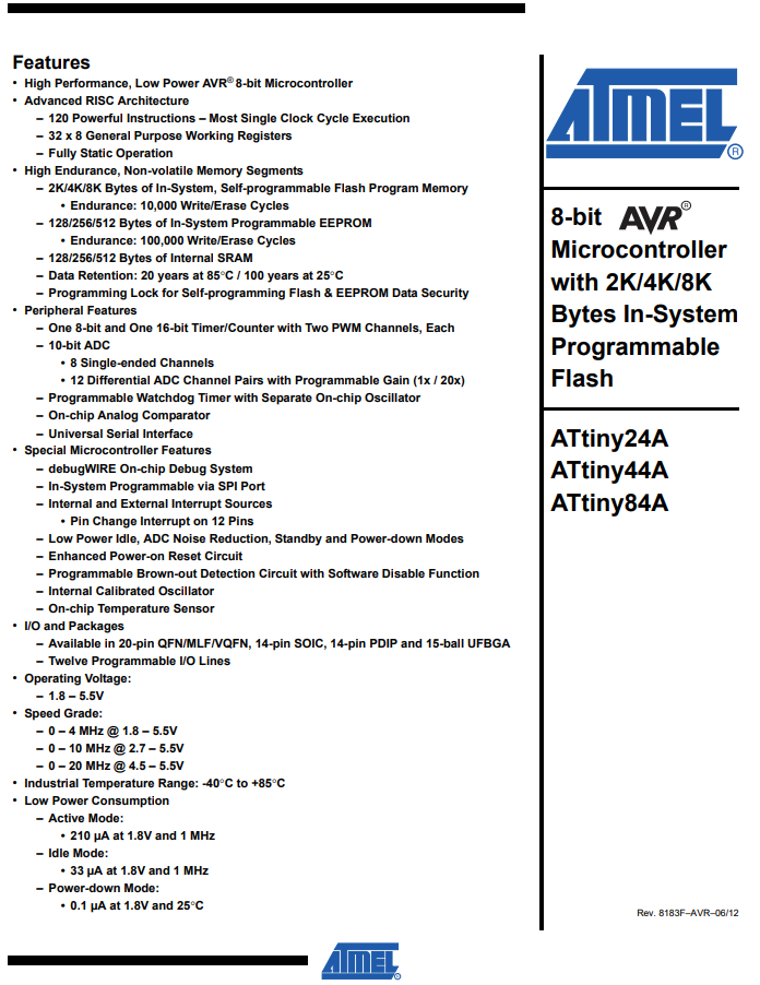
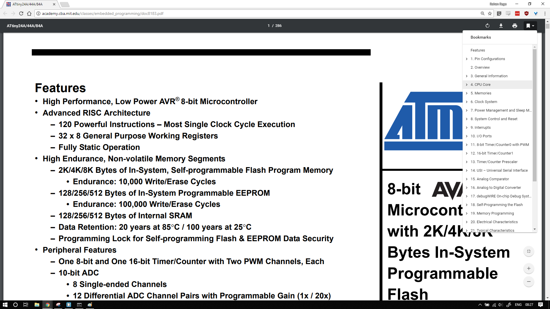
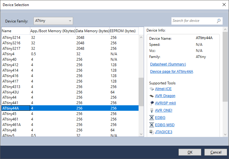


    Then select the IC


    Then copy the above program in the file


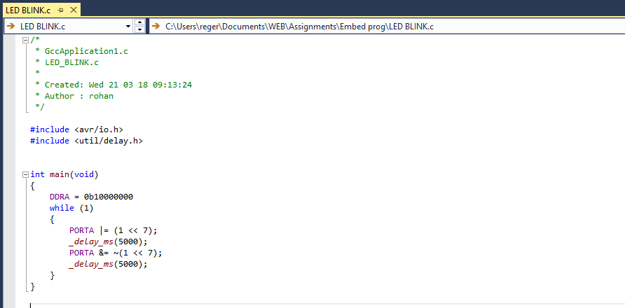
    Save the file and click on build project
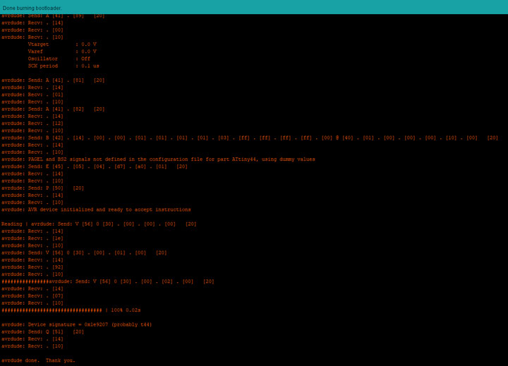
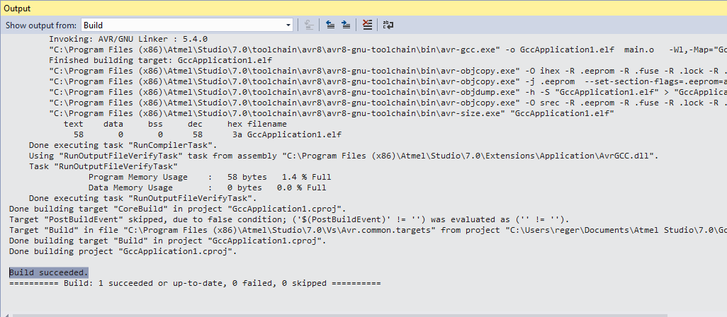
    The output of the build should look like this


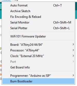
    To program by the USB tiny we need to set it up.
    To do that add it to the external devices of the atmel


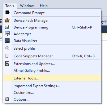
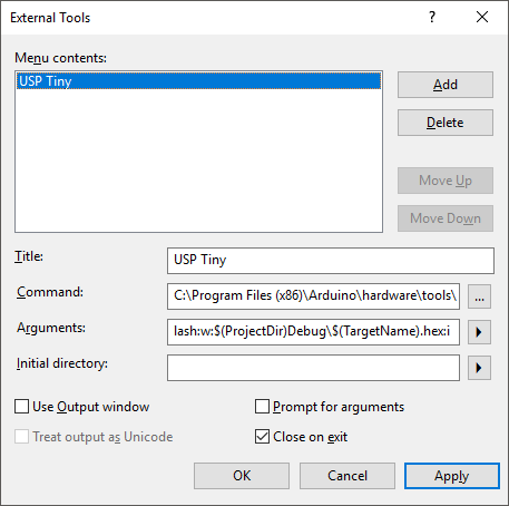
    Then build the again go to external tools and select the TINYUSB


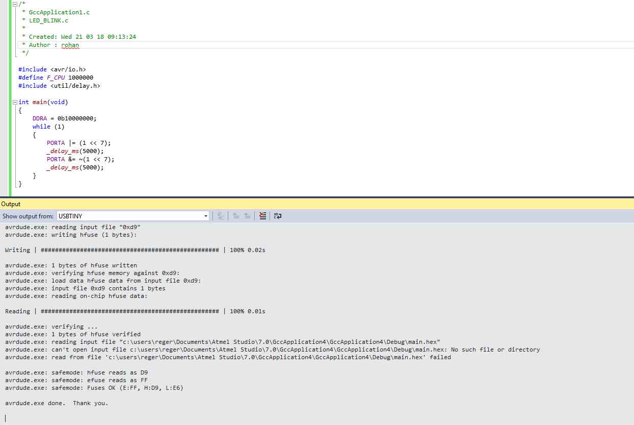
    This output looks like this:


  3. Assembly

  4. Assembly is a lower level language than Python and Embedded C.
    Assembly language is an alphanumeric representation of machine code. Below is an example of a AVR assembly code written in assembly language. Each line of the code is an instruction telling the micro controller to carry out a task.
                ADD     R16, R17       ; Add value in R16 to value in R17
                DEC     R17            ; Minus 1 from the value contained in R17
                MOV     R18, R16       ; Copy the value in R16 to R18
    END:        JMP     END            ; Jump to the label END


    I have used the cbi and sbi to directly modify the registers.
    The code is sourced from here

    .device attiny44

    .org 0
    sbi DDRA,0

    loop:
        sbi PORTA,0
        cbi PORTA,0
    rjmp loop


    I was going to try and follow the tutorial by Steven Chew to program IC in assembly.
    But the it proved too challenging for me.
    Also I could not justify the time required to program in assembly.

    I'll not do anything that I don't understand hence I will not program this.


  5. Arduino based C/C++

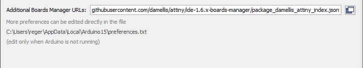
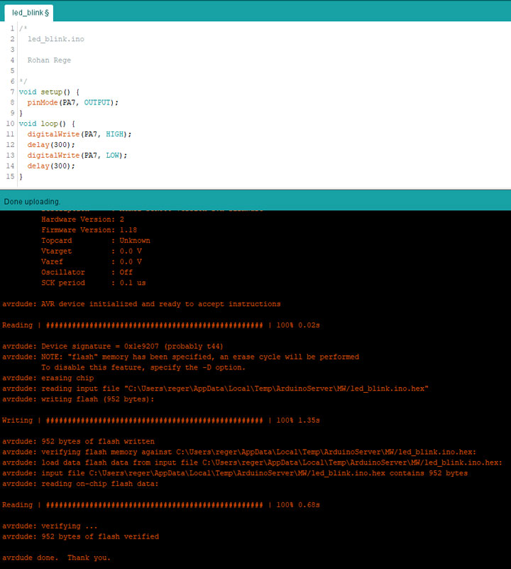
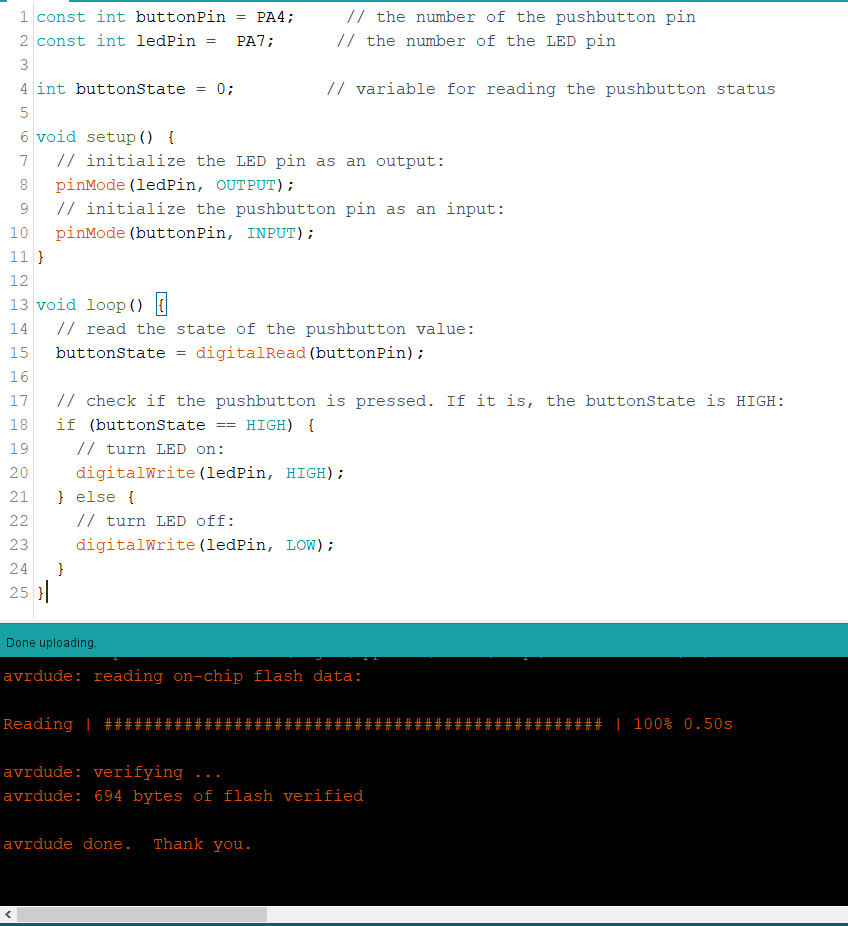
  6. The arduino language is really great for beginners, but have some limitations (e.g. you must have all your files in the same folder). And it is basically a simplification of C/C++ (you can practically copy & paste arduino code to a C/C++ file, and it will work). Also it makes sense that you can go and use a full well known IDE as eclipse if you are experienced

    /*

    led_blink.ino

    Rohan Rege

    */

    void setup() {
     pinMode(PA7, OUTPUT);
    }
    void loop() {
     digitalWrite(PA7, HIGH);
     delay(300);
     digitalWrite(PA7, LOW);
     delay(300);
    }
By default we don't have Attiny 44 as in the boards list in arduino editor. We need to add it.
A tutorial is given by the people at highlow tech here. They have made custom libraries, hardware support packages for almost all the ATtiny series.
Now flash the ArduinoISP code from examples to the board
Connect pins as follows:


Now the flash the bootloader, by selecting the following settings


You'll get something like this


Now you are free to burn your program on the chip


The output looks like this:


As requested, I've also wrote a program for led ON/OFF controlled by the button.
To to this, I had to added a jumper from the Button to the PA4 of the IC.


I've flashed it using Arduino As ISP.


The output looks as follows:


Group Assignment:

For this week we have to understand the Architecture of the board. We had decided to explore the architecture, configuration and coding it through python.


Specification:
  • CHIP- Broadcom BCM2835 SoC
  • Core Architecture- ARM11
  • CPU- 700 MHz Low Power ARM1176JZFS
  • GPU- Dual Core VideoCore IV® Multimedia Co-Processor
  • Memory- 512MB SDRAM
  • Operating system- Boots from Micro SD card, running a version of the Linux operating system
  • Dimension- 85 x 56 x 17mm
  • Power- Micro USB socket 5V, 2A

  • Comparing architectures: I decided to write a simple code in python to blink LEDS.
    import GPIO as g          #importing the general purpose input/output pin control library and renaming it as 'g'
    import time          #importing the time library

    g.setmode(g.BCM)         #setting the pin layout based on BCM rather than normal numbering
    g.setup(18 , g.out)         #defining the output pin
    print "led On"         #Printing the LED ON in terminal
    g.output(18 , g.HIGH)         #Turning the output HIGH
    time.sleep(1)         #Sleeping for 1s
    print "led Off"         #Printing led off on screen
    g.output(18 , g.LOW)         #turning the output LOW

    The above will only work once, so I added a while loop and if statement

    import GPIO as GPIO
    import time

    GPIO.setmode(GPIO.BCM)
    GPIO.setup(11, GPIO.OUT)
    GPIO.setup(13, GPIO.IN)
    while True:
      if(GPIO.input(13)):
        GPIO.output(11, True)
        time.sleep(0.1)
        GPIO.output(11, False)
        time.sleep(0.1)


    We wrote a test program for blinking the LED, when one pin if one Pin is HIGH, in the local text editor. The code is as shown below:


    We connected our LED to GPIO pin of the board on the bread board.Then check the pin in a code which we connected on the board and write the correct pin number in a code...


    Then we run the program and get the output (see below:)