Rohan Rege
Fab Lab Zero
Vigyan Ashram
<- Home
This week we had group assignment, this may cause the same image to appear on pages of multiple students
We are using the old version of FAB modules. Although the newer mods are better, it takes more steps to accomplish the same task when compared with the older modules
This week were tasked with:
1: Group assignment:
measure the analog levels and digital signals in an input device
2: Individual assignment:
measure something: add a sensor to a microcontroller board that you have designed and read it
Wew! What a roller coaster it was!
This week we had to measure something (sense something).
I plan to use only 1 sensor,
LM35
Although, both DHT and LM35 give temp, LM35 is analogue (output) and DHT is Digital (Output). I was planning to use Attiny44 and just modify the design for my helloworld board.
Attiny 44 has 12 I/O pins PA(0-5) and PB(0-5). It seems like overkill. Most of the pins would remain unused. Hence I decided to go with attiny 45.
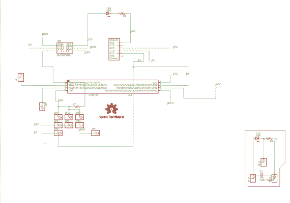
Taking inspiration from the helloworld board, I attached LEDs to Rest and GND in my schematic.
Big mistake.
This caused many issues with routing. Even my tried and tested formula of auto route + manual edits did not work. I could have used 0Ohms resistor to jump over connections but thought against it. My boards are too simple to use them. After spending a good 0.5 days, I was able to crack it. I modified a few things.
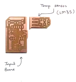
Made separate boards for micro controller and sensor.
This enables me to use my reuse my board.
Instead of putting headers only on the used pins, I put the headers on all the pins.
My little arduino clone but with ATtiny45.
Removed led between RST and GND and added it between +Vcc and GND.
Removed capacitor from the main board and put it on the the sensor module board I made.
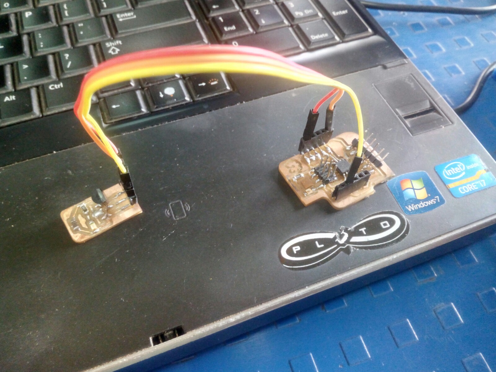
So now basically have had 2 boards.
1 for sensor and 1 main board.
I plan to join these with ribbon cables or Jumper cables.. thats undecided.
i was able to route the boards easily this time
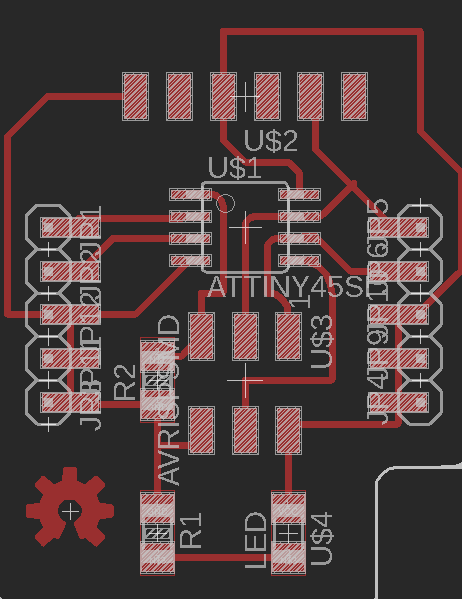
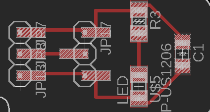
The traces of the board:
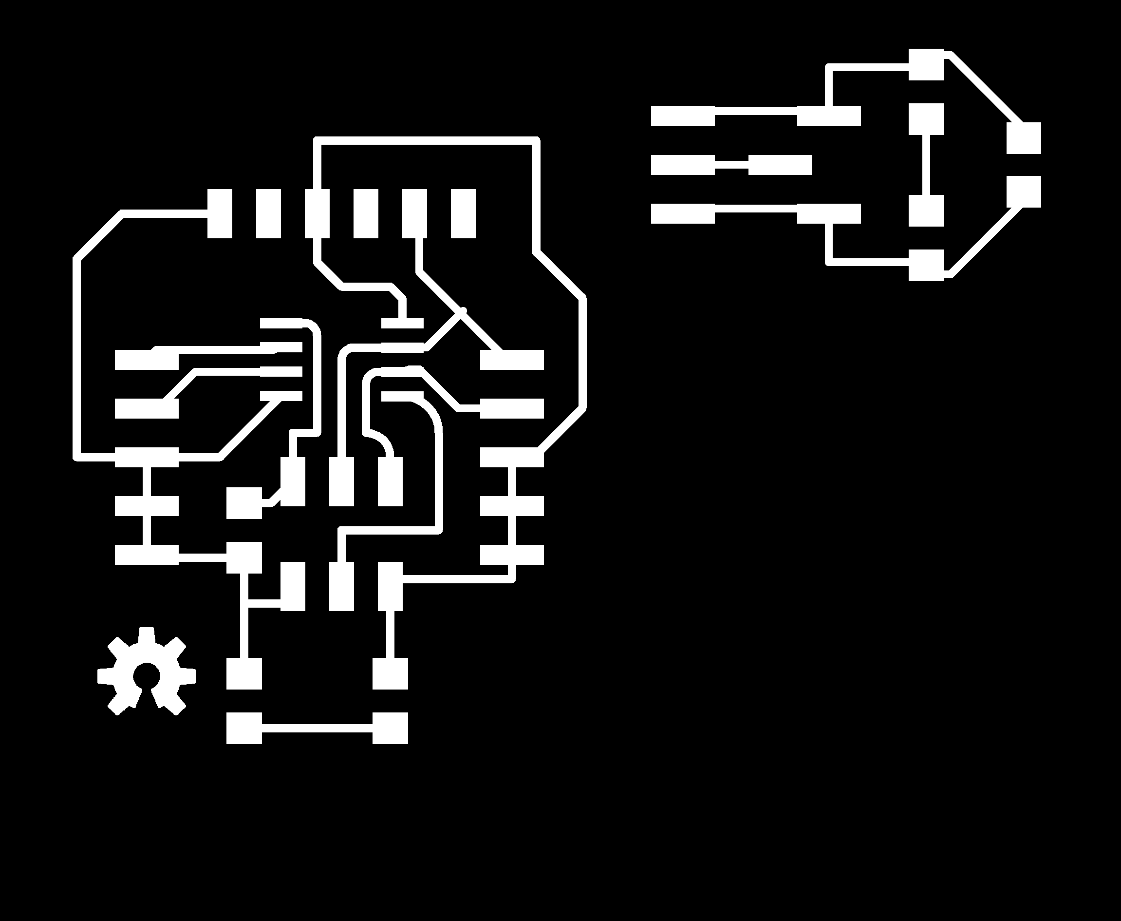
The cutout of the board:

The BRD files are available here and the SCH file is available here
Till the boards were milling, I decided to check with the LM35.
LM35
It looks like a big transistor, but they can (and are) deceiving. Its the new one of the bunch. LM35 is a temperature sensor with analogue type output. LM35 series are precision integrated-circuit temperature devices with an output voltage linearly proportional to the Centigrade temperature.
A quick look at the data sheet gave me the pinout and the correct way to join it.
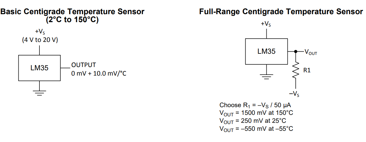
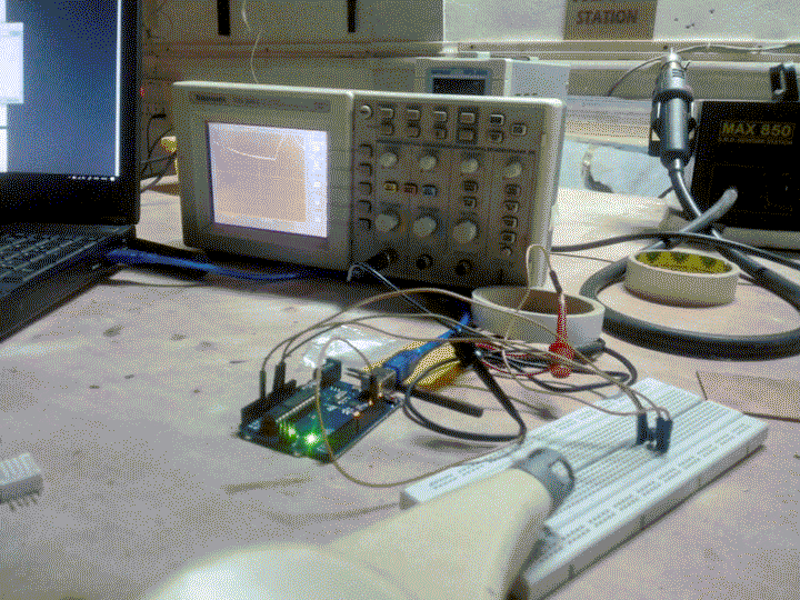
Full range sesnor does look tempting but it would mean passing -5v volts, and that night I decided to go against that notion. I placed it on the board and fired up and arduino. connected to the breadboard.
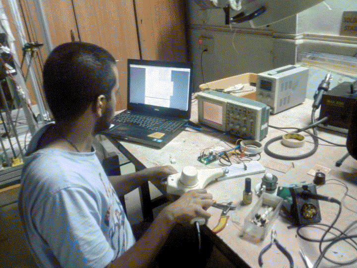
Initially I just to see the output, I simply read the output on the CRO, after adjusting the volts/div and increasing the time duration to around 2-10secs I was able to observe the output.
This will basically help me understand how I should write the code.
I used a heat gun to test the rise in temperature.
After that I modified the program and added DHT22 sensor, but the value shown on the Arduino IDE Serial monitor was 1023. At this time I didn't knew that DHT22 gave digital output or that it could be read only 1 times every 2 second. Reading the Datasheet first could have saved me sometime.
On a side note, DHT22 datasheet is one of my least favorites.
Luckily lady Ada came to the rescue and I used her code and libraries.!!
I simply modified the code little and added support for lm35.
My code (lady ada's code + my bits ) can be seen here (raw file)
With this code I was able to get temps from LM35 and DHT22 and humidity from DHT22.
LED as Input
I had read somewhere that theoretically, a speaker can work as a microphone so using that analogy a LED should be able to work as a photo diode. I had articles about this before on makezine here
I did a bit googling on this, and luckily someone had already done it and uploaded code to arduino playground.
I wanted to try this also, to do this i used a simply uploaded the program to arduino UNo and connected the LED and resistor as mentioned in the code.
Connect a 100 Ohm resistor between cathode and Digital Pin 2,
Connect the anode to the digital pin 3.
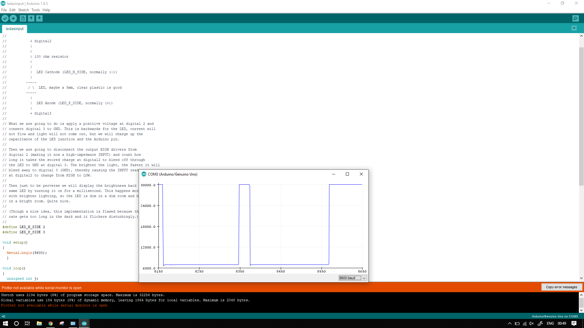
Then just to be perverse we will display the brightness back on the same LED by turning it on for a millisecond. This happens more often with brighter lighting, so the LED is dim in a dim room and brighter in a bright room. Quite nice.
I modified the just a little bit so as to obtain the serial values of the data.
I used a baud rate of 9600, the detailed code is available to download here
The raw ouput of serial data, is in the image below
The next step is to take readings on my micro controller board
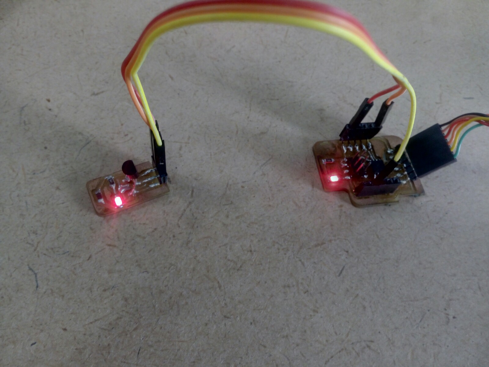
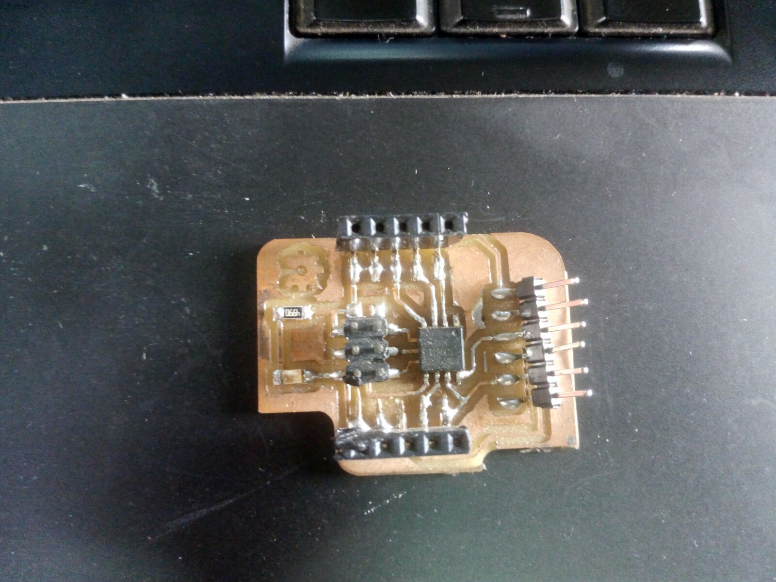
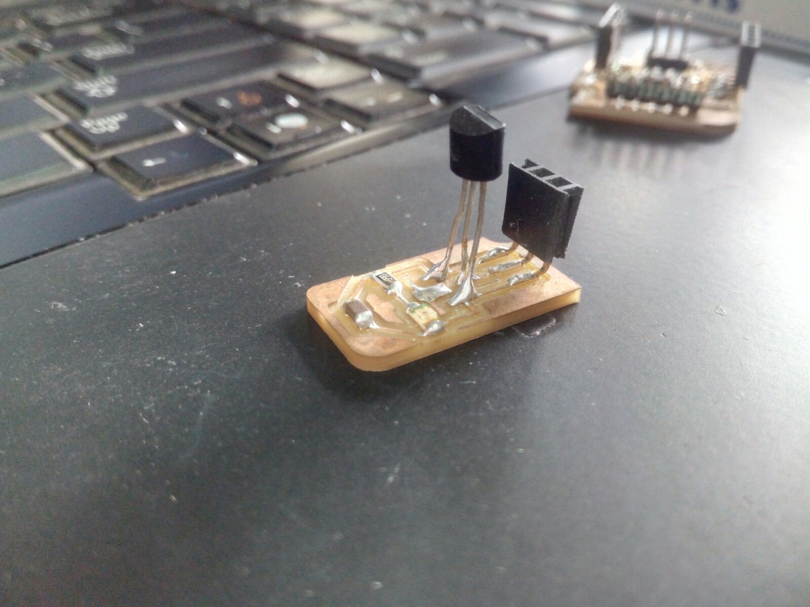
I millied my micro controller and one module for LM35
After soldering the boards look like this,
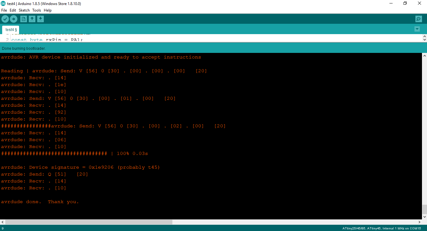
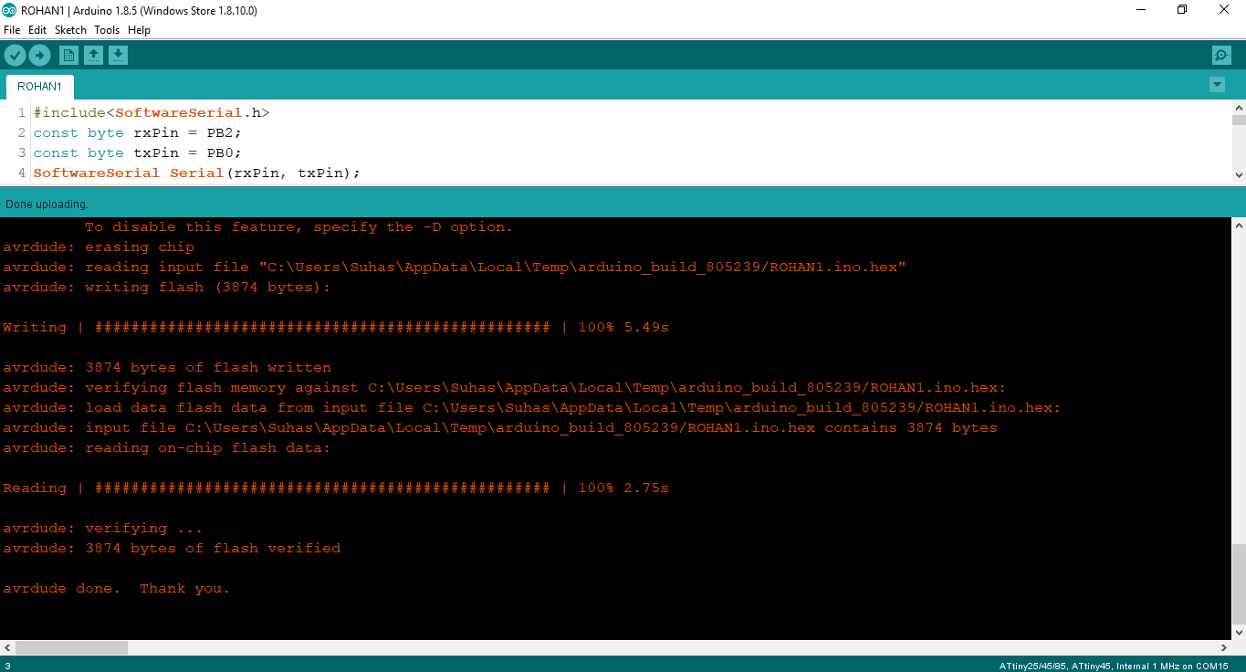
Next thing I did was to burn the boot loader on the IC
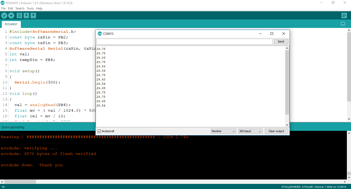
Then I flashed the program on the IC, My program is loosely based on the one available from Arduino Playground, except mine is for Attiny45.
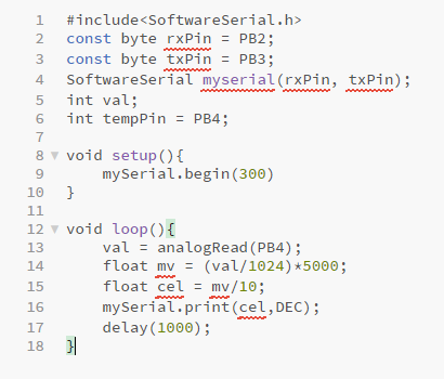
The code inputs the data from the LM35 as raw then converts it into digital format by the dividing the by 1024 (max value) and then multiplying by voltage (millivolts)
We then divide this 'mv' by 10 as LM35 increases by 1°C per 10mv.
Which then passed to the serial.
I then connected the FTDI cable to the board and it was assigned COM13 by the machine