Rohan Rege
Fab Lab Zero
Vigyan Ashram
<- Home
This week were tasked with:
1: Group assignment:
- actuate and automate your machine
- document the group project and your individual contribution
I'll be honest this part is way beyond my league.
So this week I was in autopilot.
Arefin and Rutvij took the lead as they worked with interfacing and eletronics of the machine.
Unlike previous years, this time the machine week was much later than before, hence Input, Output and interfacing weeks had already been completed
This gave me a better chance to further understand what Arefin and Rutvij were doing.
My primary focus this week was to make arm in acryllic and be ready when the eletronics part is done.
Being mechanical I cannot wholly ignore the electronics part of the arm, as it contains the kinematics.
For robots like the 3D arm, kinematics are an integral part.
Kinematics:
Kinematics is a branch of classical mechanics that describes the motion of points, bodies (objects), and systems of bodies (groups of objects) without considering the mass of each or the forces that caused the motion.
Kinematics can be further separated into two major parts:
- Forward Kinematics
- Reverse Kinematics
Forward Kinematic, or the easier of the two.... they give the position of the end effector based on the individual relative position of the joints.
Reverse Kinematics, or the harder of the two... they give the relative position of the joints based on the position of the end effector
The robot’s arm must adjust each joint’s angle in order to move its hand over to the position.
This is quite the opposite - here, we start with a given position and want to know how to rotate each segment of the arm.
It turns out that this is much harder than the forward case. And whenever something is hard to solve, there are usually several different approaches available for solving that problem. For inverse kinematics, there are three of them:
- The algebraic approach: This basically works by solving (frankly, rather complex) matrix equations.
- The geometric approach: The idea is to combine knowledge about the robotic arm’s geometry with suitable trigonometric formulas.
- The numeric approach: Take a guess and look how far we are off. Move one or more segments to locally minimize the error. Repeat.
I did a rough calculation of the kinematics, to solve the reverse kinematics we need t=to calculate the D-H parameters, i.e. the Denavit–Hartenberg parameters
I suggest going through this video to get a more clear understanding of the D-H parameters
Below is the D-H parameters reference frame layout of the our arm
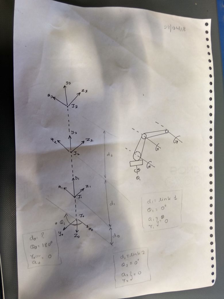
The method is consider the Z axis as the axis of rotation of actuator
and then place the X and Y axis as per the required,
There are many interfacing techniques that I came to know while working on the arm.
I haven't worked on them, but I learned a great deal from Arefin
Initially, we had decided to make the electronics part ready, while the arm was being built.
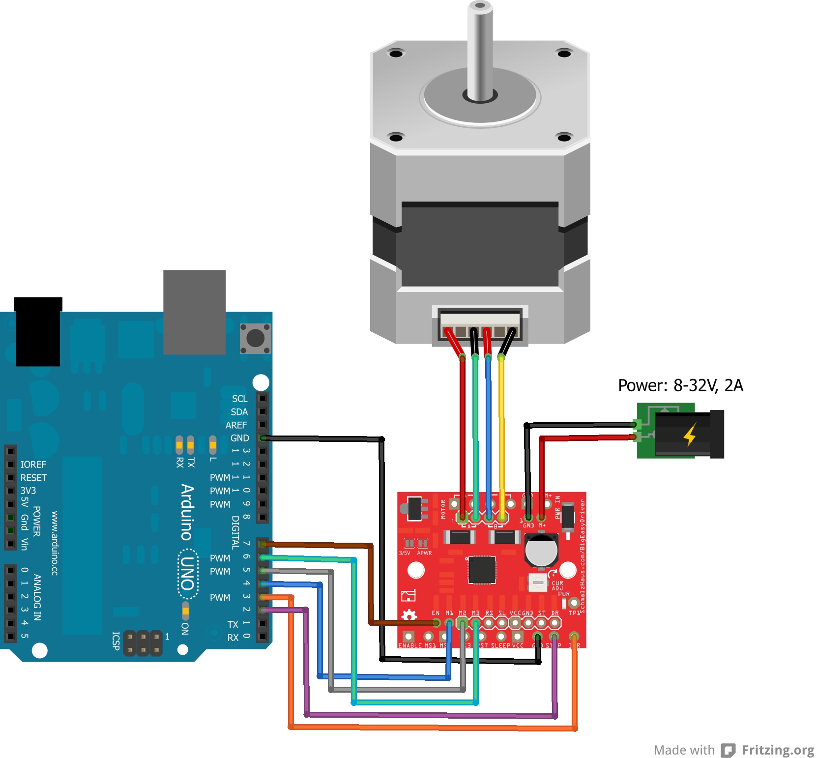
For this we testing if the motors that we have at our disposal are working, and if they are working how do we control them?
We searched online and found this tutorial
Also I found that we some stepper motors have more wires than others
Its was very confusing.
I again searched the internet and found LEAD WIRE code for stepper motors

Out of the 6 motors given to us, we found that 3 of them were defective.
Luckily we only needed 3 for our arm
Later Arefin came to know that the easystepper driver would not be able to provide enough current to drive the motors so we shifted to TB6600 motor driver and for the CPU we used RAMPS 1.4
It was now discovered that, that the motors that we considering as NEMA 34 (equivalent) were actually lower grade motors NEMA 24 (equivalent) would not have enough torque to to hold the arm
So, modified the arm design yet again, this time I took inspiration from MeARM.
MeARM uses a simple triangular shaped link to hold the end effector parallel to the ground.
I studied the design, and reversed engineered it.
MeARM uses a isosceles triangle based link, I designed a similar link but I have calculated for equilateral triangle
I've also allowed the link mechanism to be anchored freely so that we can adjust the position of the end effector with respect to the ground.
This design was finally lasercut on acryllic, the based was made from acryllic and metal, it was fabricated at Chaityana's workshop
The project page for arm can be found here
The files for arm can be downloaded here