This week we had group assignment, this may cause the same image to appear on pages of multiple students
This week were tasked with:
1: Group assignment:
communicate between two boards.
2: Individual assignment:
design and build a wired &/or wireless network connecting at least two processors.
This week I as very busy. Firstly I had forgotten some part of my inventory. So I had to go back to Pune to get it.
Also this week, I had to go my college. During the last two years in my college I was part of the SAE collegiate club.
This year we have taken part in SAE Supra India.
We were going to unveil the car. I also had to do a Bank job, :P
Anyways I was in pune for a good amount of time.
So I did not had much time to work on my assignmment this week.
I decided to do a simple synchronous transfer.
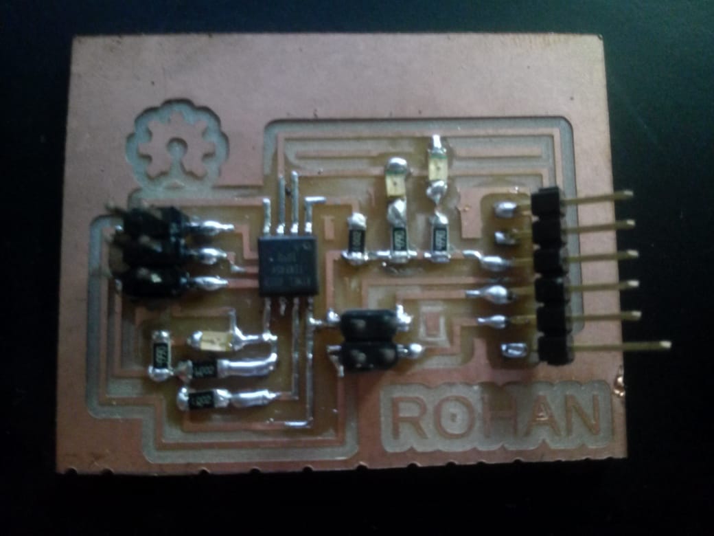
I also tried making flexible PCBs with Cu rolls.
Last time we tried it. The epoxy roll was not adhering properly to the copper. This caused the traces rip. This time we used an OHP sheet and used double sided tape to adhere it.
It worked for a trial batch.
We then decided to use the this.
Some notes regarding using of vinyl cutter with OHP sheets.
Try to make traces which are parallel and perpendicular to the XY axis.
Slant traces were prone to ripping.
Do't use set the temperature of the solder iron very high while soldering
Very high temperature nullifies the effect of glue. Also Very high temp can create holes in the PCB.
Don't use acteone to clean the surface.
;Acetone dissolves the adhesive.
Group Assignment:
I2C
We used Neils' code on my board. For Async, I connected the Pin headers to the respective connections.
Code is available here
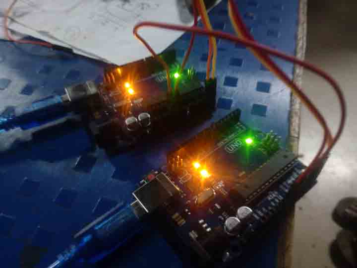
In the video above, I have used one of my board as bridge board and the one of Arefins' board as node board.
The FTDI cable is used to with Arduino serial monitor to send signals.
Individual Assignment:
Instead of making two different boards (master and slave) I decided to make two similar boards (master).
I plan to use one board as master and one board as slave.
By giving each board AVR ISP header, I can use them I2C communication also.
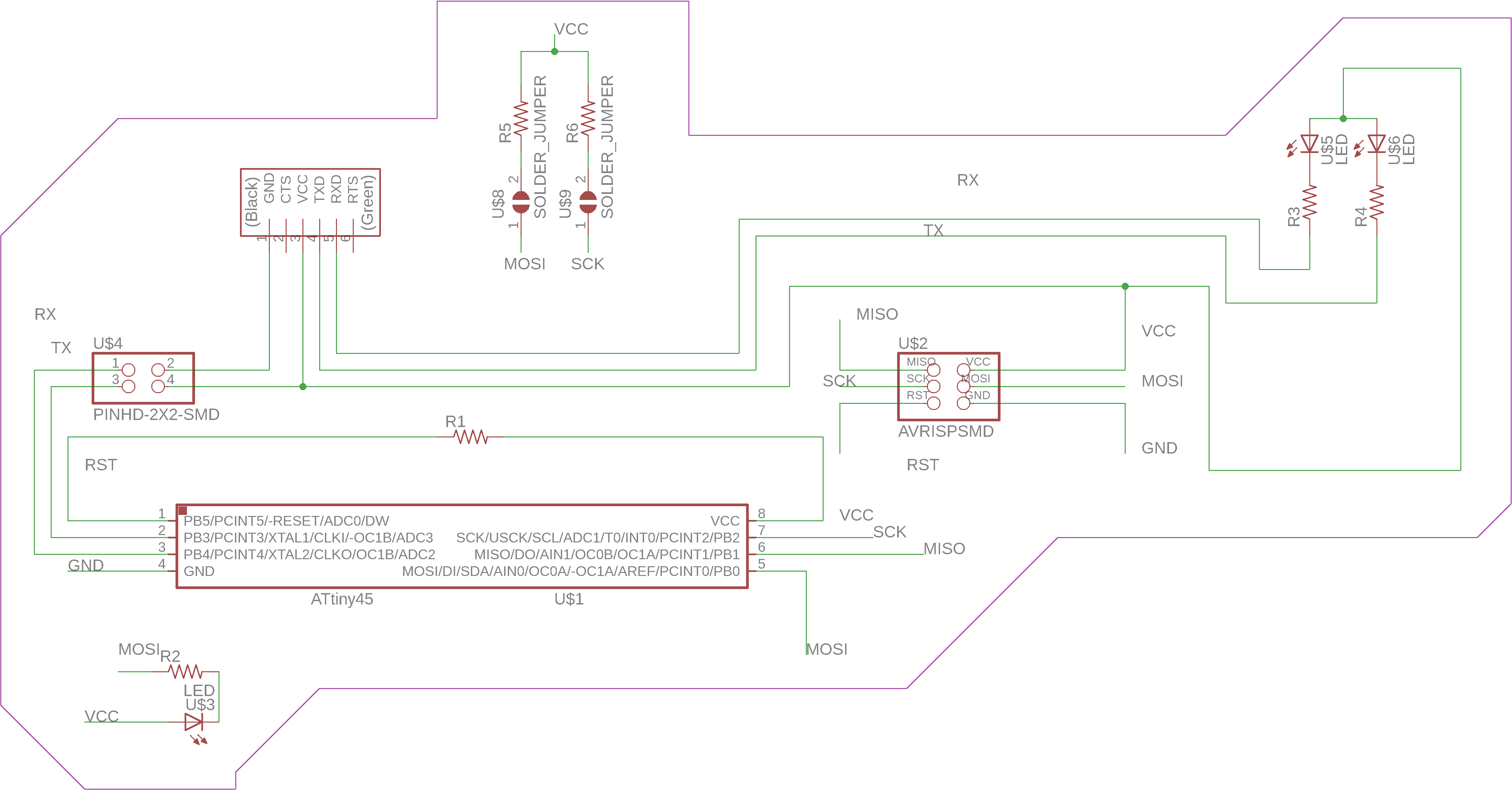
Schematic
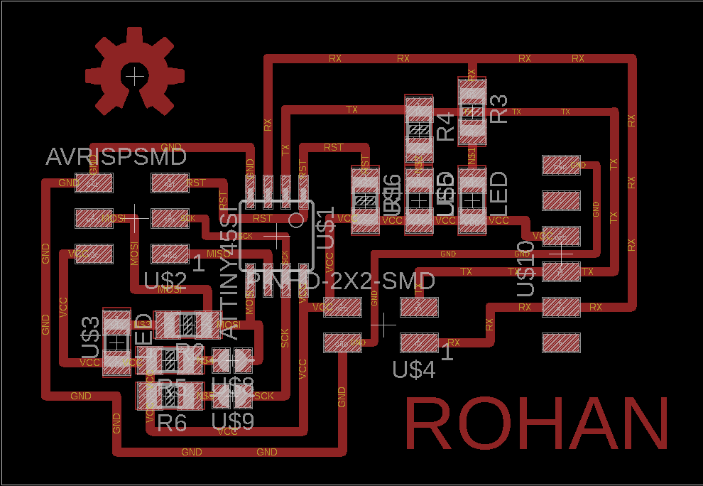
Board
The Schematic, Board, Traces and outline files are available here
As you can see, my board is very much similar to Neil's board.
I've added two LEDs on the RX and TX lines because I like it when they blink while transferring data.
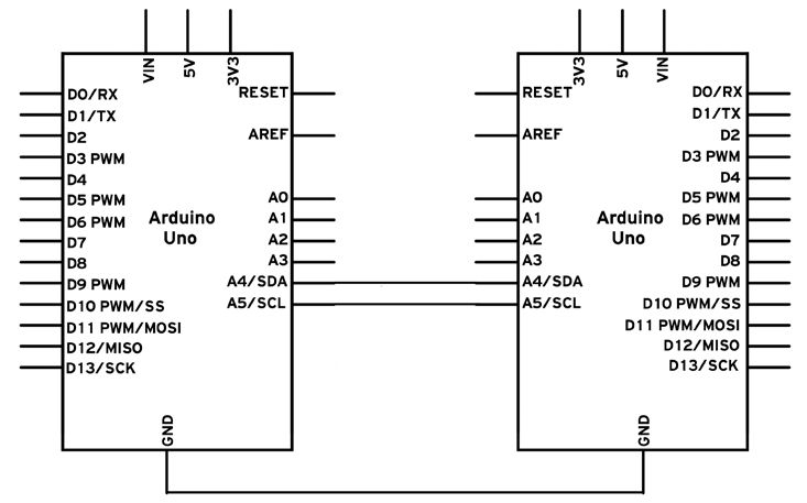
I also created a simple Arduino based I2C circuit, just to see how everything works
I2C pronounced as 'I squared C' is another data transfer serial bus, developed and invented by Phillips.
I2C uses pins similar to AVR ISCP headers so no new headers are required.
I2C is synchronous hence there needs to be a common clock signal, it is provided by master.
The two pins necessary for I2C are SDA (Serial Data) and SCL (Serial Clock). SDA is the same pin as MOSI.
Here I have used only the Vcc and Gnd from FTDI cable to power the board.
Just for fun, I also flashed the helloworld board with I2C program and connected it.
The code used above was Neils' code, which is very nice but I wanted them to work on my own code hence I decided to write I2C communication program using Wire.h library.
For initial part, I decided to write the code for Arduino UNO.
The code for master is given by:
void loop() {
Wire.beginTransmission(8); // transmit to device #8
Wire.write("x received is "); // sends five bytes
Wire.write(x); // sends one byte
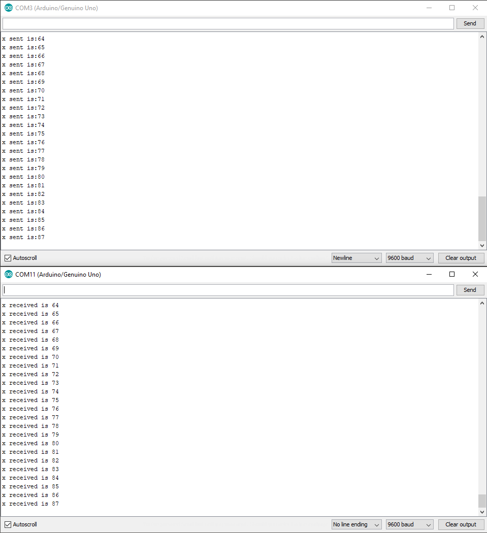
Serial.print("x sent is:");
Serial.println(x);
Wire.endTransmission(); // stop transmitting
x++;
delay(500);
}
Understanding the code,
First, let's look at the master. We need to include the required Wire.h library
Then, in the setup function, we begin the I2C bus using the Wire.begin() function. If no argument is provided in the function, Arduino will start as a master.
We use the following functions to begin a transmission to the device with the address 8 Wire.beginTransmission(device no);
Then write the character Wire.write(data to be sent);,
and then we stop the transmission Wire.endTransmission();
Here additionally I have used the the serial command because I need some visual proof on both sides that data is being sent and received
While the code for slave is given by
        #include <Wire.h>


void setup() {

  Wire.begin(8);              // join i2c bus with address #8

  Wire.onReceive(receiveEvent); // register event

  Serial.begin(9600);           // start serial for output

}


void loop() {

  delay(100);

}


void receiveEvent(int howMany) {

  while (1 < Wire.available()) { // loop through all but the last

    char c = Wire.read(); // receive byte as a character

    Serial.print(c);         // print the character

  }

  int x = Wire.read();    // receive byte as an integer

  Serial.println(x);         // print the integer

}
Understanding the code,
We also include the Wire.h library here by using Wire.being(device no);
but now I have used the I2C bus using Wire.begin(8) The number in the argument is the address we want to use for the Arduino.
All devices with address 8 will receive the transmission.
Now to see that the boards are actually communicating the slave must react somehow when it receives an I2C transmission.
I have considered the incoming event as a event
For this in setup I have used Wire.onReceive(receiveEvent);
Now I have defined a function which executes every time there is an event
This function will now collected all that in received in the transmission the character variable 'c'
This is then outputted via serial
The video of working is as seen below
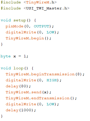
I2C in ATtiny 45
I have implemented the same code in my boards here but with a twist
For the tiny series, to implement I2C I found out that Wire.h (used above) is not used.
The ATtiny45 microprocessor is an 8 pin chip with 6 (max!) I/O ports. Using an I2C bus greatly expands the possibilities of what you can do with this chip.
The ATtiny45 (and it's cousins) does not have I2C (or SPI) "built in".
Instead it has a Universal Serial Interface (USI) that can be used to facilitate I2C and SPI.
Tiny wire is also divided into two parts
TinyWire -S
The library with only slaves related files.
TinyWire -M
The library with only master related files.
Details can be found on the github page of lucullusTheOnly who developed these libraries available here.
The TinyWire -M:
Download the library from here
Understanding the basics of TinyWire M
SAGE is modeled after the standard Wire library . . .
Even after for a few days, I could not get L2C to work as required.
Hence I shifted to Async
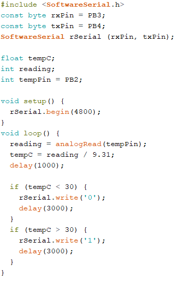
I had already made a lm35 board before.
I decided to make a network such that there will be two boards.
One with sensor and one with LED output.
If the temperature goes beyond a certain range, the LED will lightup.
I wrote the code for the sensor board as below, my friend Chaitanya helped me to write the code.
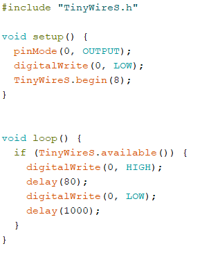
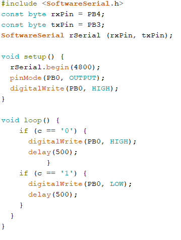
And the code for the LED board is as below
It is noted that my LED as active LOW, hence turning them LOW in program actually turns them ON
The video is linked below