b. Programming: i. DSO ii. Serial Plotter/Monitor (Arduino) iii. Python Script
3. Group Assignment: Measure analog Levels and digital signal. (using DSO- Write about you understanding)
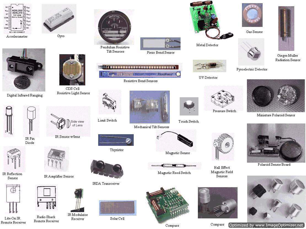
1. Introduction about Input Devices
Input Devices: Electronics device which can get analog signal from out side and send to the controller and process it in digital signal (serial monitor in hexadecimal value) it know as input devices. Basically such kind of devices are get data from environment status and doing work as controller programmed language. This types of input devices are know as sensors.
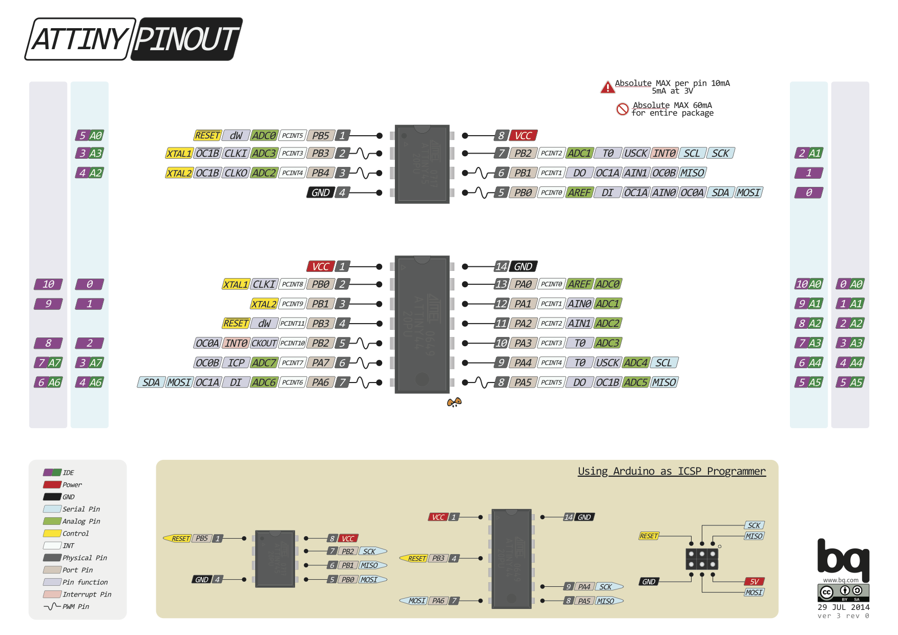
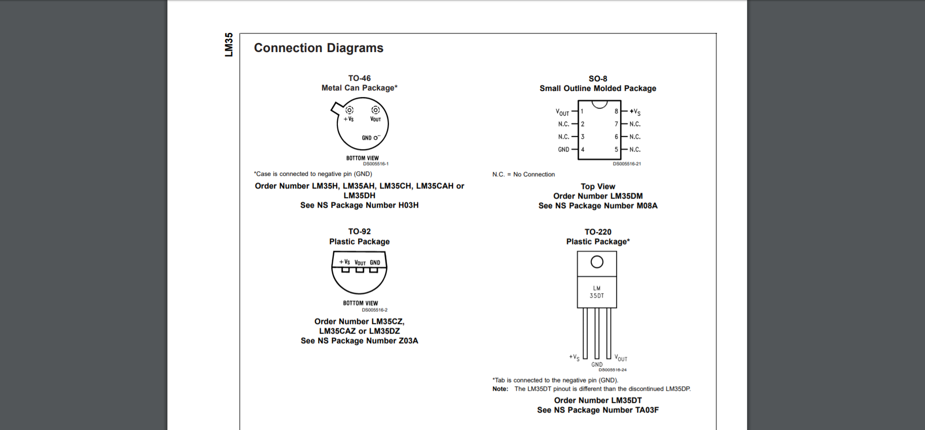
Controller: (ATtiny44) For this week I'm using ATtiny44 micro-controller for controlling the sensor, For my final project i will use Temperature sensor (LM35DZ) for detecting the temperature and after get this data out output device will be stops. Before going to schematic design first I read Datasheet about ATtiny44 and figure out how I design my schematic
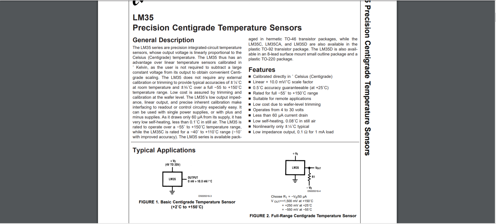
Sensors (LM35DZ) For this week i used temperature sensor, model LM35DZ. this is the give most accurate data from the other sensors have. First i read the data sheet and take some clear info about the LM35DZ.
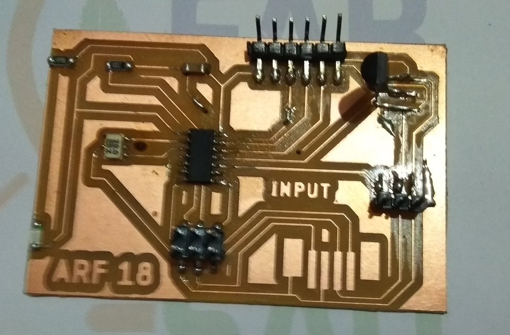
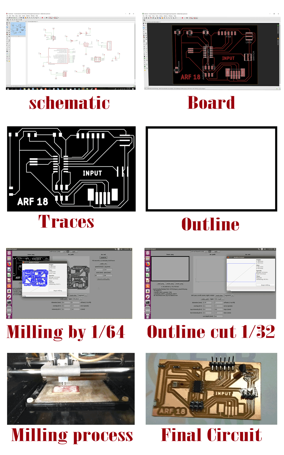
Input Board PCB making: For PCB making i follow the process which i was learned from the electronic design assignment. Here also i give combine images below:
Input Board PCB Design and Soldering
1. Schematic: After reading and Datasheet and talked with my instructor, I designed board schematic with follow the library.
2. Board: Now I switch to the board design and first i going to auto-routing then I maintain the ERC for good design
3. Traces and outline: Then i export the file as monochrome in 1000 resolution for milling and make as outline for board final cut.
4. Milling: Then i follow the milling rule like mill the traces line then used 1/64 end mill of Modella 20MDX and the cut the out line i used 1/32 end mill.
5. Milling process: During milling process care about the gravity of the end mill and offset and intensity etc.
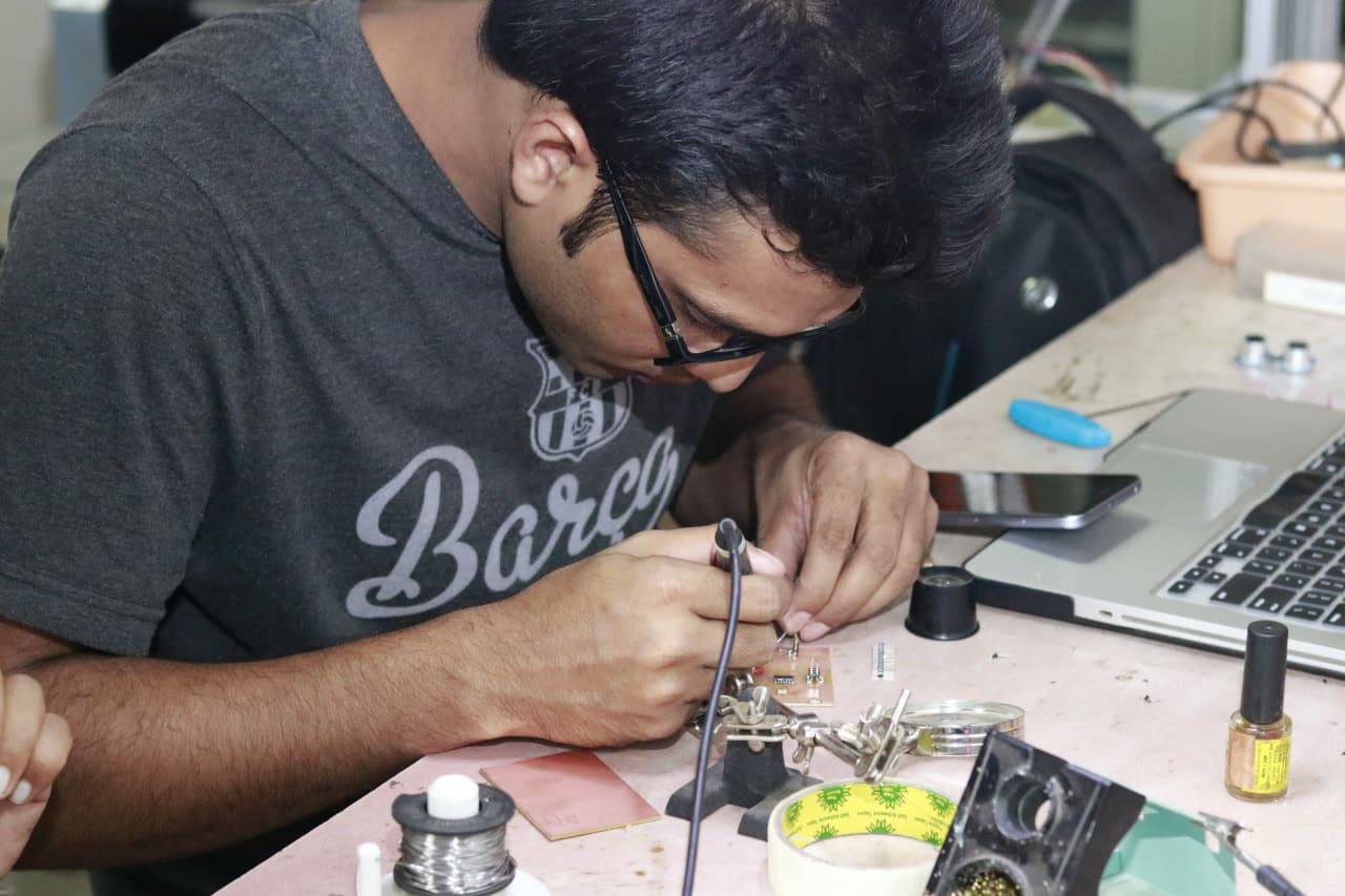
5. Final Board: Then i get the final board (here i add the soldering board.
I working on the soldering process of the board.
Programming of micro-controller: Arduino
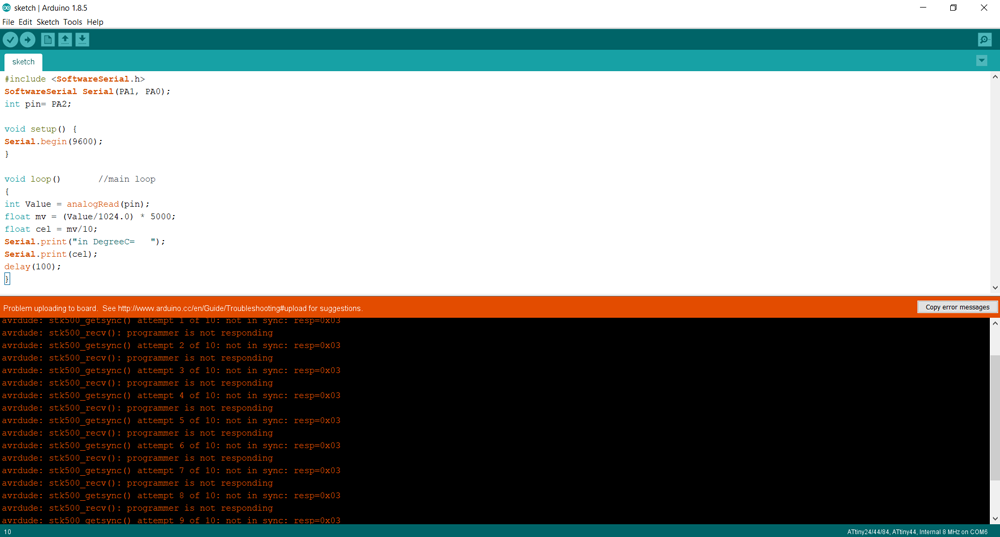
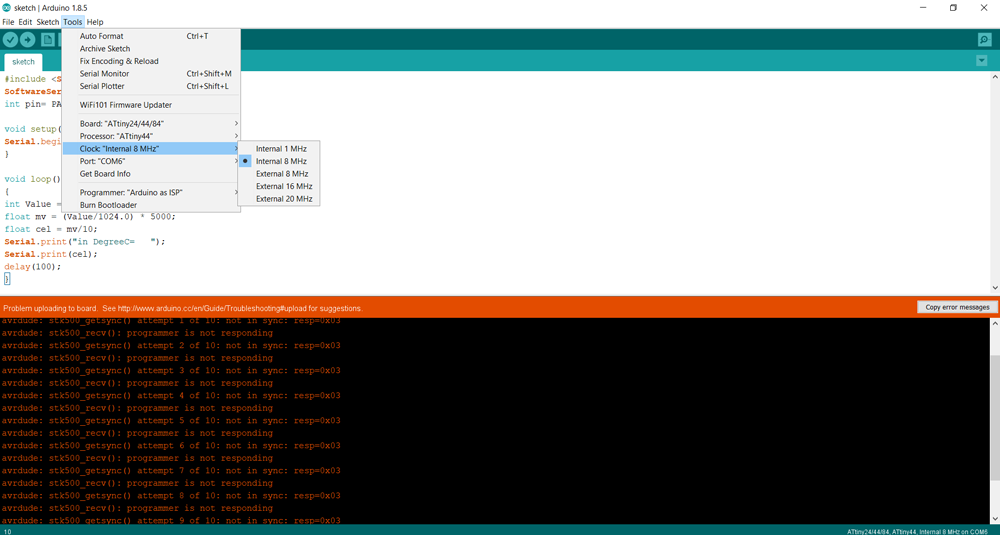
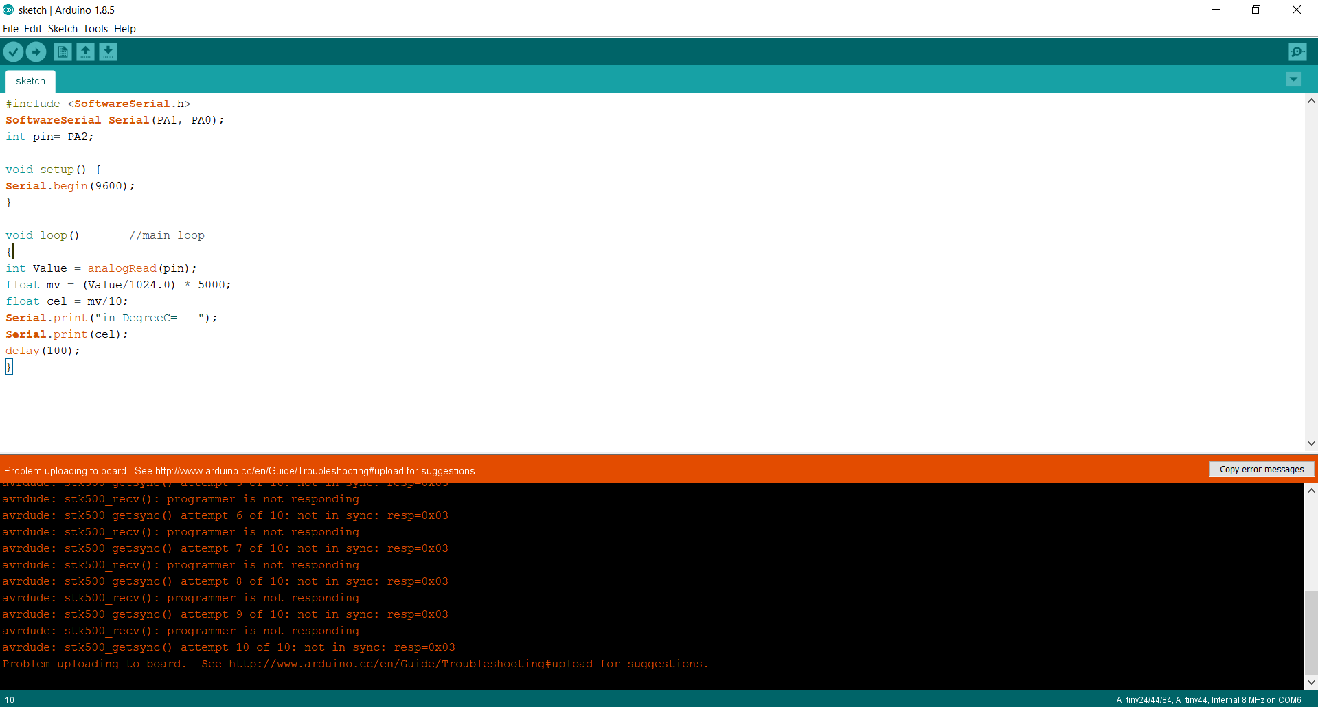
Arduino: First I tried to program the board by the Arduino IDE with arduino sketch. I'm using FabISP for programming but unfortunately my fabisp is not working (it show rc=-1) error. Then i used arduino as ISP, where try to program the board. First i tried arduino with 8Mhz internal and second 20 external but every time it show programmers error.
AVR ISP: Second i used AVR ISP for programming te board, here i faces some problem, first it not programmed, why i don't know. I show same problem as Arduino
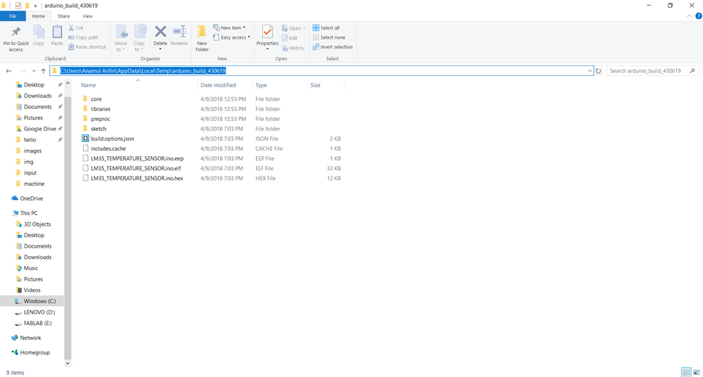
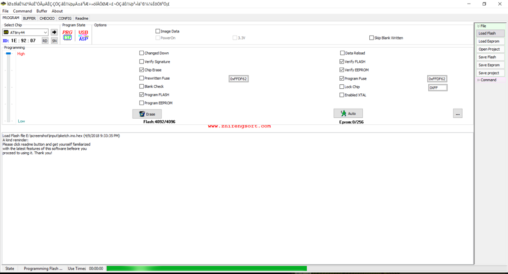
ProgISP Software: I was also tried to programmed the board by using progISP software by using AVR-ISP programmer. Thats time i collect the hex file for Arduino temp file as hex format then i programmed it, here the board get upload the data but when i open Arduino serial monitor, here it don't show any data.
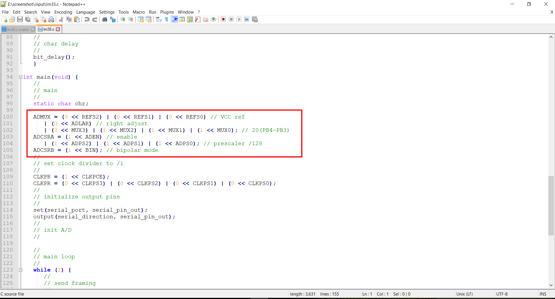
Programming of micro-controller: C Code
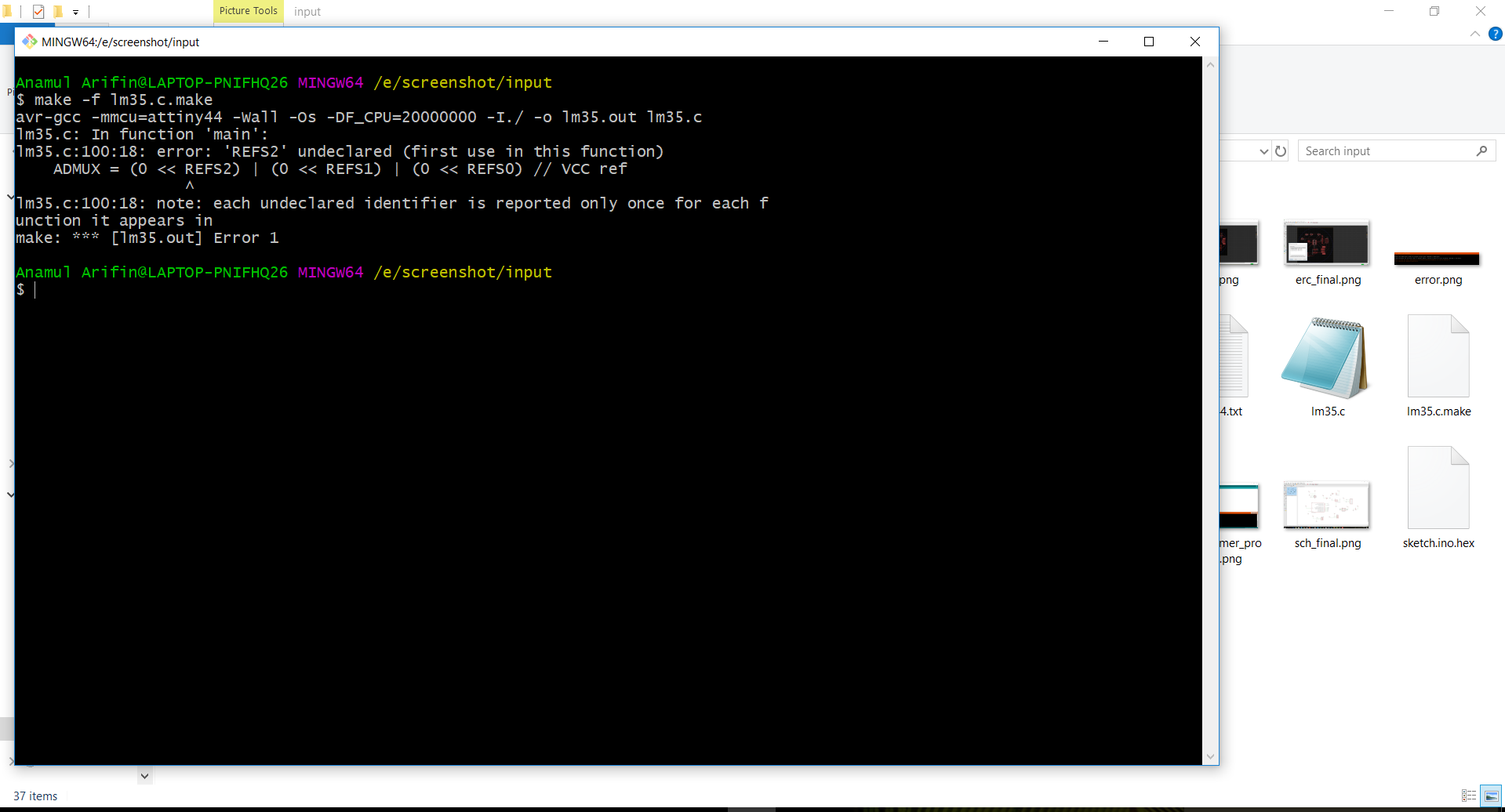
First I have little bit knowledge about c code, as download the c file from the neil code and edit the pin position as by schematic design, but here also show error when i going the program on it. after that i didn't try.
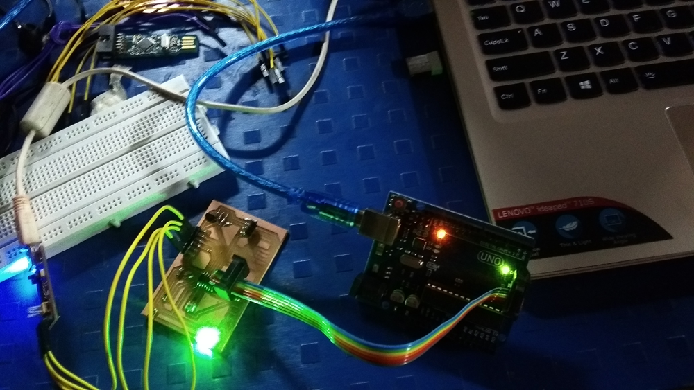
I'm again repeat Arduino Uno board as a programmer.
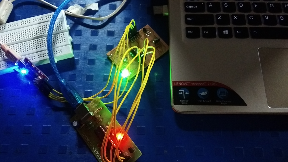
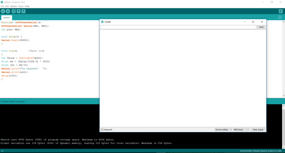
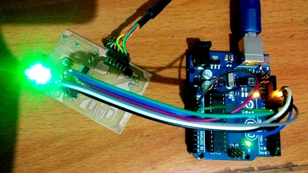
After failure three different process I follow the as procedure for making boot loader of an Arduino board then upload the sketch, then board is connectd with FTDI cable to show the data in serial monitor of Arduino, finally it works.
In Video show the sensor data in the serial monitor of the Arduino IDE.
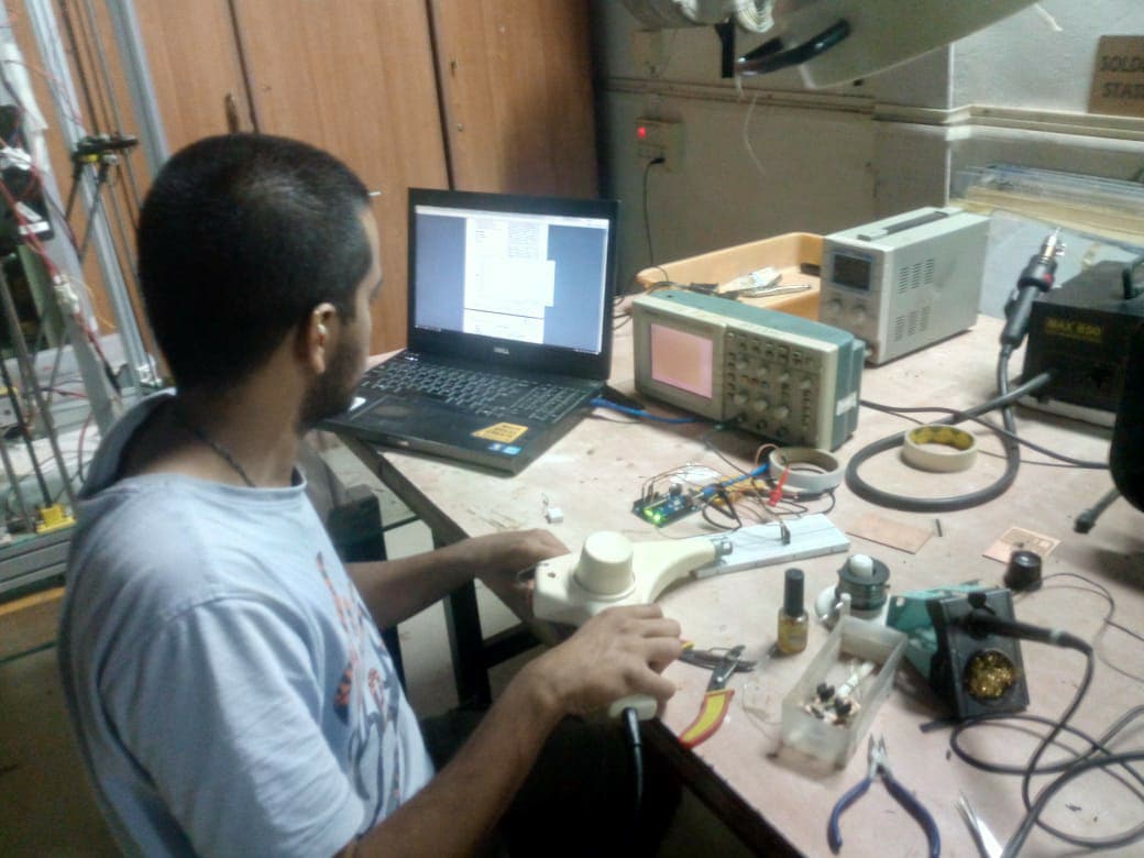
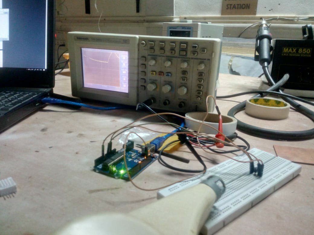
Group Works
For group assignment we check the temperature sensor reading with serial monitor and electrical signal on DSO. Rohan Rege he was doing the job.