
Output Devices
- 1. Add an output device to a micro-controller board you've designed
- 2. Program it to do something ( Arduino /C code)
Output Devices
Output Devices: According to Wikipedia, Some types of output are text, graphics, tactile, audio, and video. Text consists of characters that are used to create words, sentences, and paragraphs. Graphics are digital representations of non text information such as drawings, charts, photographs, and animation . Tactile output such as raised line drawings may be useful for some individuals who are blind. Audio is music, speech, or any other sound. Video consists of images played back at speeds to provide the appearance of full motion.
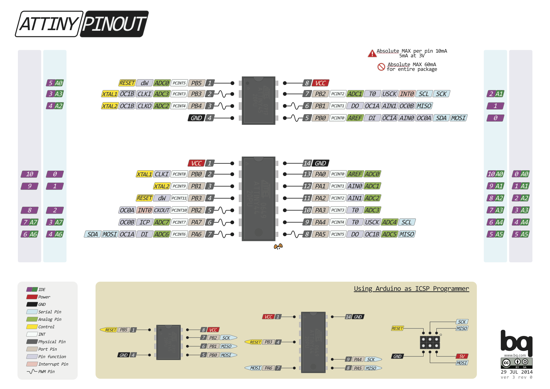
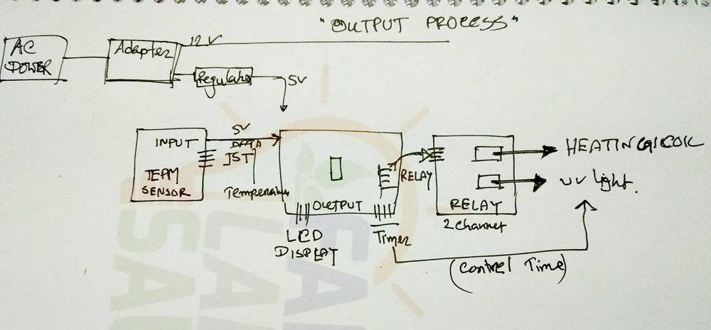
Controller: (ATtiny44) For this week I'm using Attiny44 micro-controller for controlling the sensor, For my final project i will use temperature sensor (LM35DZ) for detecting the temperature and after get this data out output device will drive the heating element and it analog data will be high and low according to the input device (sensors) which give. Before going to schematic design first I read datasheet about Attiny44 and figure out how i design my schematic
Output Board PCB making: For PCB making i follow the process which i was learned from the electronic design assignment. Check in the below about output and relay board images and description about how i was made this.
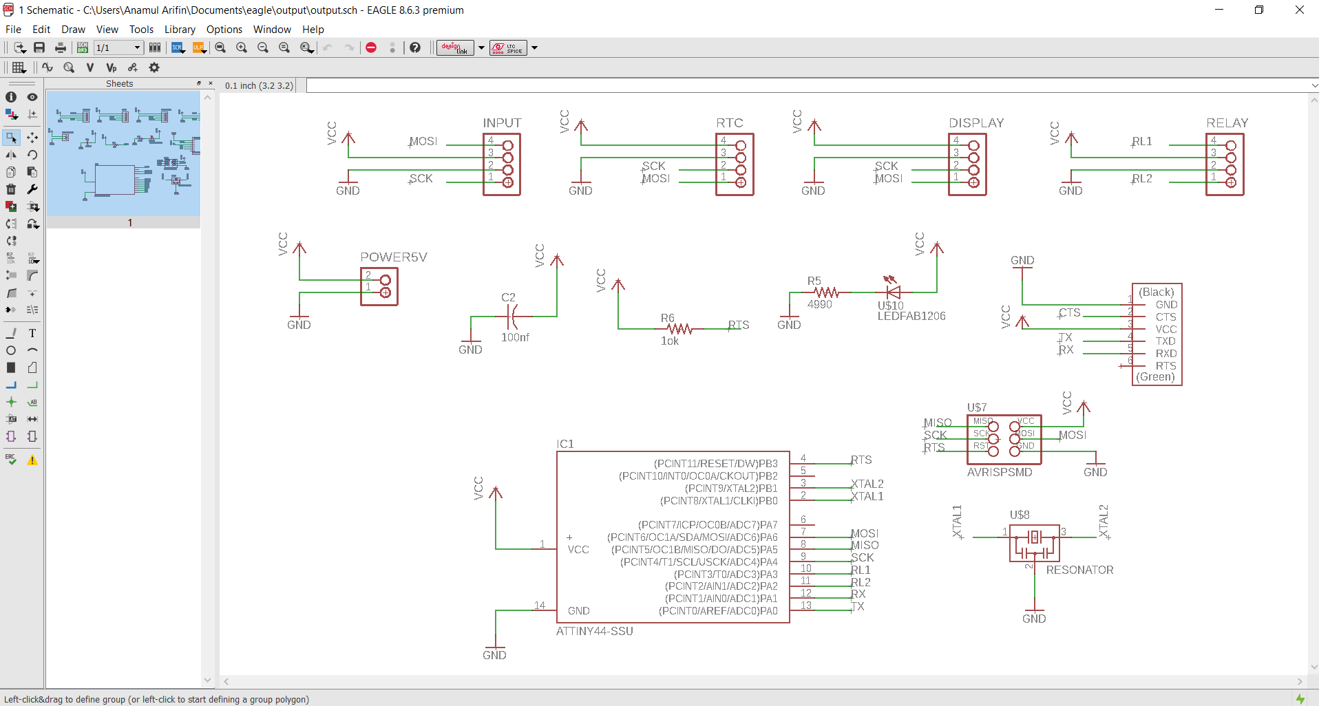
1. Schematic: After reading and datasheet and talked with my instructor, I designed board schematic with follow th library.
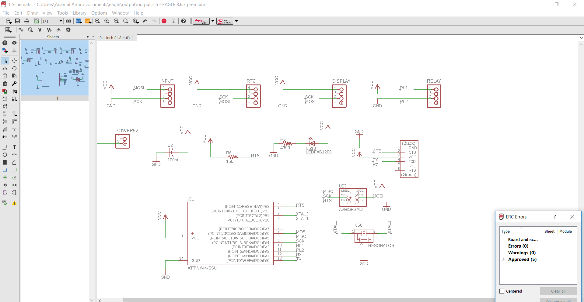
2. After completing the schematic design I checked the ERC in my design, here show some error for non attached pin of component.
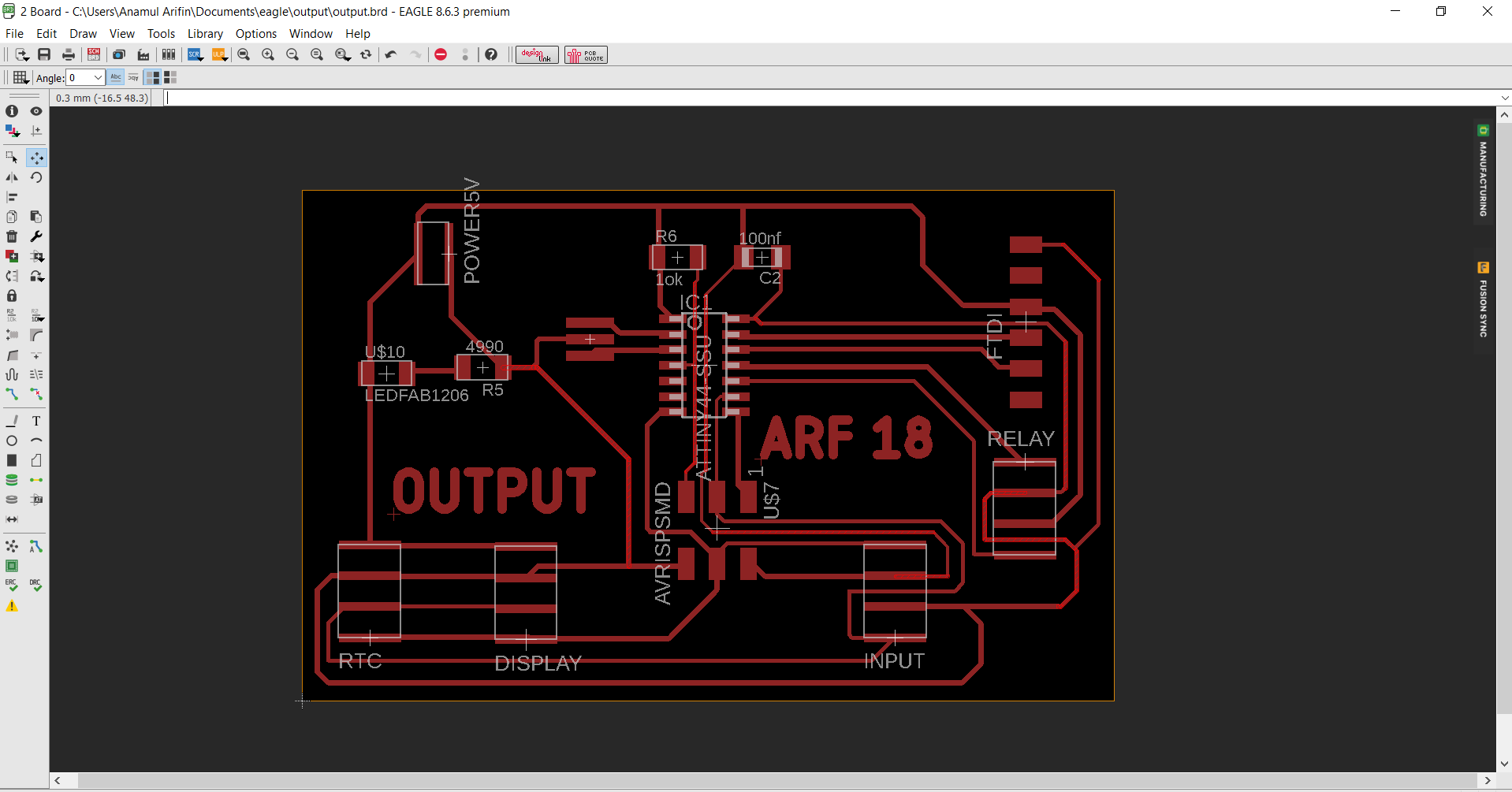
3. Board: Now I switch to the board design and first i going to auto-routing for checking the route then in edit it again for increasing the width and replace the area also, with maintained the ERC for good design
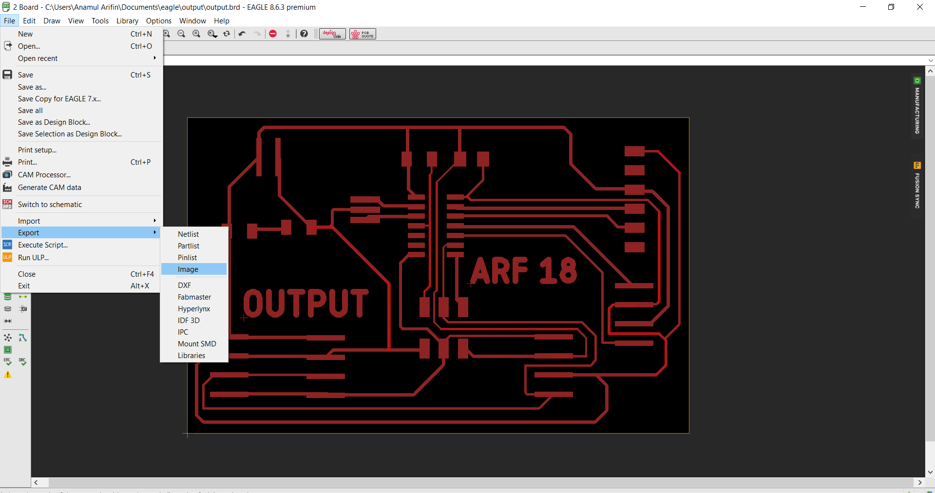
4. Export the file in monochrome format in 1000 resolution, and send it to the GIMP for further editing.
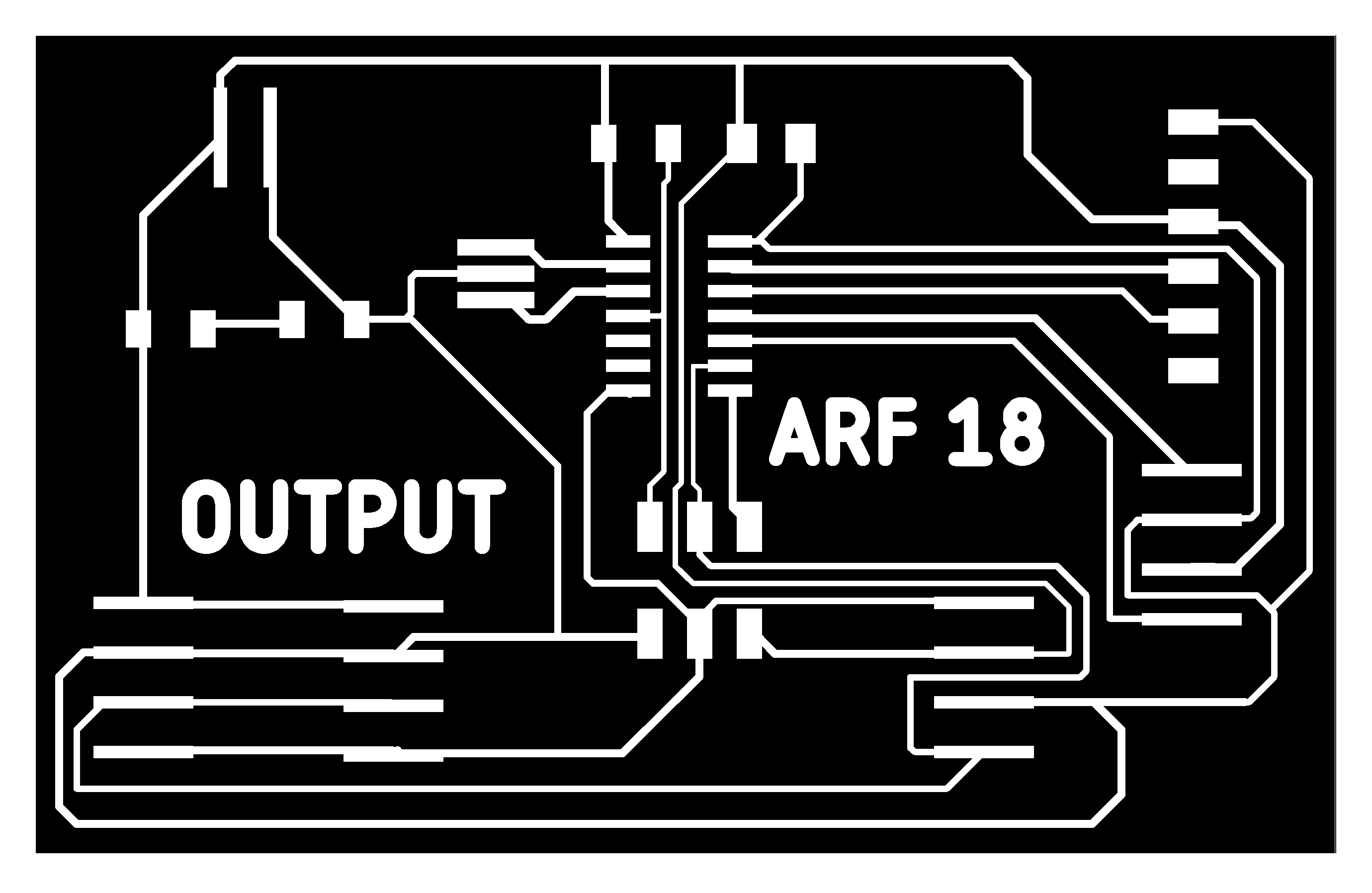
5. I made the proper board traces file for milling

6.This is the cuting outline for the board with 1/32 end mill
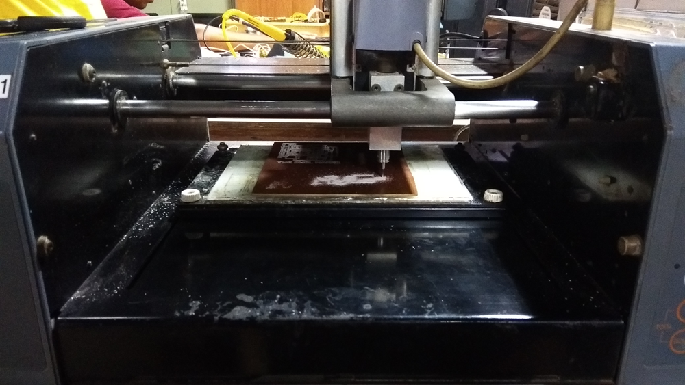
7.Now i start my milling with properly attached the PCB along the machine working body.
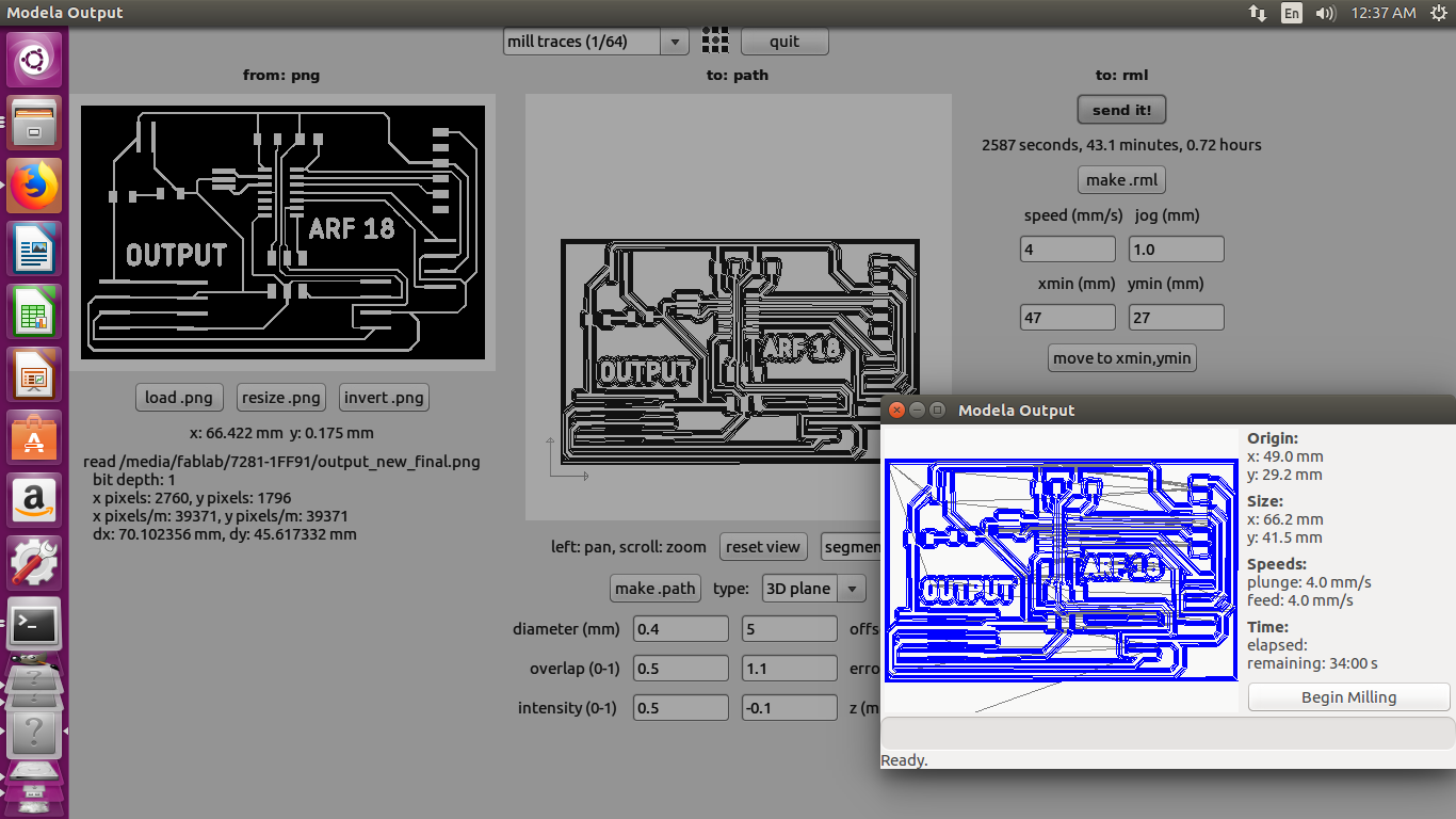
8. Milling process going on by 1/64 end mill for milling the traces on the board.
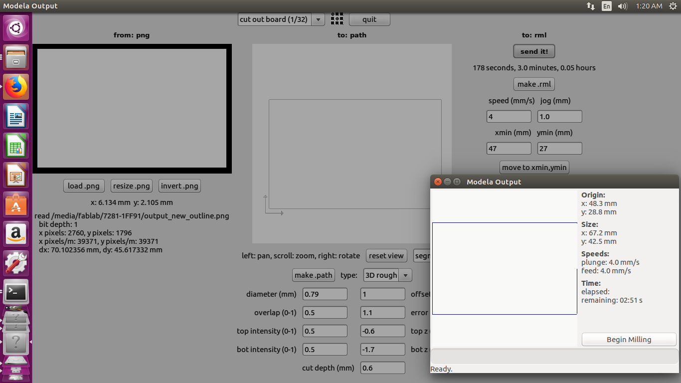
9.After milling for cutting the outline of circuit board.
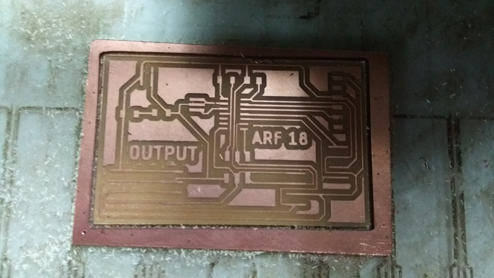
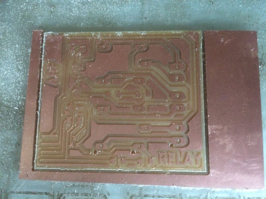
10.Board after milling and outline cutting
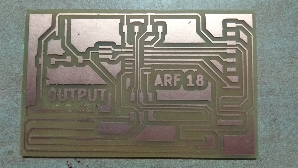
11. Final board and ready for soldering
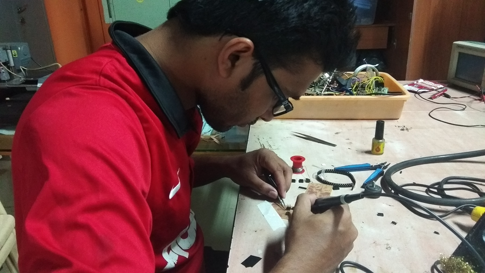
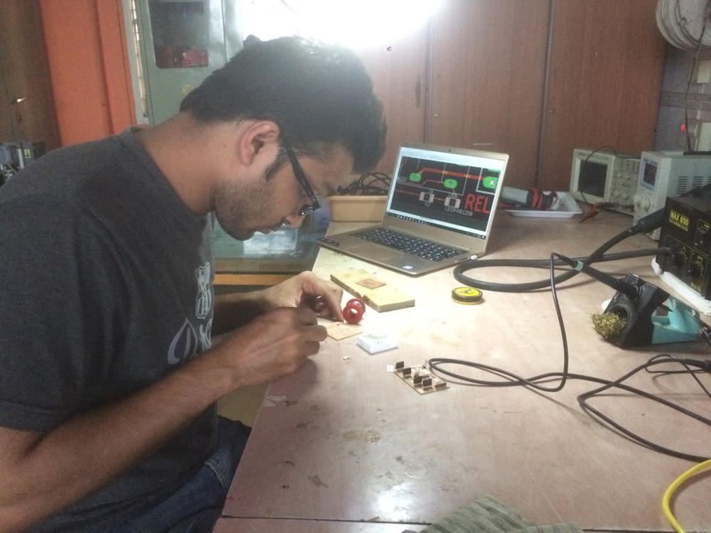
12. Start to soldering the design component according to the schematic design
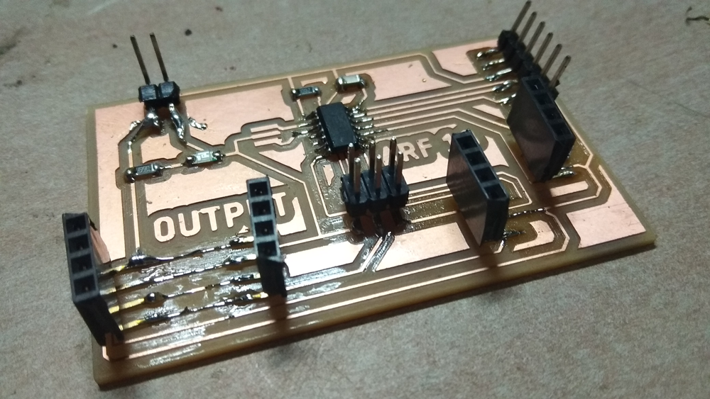
13. Board after soldering
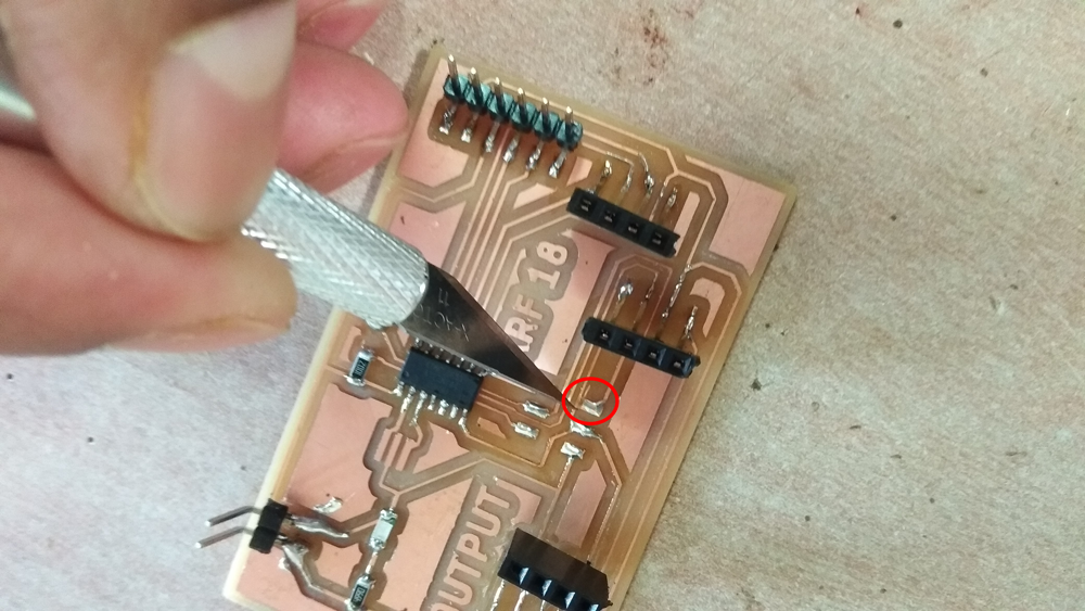
14. After soldering I faced one error in my board that is the VCC pad are attached with MOSI traces line, then I used hot air gun for remove the ISP pin header and used exacto knife for making a gap between the pad and trace.
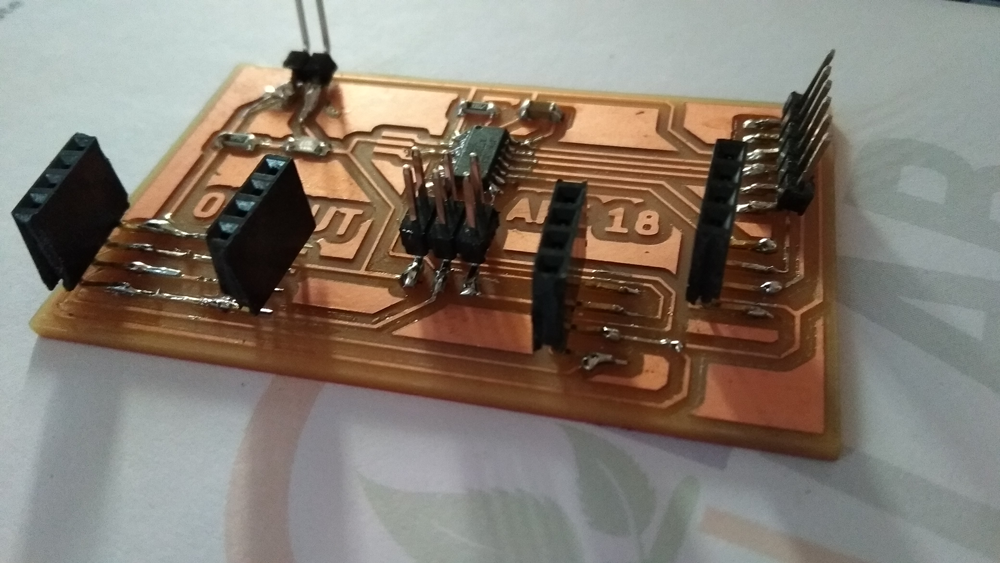
15.Now this is my output board
Description about OUTPUT board: When i was design this board, I had a plan to use of this board like LM35 temperature sensor data come from input board to output board via I2C protocol, second i want to use RTC by I2C and OLED also want to use I2C protocol. then singal pass through vai one port to Relays board. For serial communication I also keep FTDI pin. In this board all programme are control by ATtiny44A.
Before going to design relay board I read about relay and how its works for some web source.
A relay is an electromagnetic switch operated by a relatively small electric current that can turn on or off a much larger electric current. The heart of a relay is an electromagnet (a coil of wire that becomes a temporary magnet when electricity flows through it). You can think of a relay as a kind of electric lever: switch it on with a tiny current and it switches on ("leverages") another appliance using a much bigger current. Why is that useful? As the name suggests, many sensors are incredibly sensitive pieces of electronic equipment and produce only small electric currents. But often we need them to drive bigger pieces of apparatus that use bigger currents. Relays bridge the gap, making it possible for small currents to activate larger ones. That means relays can work either as switches (turning things on and off) or as amplifiers (converting small currents into larger ones).
Here are two simple animations illustrating how relays use one circuit to switch on a second circuit.
When power flows through the first circuit
This is an example of a "normally open" (NO) relay: the contacts in the second circuit are not connected by default, and switch on only when a current flows through the magnet. Other relays are "normally closed" (NC; the contacts are connected so a current flows through them by default) and switch off only when the magnet is activated, pulling or pushing the contacts apart. Normally open relays are the most common.
Here's another animation showing how a relay links two circuits together. It's essentially the same thing drawn in a slightly different way. On the left side, there's an input circuit powered by a switch or a sensor of some kind. When this circuit is activated, it feeds current to an electromagnet that pulls a metal switch closed and activates the second, output circuit (on the right side). The relatively small current in the input circuit thus activates the larger current in the output circuit:
Requirements to drive relay: In my project I'm going to use one 50W/12V heating coil which is need 4.15A more or less load needed. For this much load I going to use 5V DC and 7A load capacity relay in my relay board.
Relay Board Design and Soldering
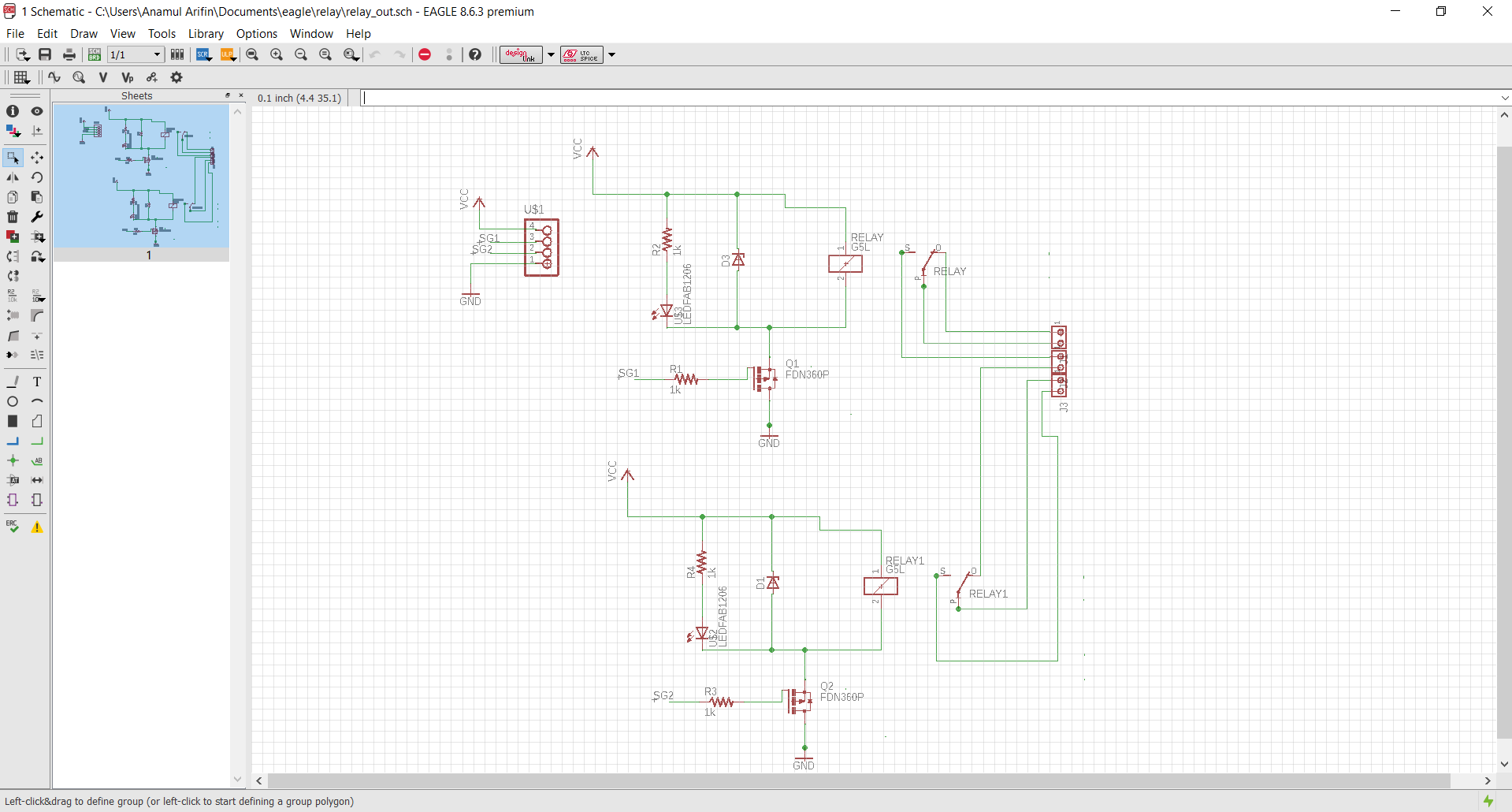
1. Schematic: After reading and datasheet and talked with my instructor, I designed board schematic with follow th library.This is the 2-channel relay module
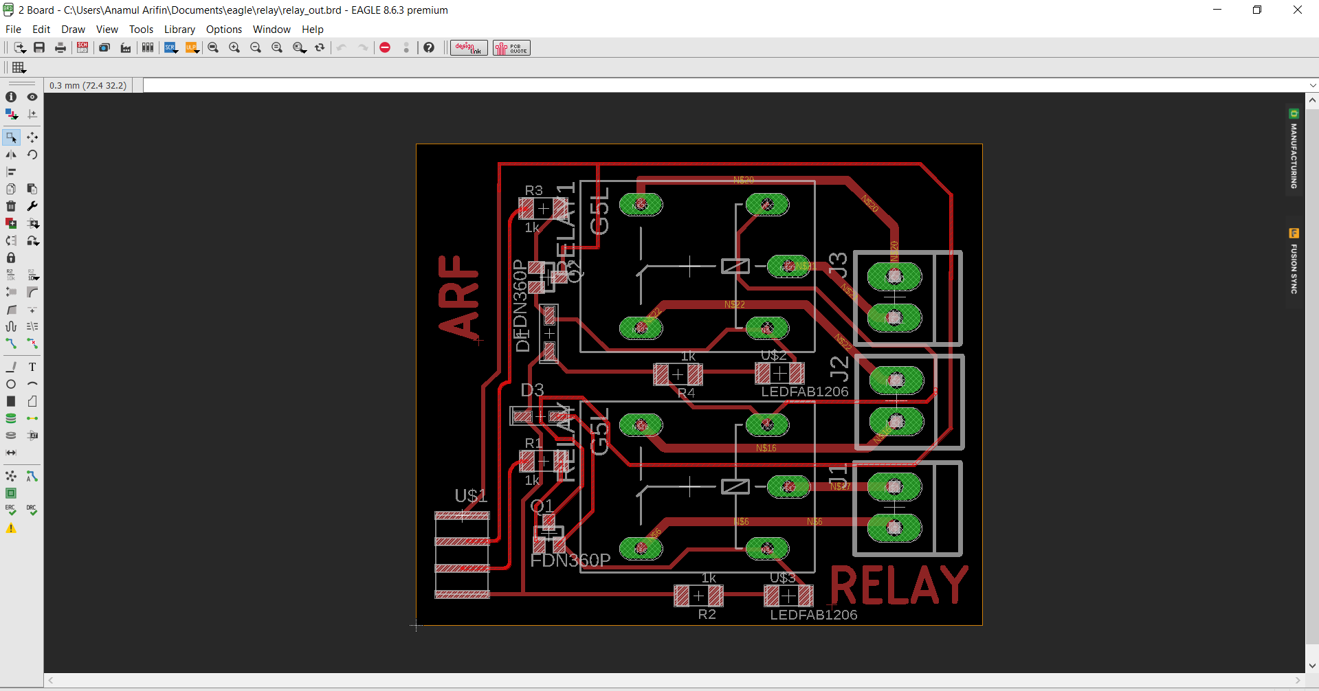
2. Board: Now I switch to the board design and first i going to auto-routing for checking the route then in edit it again for increasing the width and replace the area also, with maintained the ERC for good design
3. Export the file in monochrome format in 1000 resolution, and send it to the GIMP for further editing.

4. I made the proper board traces file for milling

5.Making the pad for drilling
6.Now i start my milling with properly attached the PCB along the machine working body.
7. Milling process going on by 1/64 end mill for milling the traces on the board.
8.After milling for cutting the outline of circuit board.
9.Board after milling and outline cutting
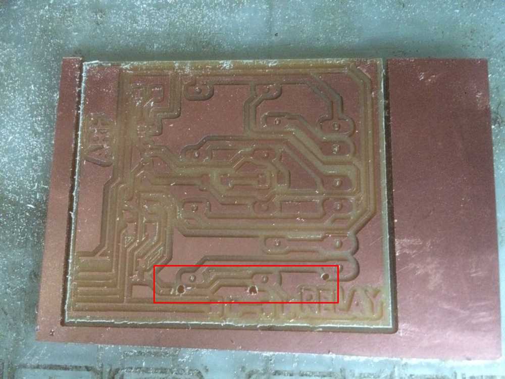
10. During the drilling the pad hole, there is one mistake which is the pad position is not proper place thats why it was drill wrong place and one traces are wipe out
11. Then i going to soldering and here i used one 0 ohm resistor in the wiped trace.
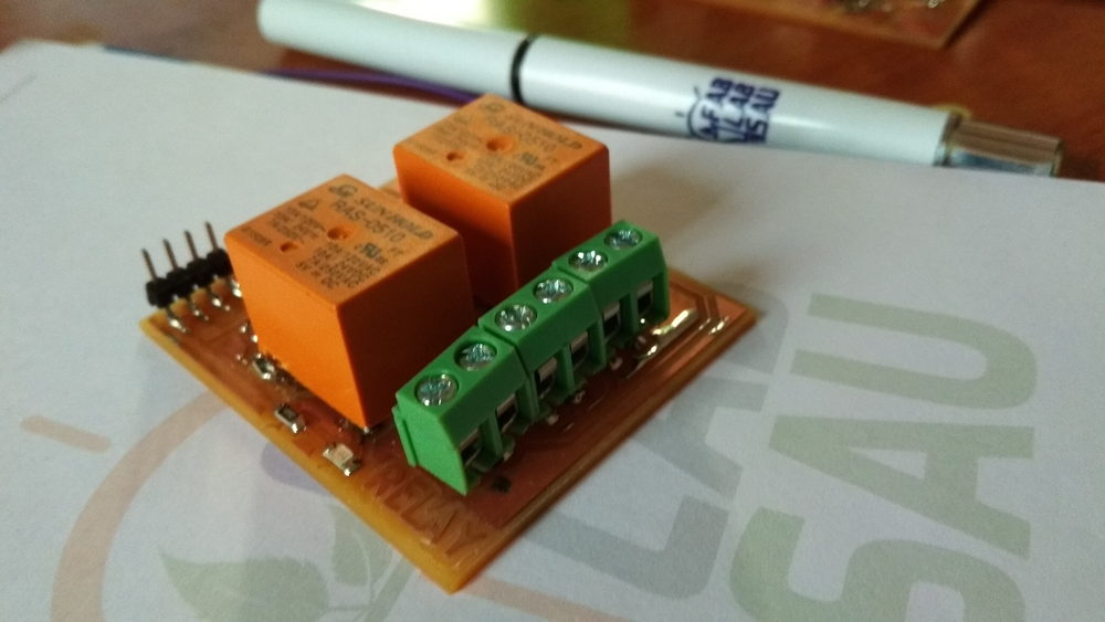
12. This is my final relay module for my output device.
In this output board i design to sending data from microcontroller to source vai I2C communication protocol. Here I denoted PIN PA4 for SCK, and PA6 for MOSI. Output board to relay signal pass through vai pin PA2 for relay1 signal, PA3 for relay2 signal.
Arduino: First I tried to program the board by the Arduino IDE with arduino sketch. I'm using FabISP for programming but unfortunately my fabisp is not working (it show rc=-1) error. Then i used arduino as ISP, where try to program the board. First i tried arduino as 8mhz internal as Android ISP, First i burn the Arduino Uno as bootloader by selecting proper tools setup
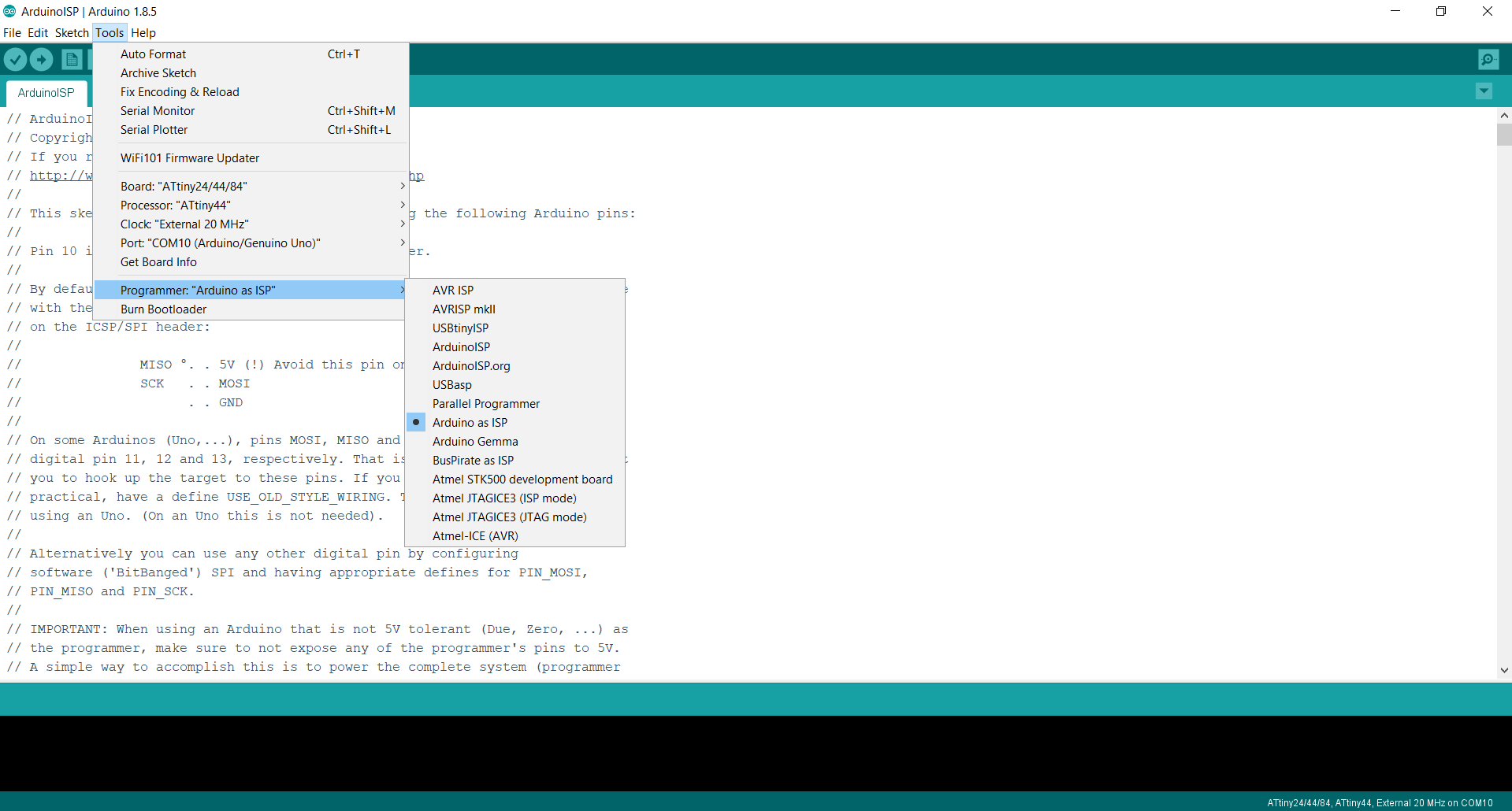
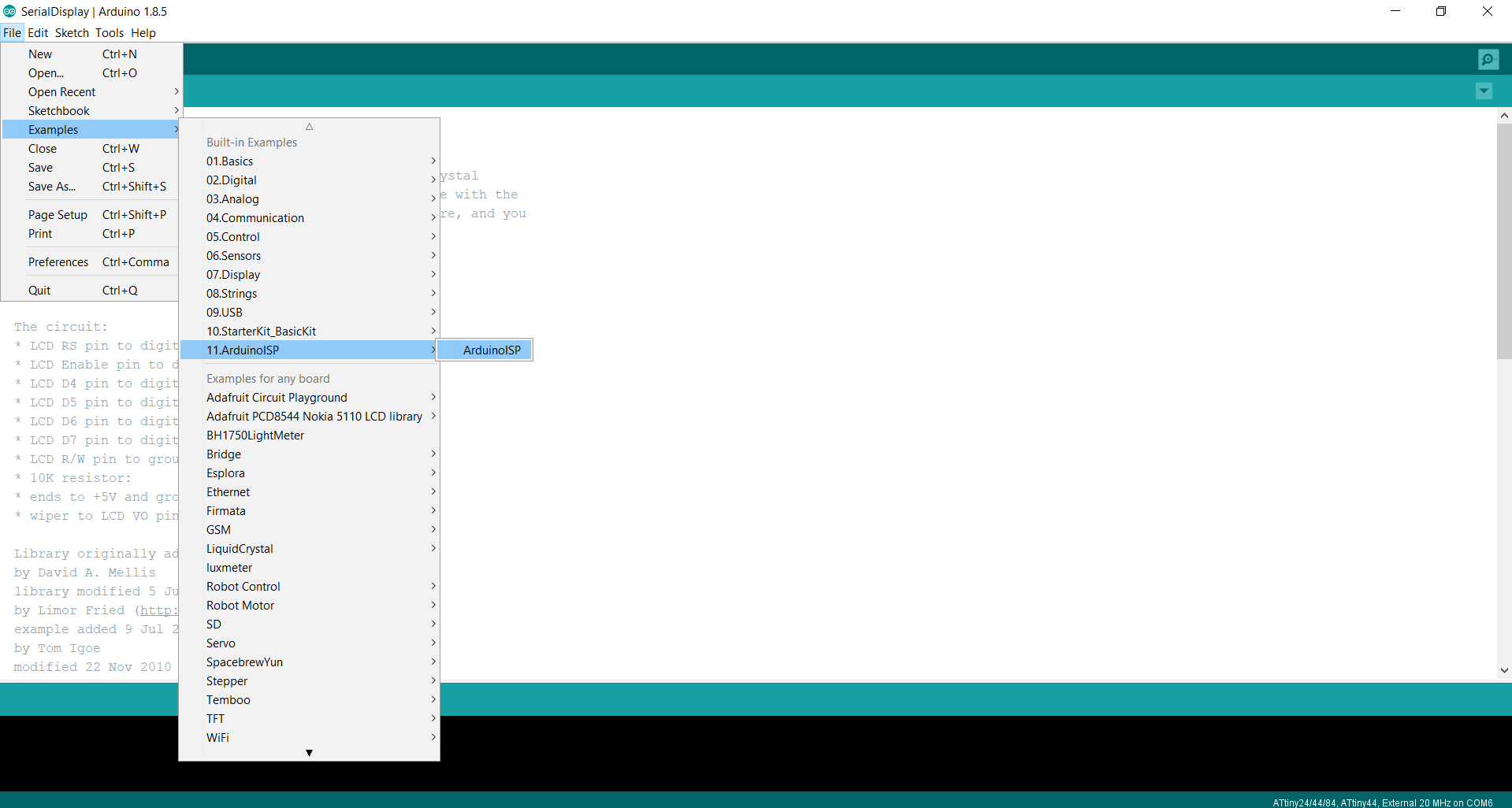
1. First i made a programmable ISP of an Arduino UNO board according to the tools setup. Then I go and select the file-example-11.Arduino ISP
2.In tools here i check the port, clock at 8Mhz(here I'm using internal clock speed, i didn't use resonator for checking), Processor Attiny44 and board Attiny44
3.Then burn the bootloader for making ISP
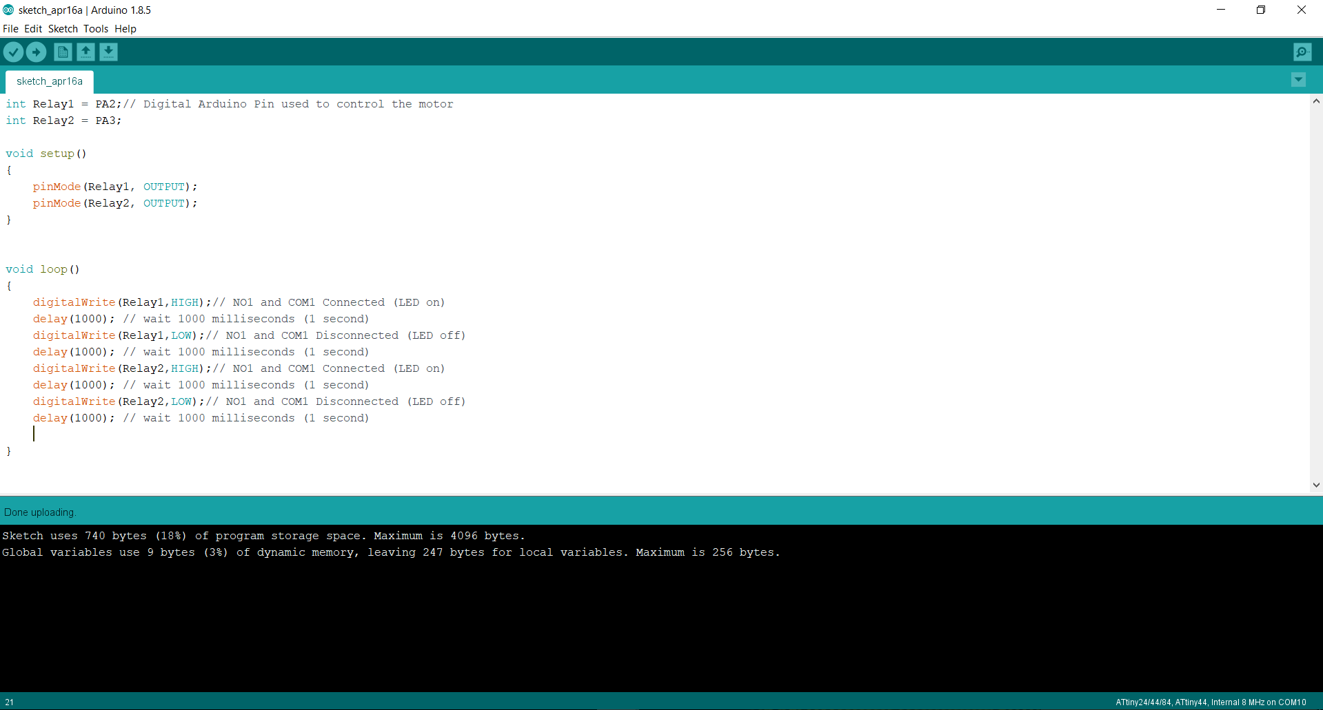
4.Now I'm programming the board for testing the relay is working or not, Now i have no output device (but i ordered in on-line), Is there is nothing to show proper inventory. Here we delivered the pin no and the signal value High and Low.
5. Connection of output board and relay board with Arduino for programming
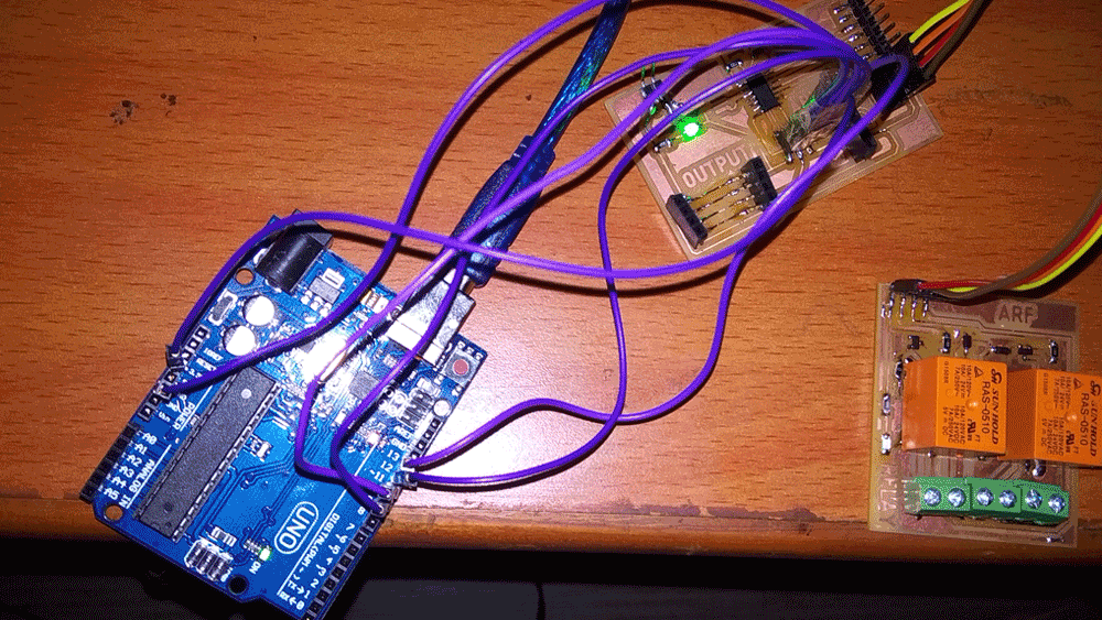
6. Output board now is programmed, view in following video
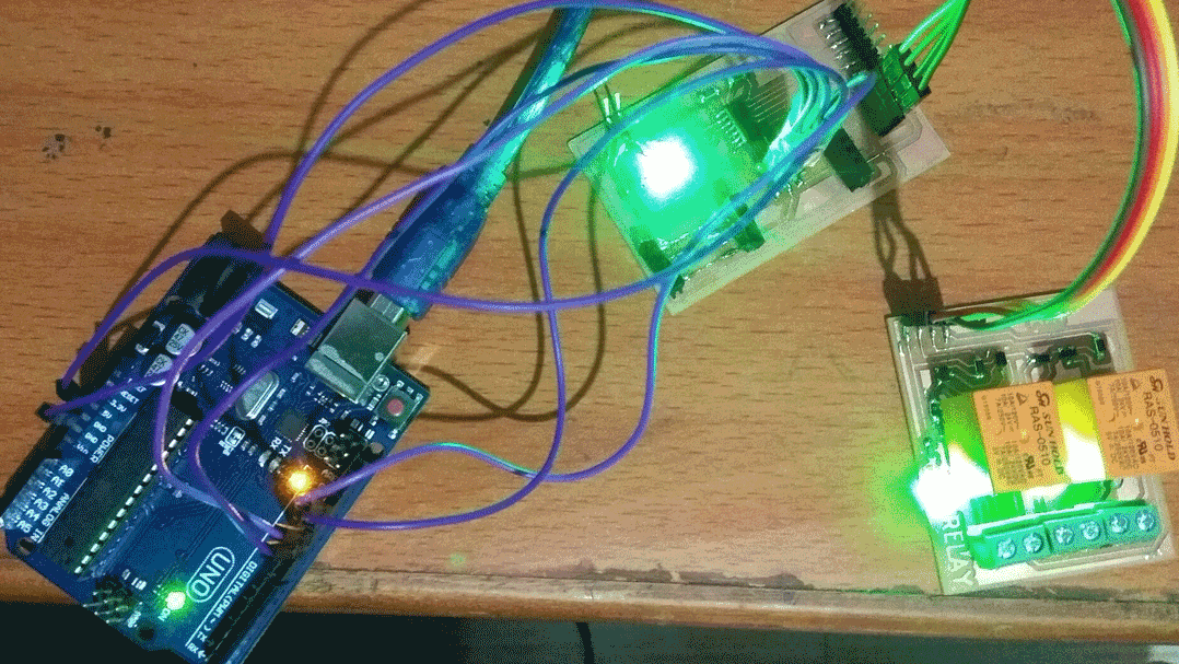
7. Video for the LED blinking by high and low command.