
Interface and Application Programming
- 1. Write an application that interfaces with an input &/or output device that you made
- 2. Compare as many tool options as possible
Interface and Application Programming
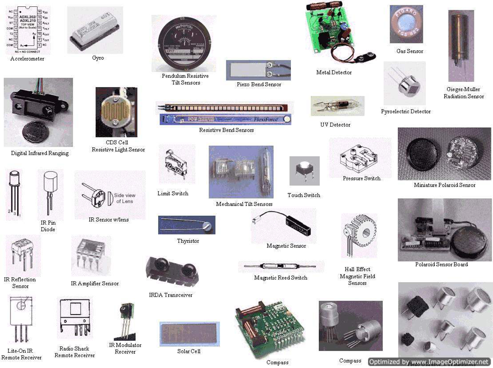
Input Devices: Electronics device which can get analog signal from out side and send to the controller and process it in digital signal (serial monitor in hexadecimal value) it know as input devices. Basically such kind of devices are get data from environment status and doing work as controller programmed language. This types of input devices are know as sensors.
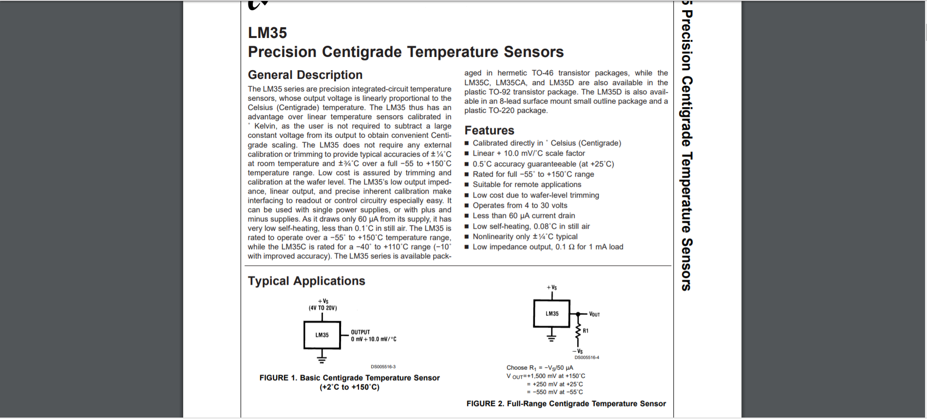
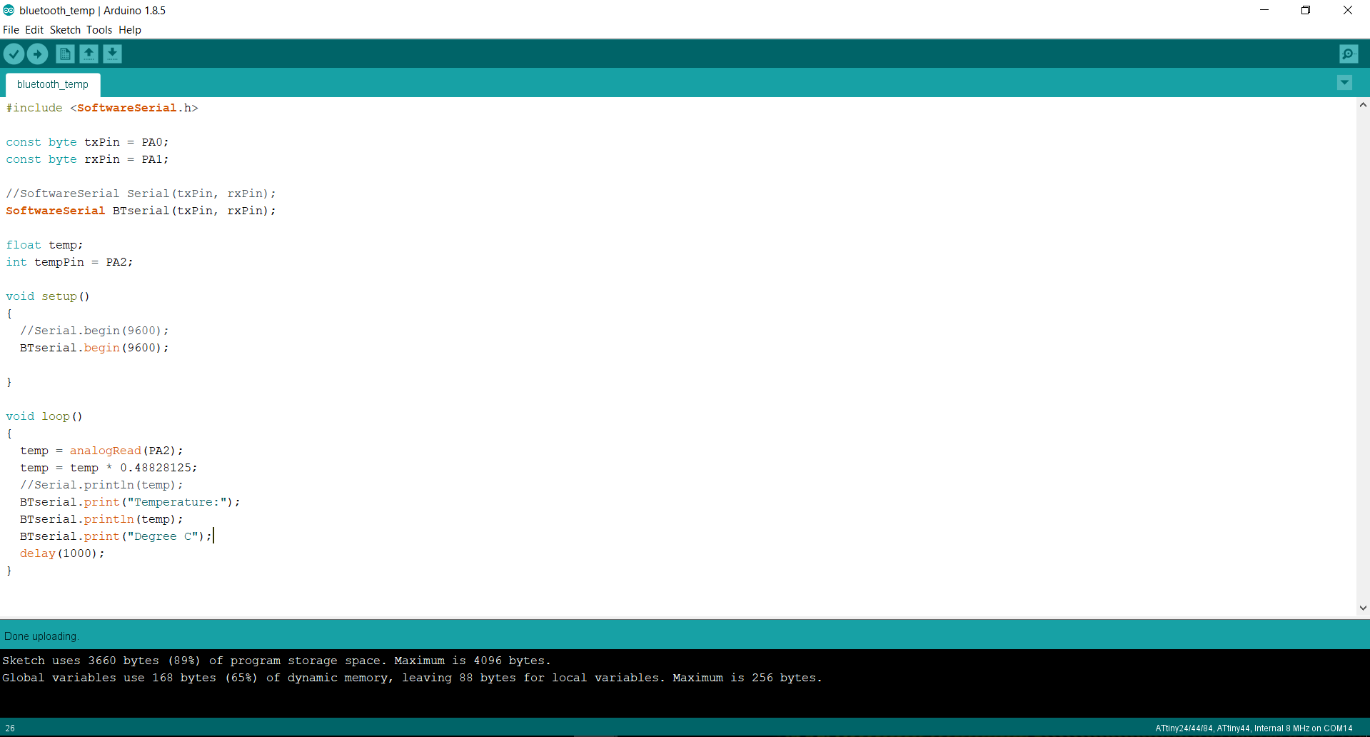
Controller: (ATtiny44) For this week I'm using ATtiny44 micro-controller for controlling the sensor, For my final project i will use temperature sensor (LM35DZ) for detecting the temperature and after get this data out output device will be stops. Before going to schematic design first I read datasheet about ATtiny44 and figure-out how i design my schematic
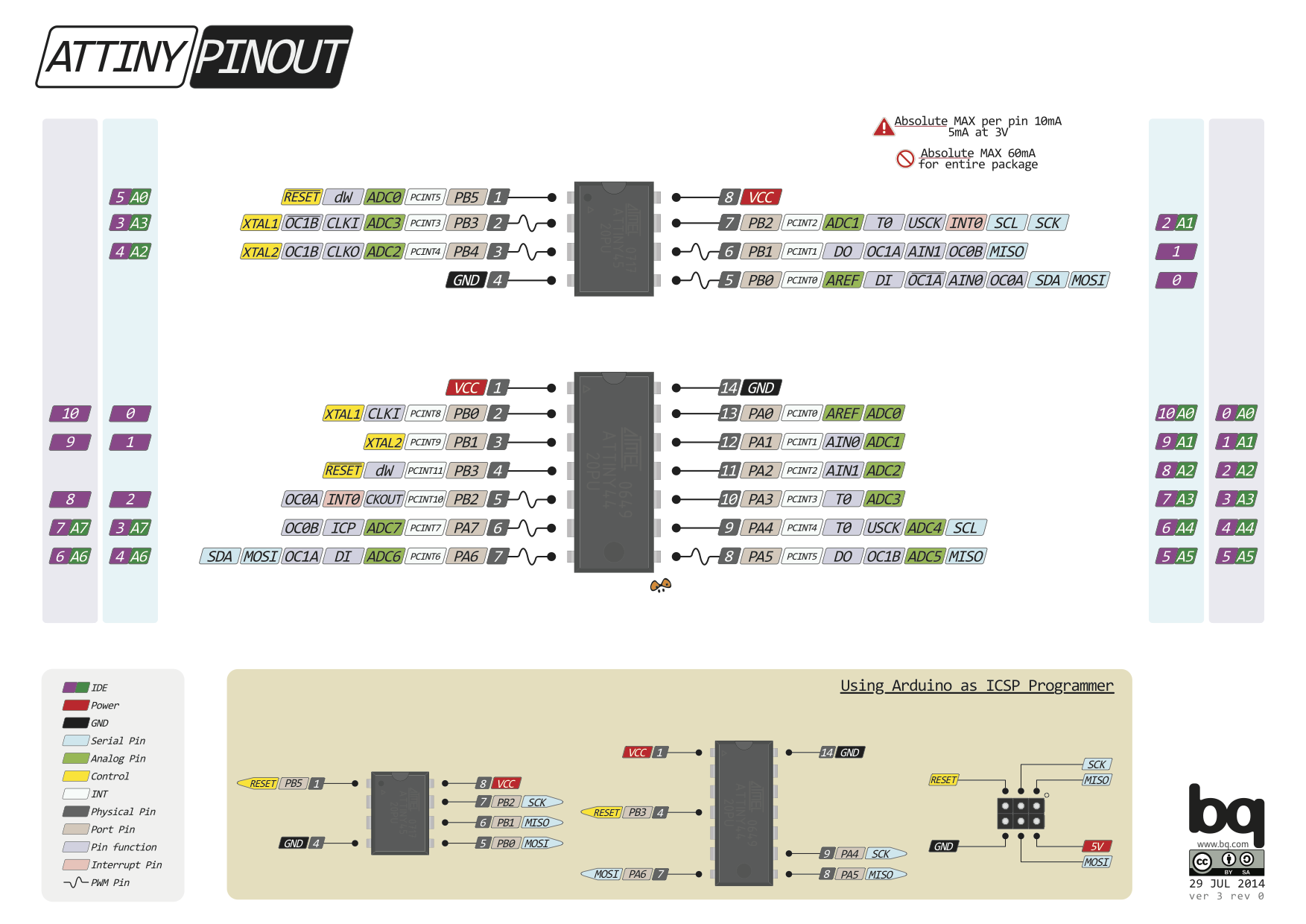
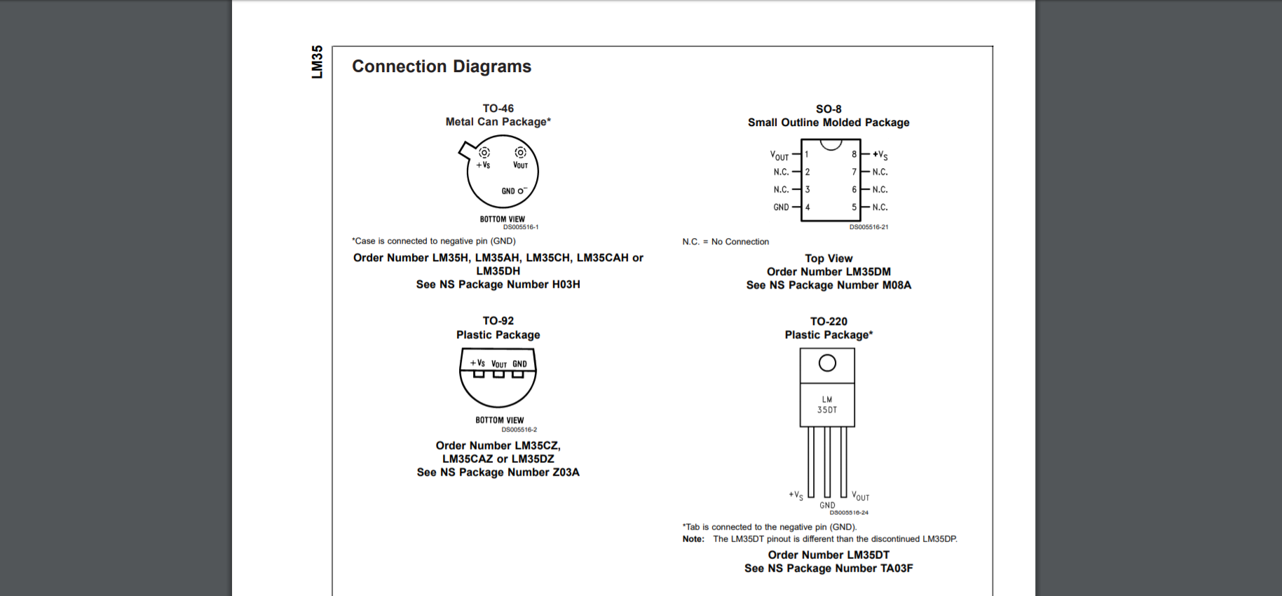
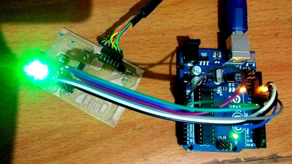
In my input board i connected lm35 (temperature sensor) with PIN no PA2 of ATtiny44 micro-controller. Here first sensor detect the state of temperature and sending the numerical value to the Micro-controller. In input same as i use FTDI where data are sending to the serial monitor of Arduino via TX (PA0) and RX(PA1) serial communication protocol. But here I'm not using serial monitor of Arduino, used the PORT name of the attached with PC in Processing code. The code now detect the data from the sensor which is sending by RX pin.
Before go through this please watch this tutorial about design GUI in Processor. GUI design by Processor
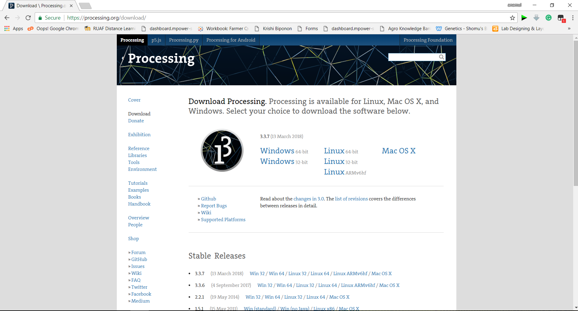
Here I used by Input board for interfacing, I was take attempted to did this by Processing IDE with the serial communication of the Arduino serial monitor. Here I want to show the temperature data using LM35 sensor. First i download and install the processing IDE from the official website.
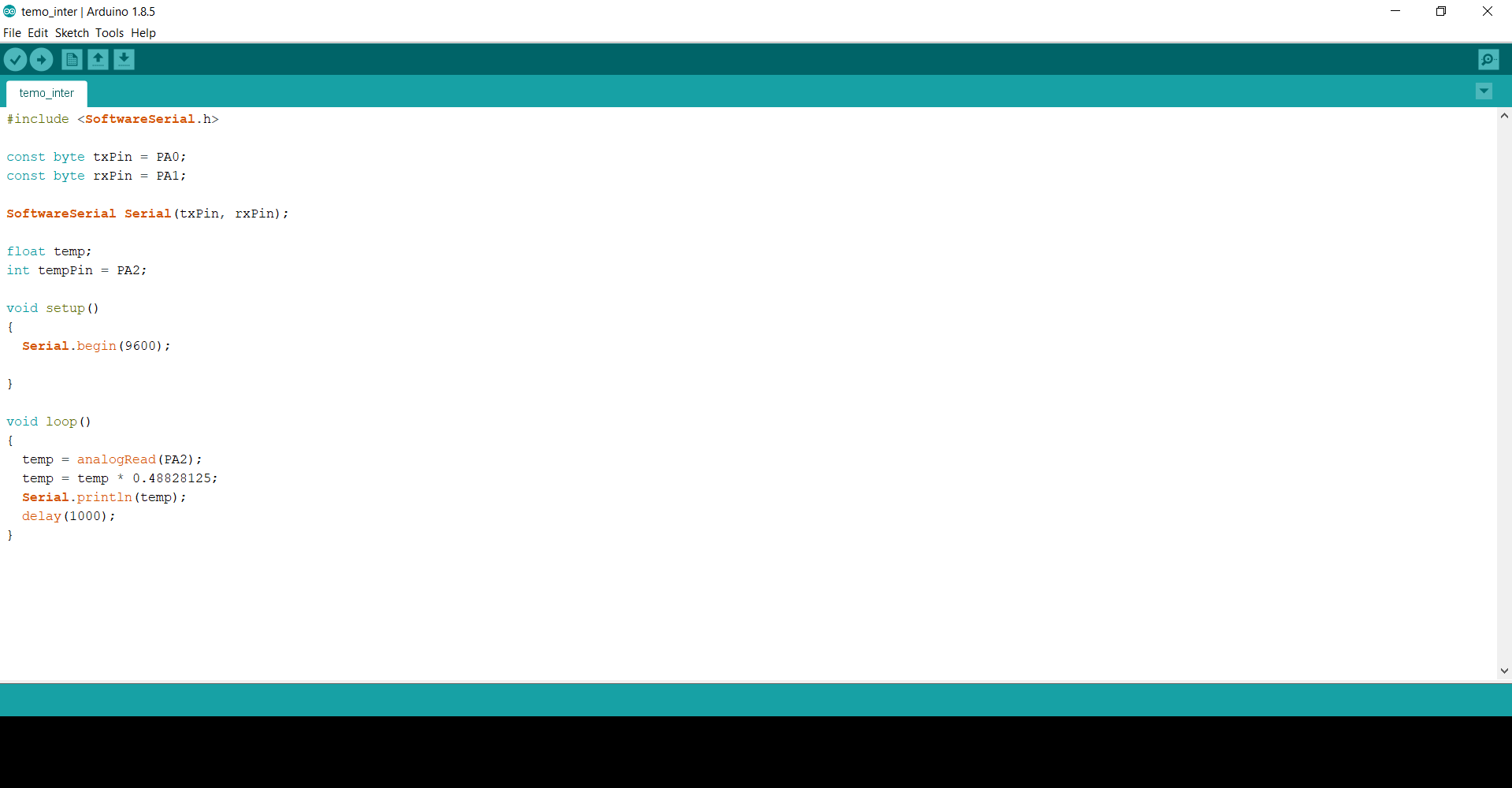
Now I used the same code to run LM35 which I used for temperature reading in Input Devices Assignment. Upload this code to the micro-controller and Check in the Arduino serial monitor(Always Care about serial port in the Arduino IDE tools section for Uploading and serial Monitor in tool menu)
Input board is connected with Arduino UNO and FTDI cable for serial monitor, Arduino used as ISP and connected with PC via "COM14" port and FTDI communicate with PC and board via "COM11" port
In Video show the sensor data in the serial monitor of the Arduino IDE.
Now I was to interface this serial data in GUI (Graphical User Interface). Here they are not try to do something special. It look nice and for Good explanation this GUI is necessaries. For this again i make sketch or coding and run in the processing IDE then its works.
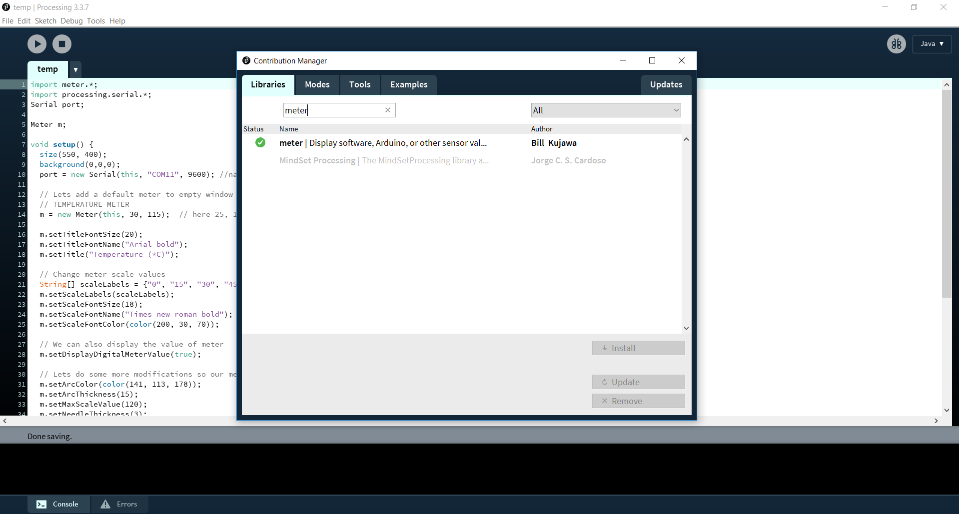
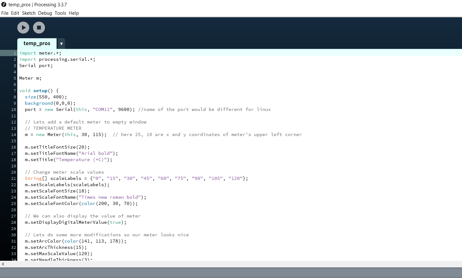
After installation, here I write sketch according my desire how i represent the data, then import the meter GUI library and add in the code.
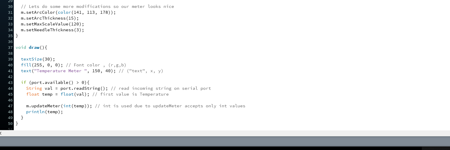
This the view of code and how i represent the void loop and void draw,
Now i connected the processing sketches with COM11 port with serial monitor of the Arduino and then get the data to express it in the GUI platform.
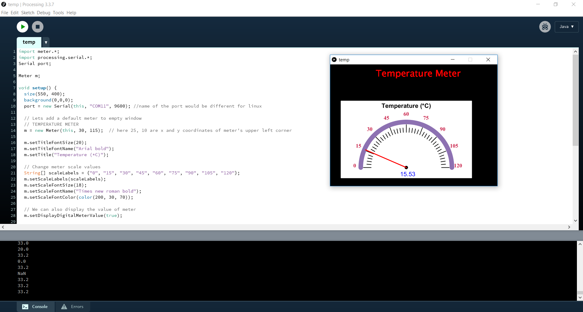
Here I faced one problem that was, if you see the video and here show data in console are reading properly and but accordingly the graphical arc indicator needs to move but is it not, I tried to find out what is the problem but couldn't found. Is anybody can help me out ?
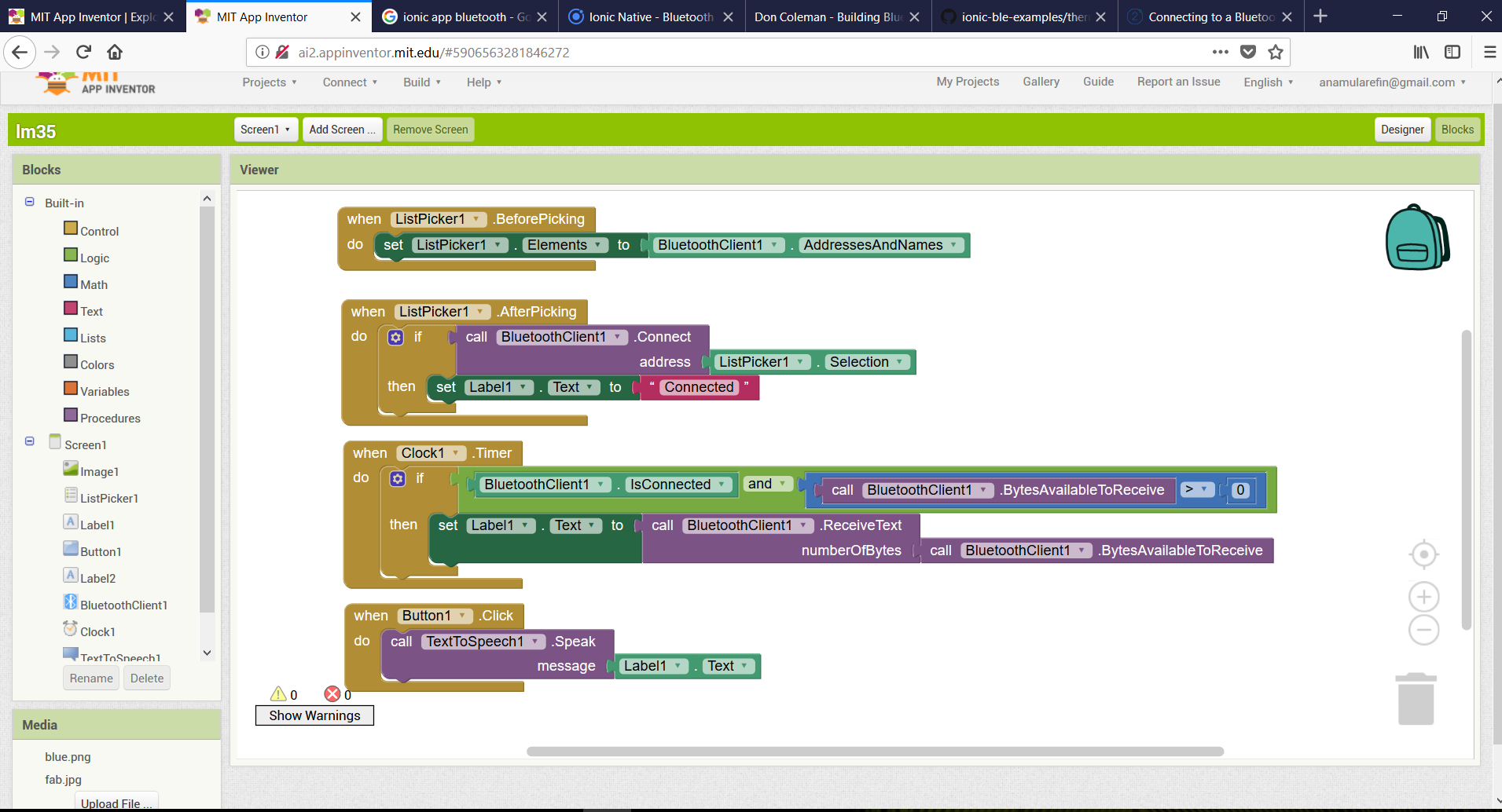
Making Apps in App Inventor
Making the Apps UI in the Design view of the Apps project panel according to the Apps requirement
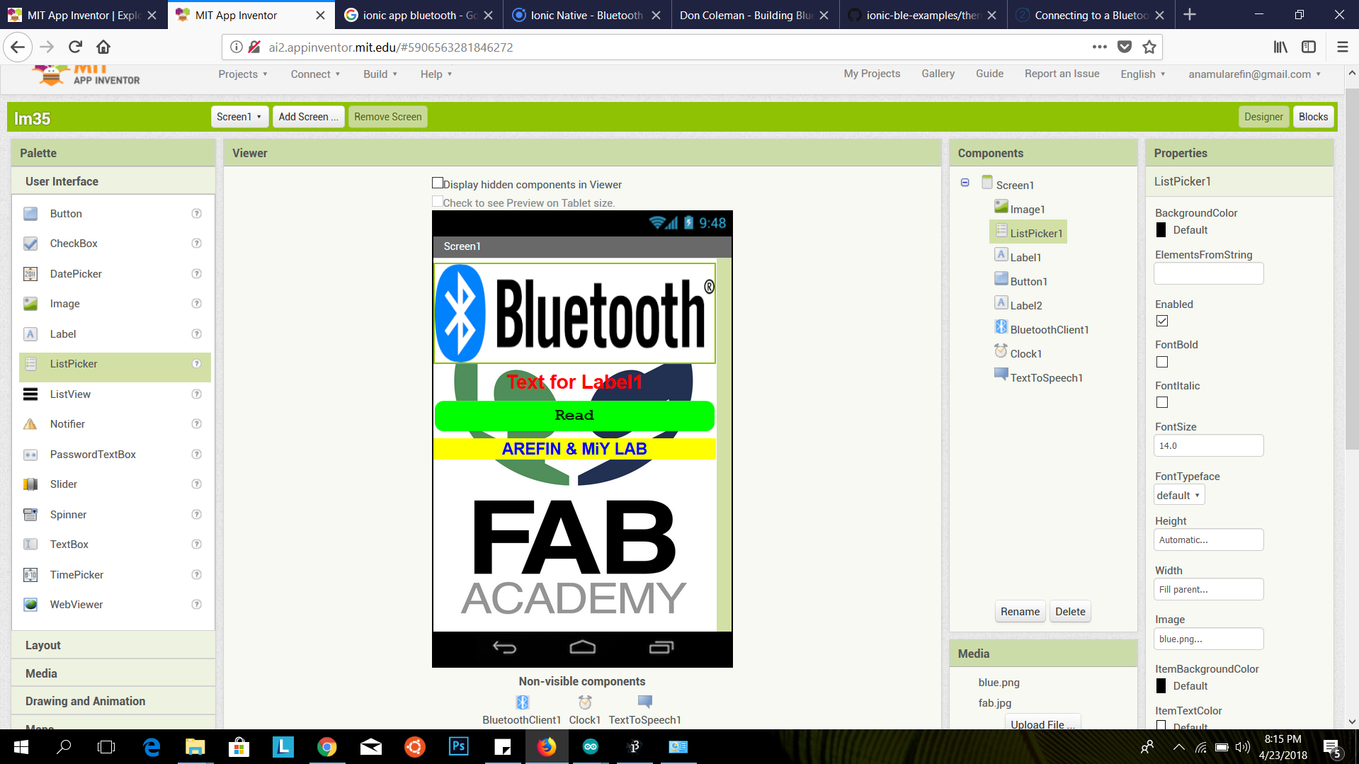
Then make the logic and algorithm in the block view. Here I'm using ListPicker, Button, Label, BluetoothClient, Clock attribute from the left side panel by drag and drop. In Block view i used ListPicker and add inside BluetoothClient as first address. Then again i call it by If/then logic. Now clock1 I call it and being confirm than the bluetoothClient is connected and its getting data. Then it receive the data. After receive the data then talktospeech logic read out this data.
Upload the code in the micro-controller with Arduino Here it's work like the micro-controller sending the data via bluetooth module which is connected with FTDI port of the Input board. I'm using the serial communication protocol with wireless instead of wire. After getting data by mobile where it show in the Apps on the mobile which is pre-design by MIT App Inventor 2.
I connected the my mobile with Bluetooth device as usual system and connect with Apps control panel after, in video:
The Comparison of different process of the interfacing like. If i want to said about serial communication of the input board vai FTDI which means it sending and receiving data by TX and RX pin of the FTDI. After that we visualize it by our own design GUI platform via calling only the "COM PORT NAME". Same thing also in Bluetooth communication where its maintain serial communication but its sending data via bluetooth communication protocol where it show in the bluetooth connected device in designed application.