Electronic Production
- 1. Characterize the PCB Milling Machine
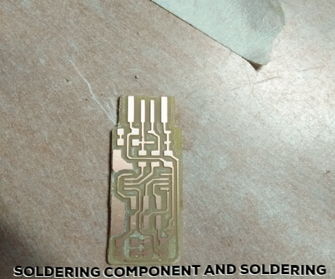
- 2. fabTinyISP PCB Production
- 3. Programming
Electronic Production
Software: For Controlling and giving command on Modela MDX20 we are using Fab Module from Linux system
Hardware: I'm using Roland MDX20 Modela for my PCB making, which has Working area 203.2 x 152.4 mm within the dimension around 476 x 381 x 305 mm, Z stroke is 60.5; Spindle motor 10W DC motor; spindle speed 6500 rpm.
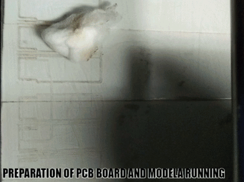
PCB Placing: For placing PCB board on on the Modela working area, first I used foam tape than attached 3mm acrylic sheet. On acrylic sheet I placed the PCB board by double sided tape tightly.Then I tested around the PCB is it fixed or not.
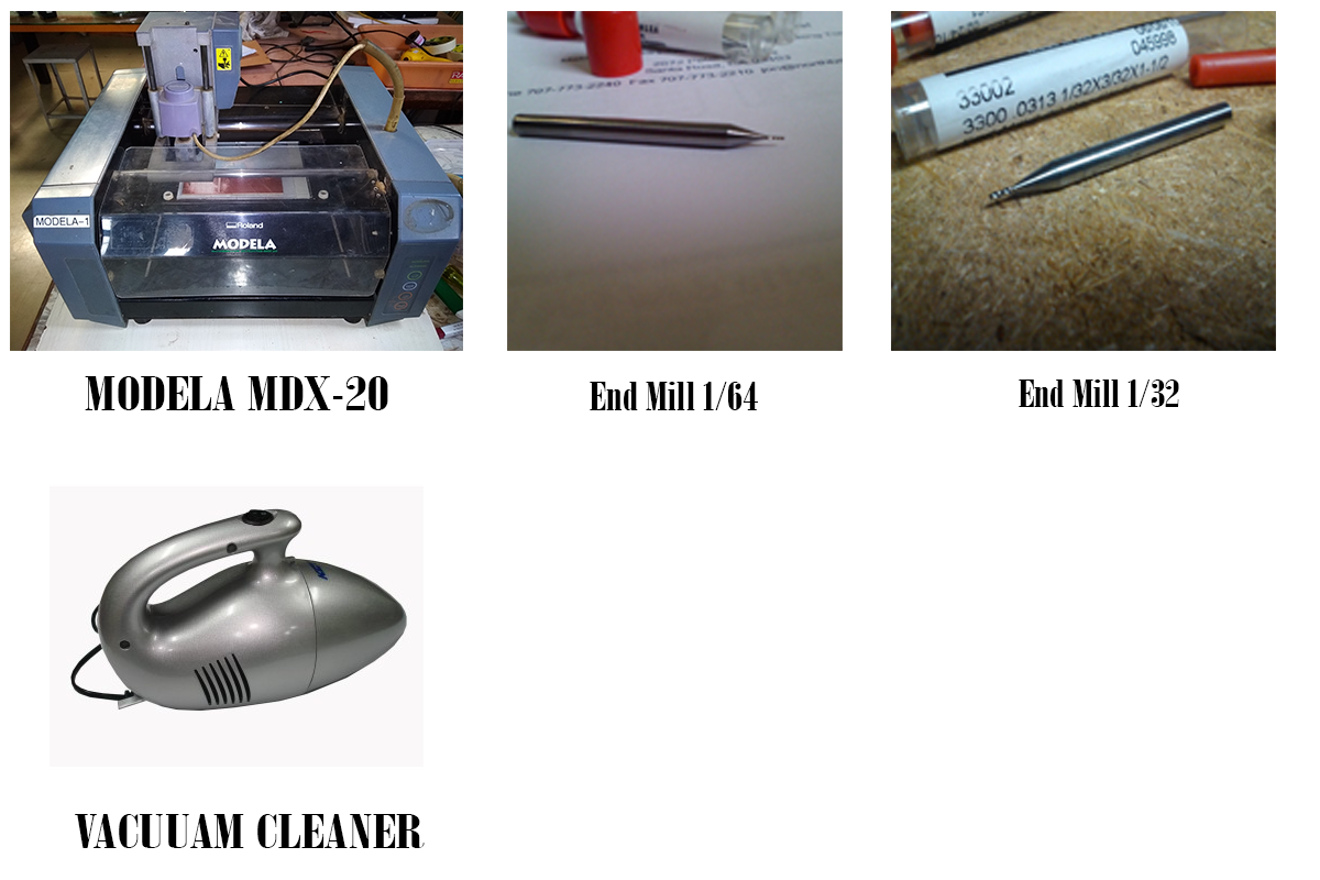
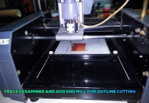
End Mill: For traces on the PCB I used 1/64 end mill which is recommended on this machine cause. By this end mill traces being good. For outline cutting I used 1/32 end mill which is cut the PCB according to the outline.
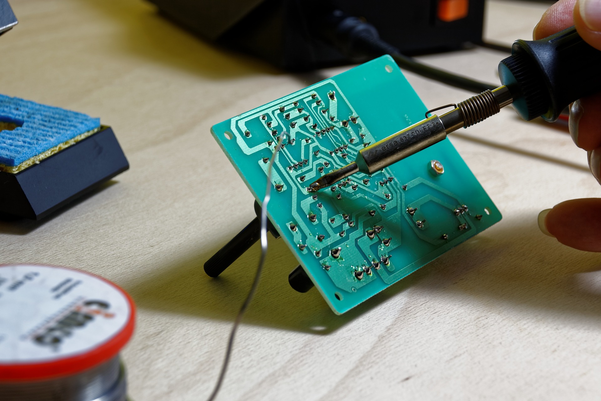
Process: First I set the Origin by pressing VIEW button. Now I check the X/Y placement and set it according to my PCB board placement. After that I check the gravity of end mill of 1/64 which is create outline on the PCB. After examine of the gravity now i tested the screw and tighten it. When the traces are finished then i used vacuum cleaner for sucking the debris of PCB board by pressing VIEW button for lifting board on forward, then check whether the trace is good or not. After completing examine then go for OUTLINE cutting, for that i change the end mill 1/32 and the place the bit as previous position of the PCB followed the gravity test and go for cut. As usual I use vacuum cleaner for cleaning the debris and finally I get my PCB
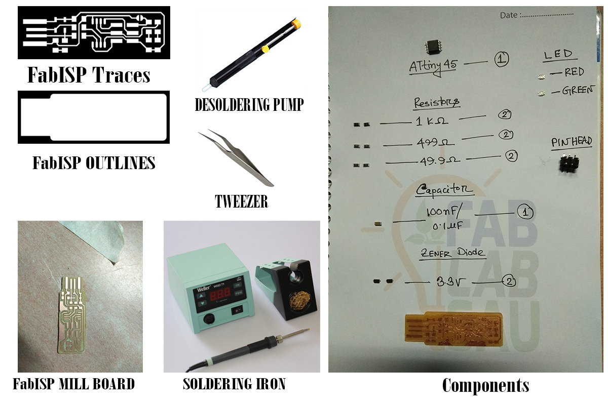
This week I'm going to make a common PCB board for making a programmer called fabTinyISP. I collected the PCB traces and outline from the weekly assignment named:Electronics Production in this assignment here you go this link to download Brain Board for fabTinyISP PCB production is the 4 steps process
First I going to program on Windows machine, for program on windows i used git bash for command and controlling the board. I follow the two tutorial like fab TinyISP then for process i followed USBasp on Windows for detecting the USBasp on windows i also try driver to install and i got it from this site USBasp on Windows but is not detecting after completing the installation. Check the images in below:
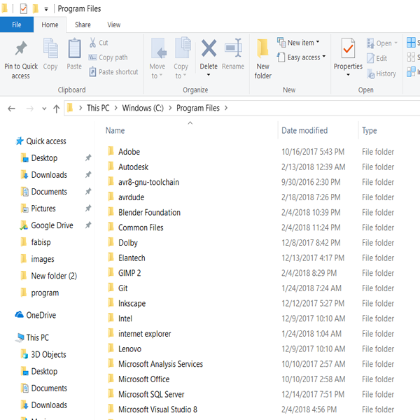
Installation: For programming on windows I install 4 different software like a. Make.exe 2. avrdude 3. avr8-gnu-toolchain-installer-3.5.4.91-win32.any.x86.exe 4. zadig and download firmware_45 to store all data.
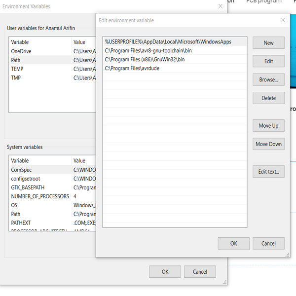
user variable path: After installation it mandatory to write the every software user variable path in the windows environment variable.
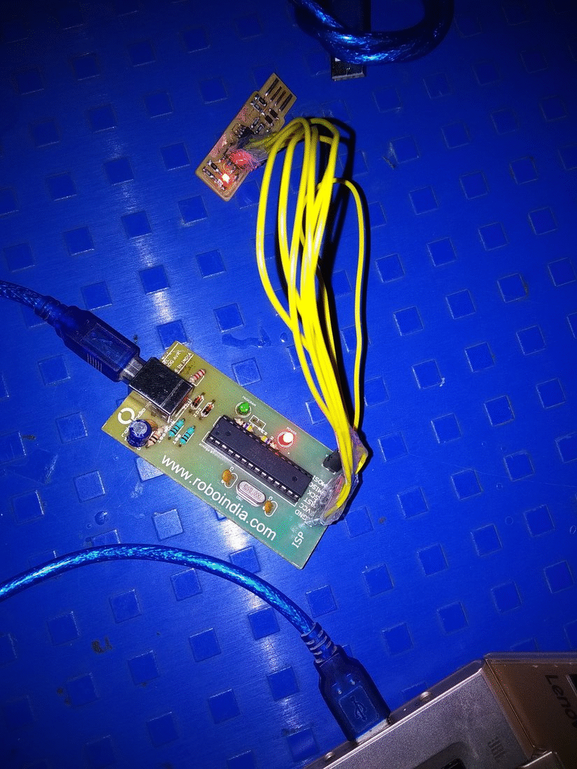
Wiring on programmer to USbasp: Careful! this is the important part for ISP pin to attached with the programmer board as pin1=MISO; pin2=VCC/Vpprog; pin3=SCK; pin4=MOSI; pin5=RST; pin6=GND; follow this pin out and connect with USBasp and programmer.
GIT Bash on Windows: After that I used git bash for control the command of board. then send command like 1. Make -v for version checking the make.exe; 2. avr -gcc --version 3. avrdude -c usbasp -p t45 4. make flash for flashes all data 5. make fuses.

I used some command for programming the board where is follow:
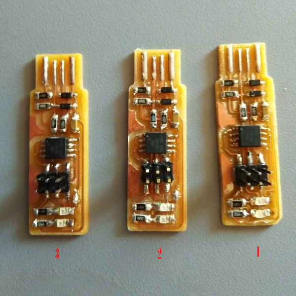
First I going to program by 2. board which is programmed well but not detected in PC. After that I tried within one hour but could find any problem, then i shifted my another board 1. which is programmed well and detected by PC and Linux both.
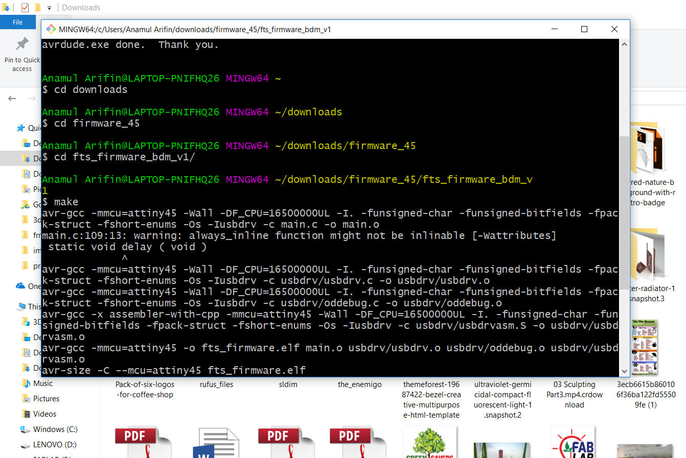
Enter the directory file of firmware
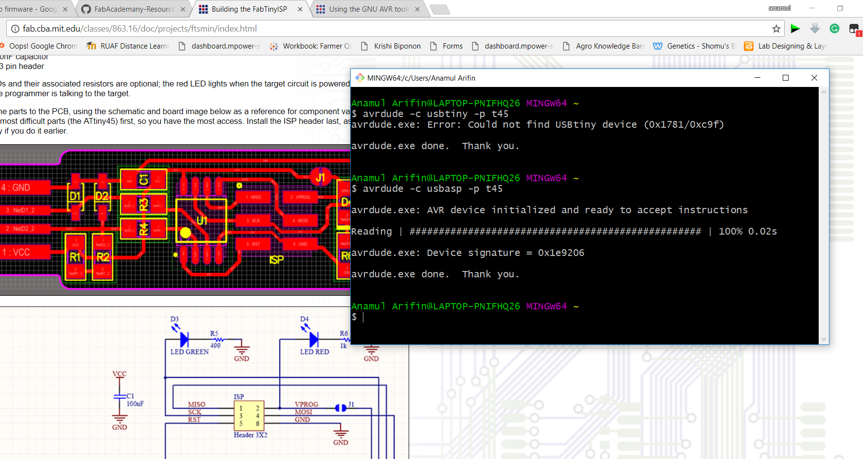
Detecting the USBasp by Programmer
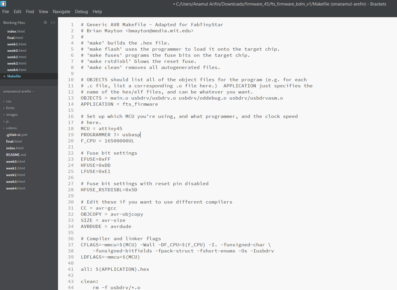
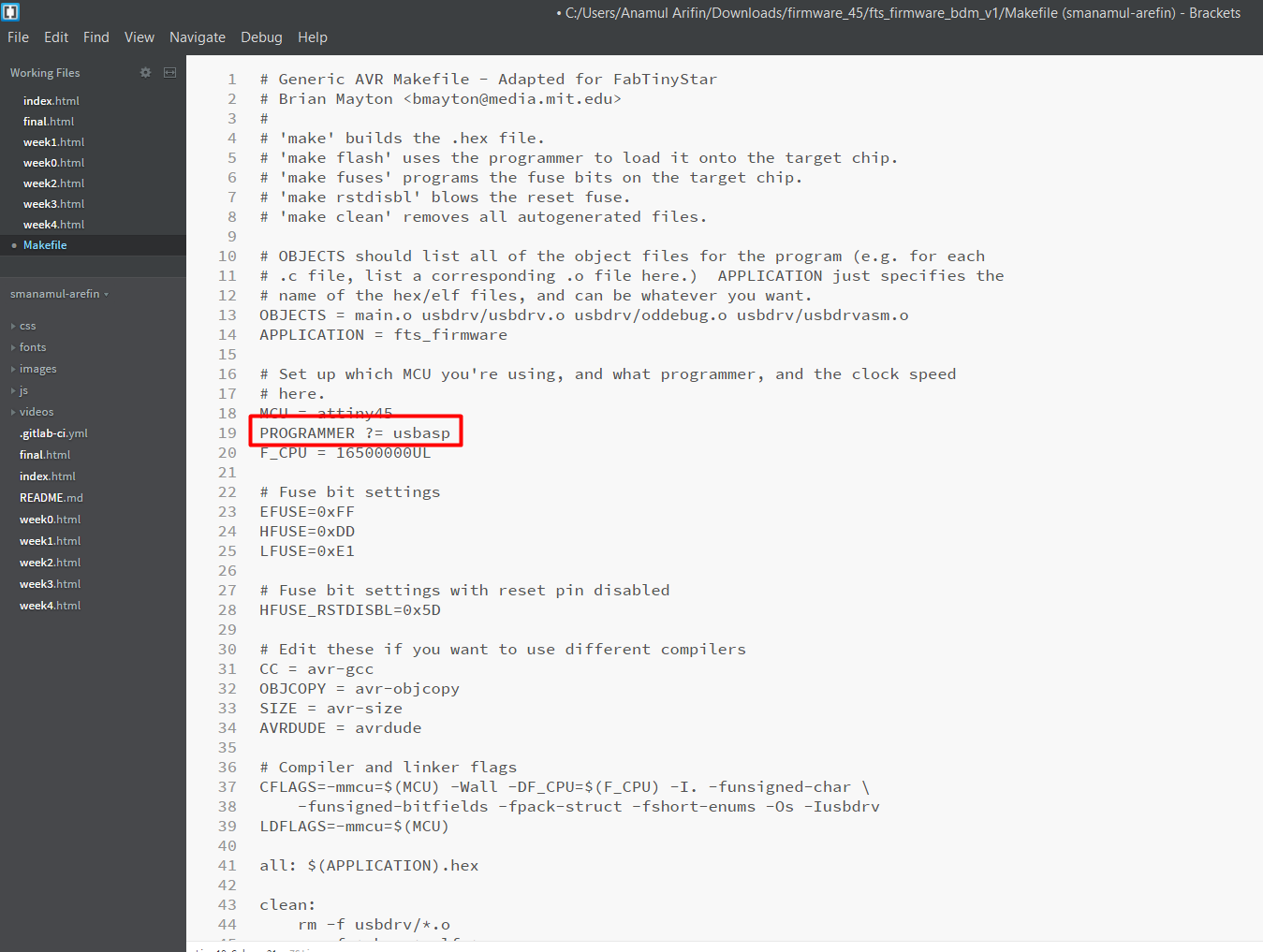
Change the programmer in make file
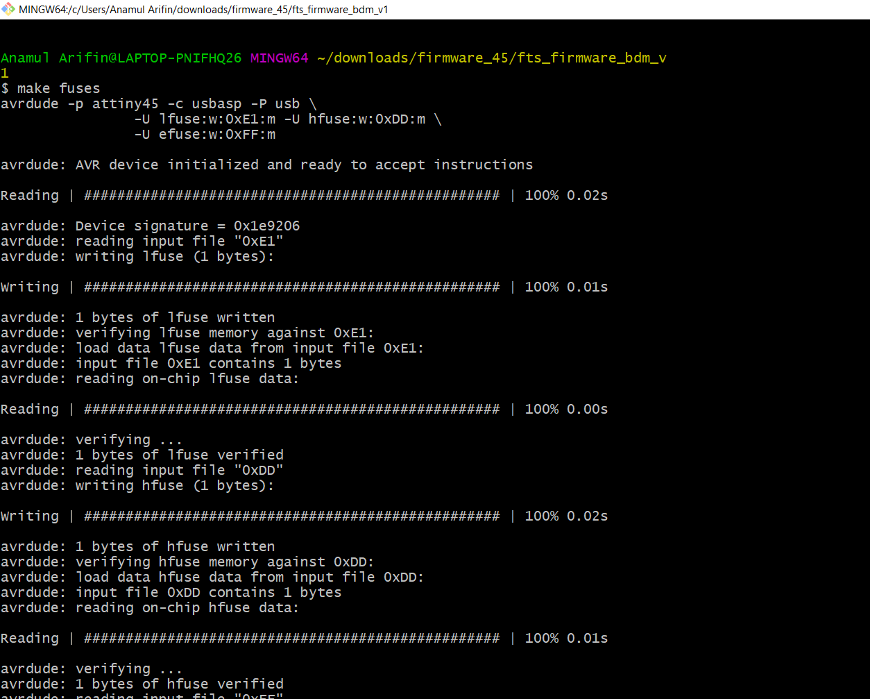
Finally its going to programmed