
Computer-Controlled Machining
- 1.Make Something BIG
- 2. Group Assignment: Alignment, Feed Rate, spindle Test, Bit check etc
Computer-Controlled Machining
Computer Controlled Machining
Basic Info about shopbot PRSAlpha: The ShopBot PRS Alpha is a CNC machine that allows users to cut, drill, carve and machine wood, plastic, aluminum and other materials along 3 axes, X, Y, & Z.
Specification: Table Cutting Dimensions: 69 inches x 96 inches; Table Area: 6624 square inches = 46 square feet; Table Thickness: 0.75" Plywood Bottom Layer, 0.75" MDF Top Layer
Jog Spindle : 30”(760mm) per second
Toolpath: 220V 20A for Controls/ Router (Spindle amperage requirements vary on horsepower and voltage)
Software Basic : PartWorks for making toolpaths and sending Gcode machine used Shopbot 3.
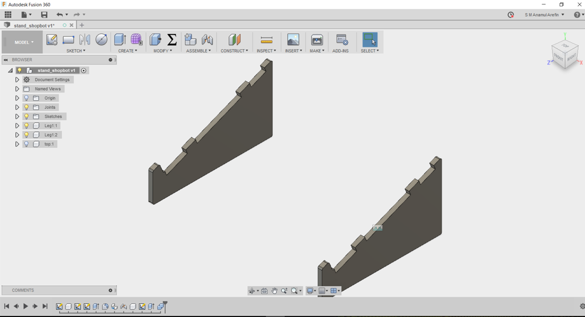
3D Design: For make something big assignment, i don't make a big staff, for this i make a small project like laptop stand. for making this I used the fusion 360 software and follow the youtube tutorials to making. Actually I focus on the how much learn in using shopbot, not in making any big things. My Designing process are given below:
1. First I made the sidebar and copy it as new with fix the length as parametric units.
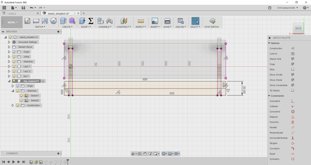
2. Then I made top plane with project option in the side bar and completely fix the press-fit part with sidebar and top parts.
3. Then I made the support for the stand and fix it in two side.
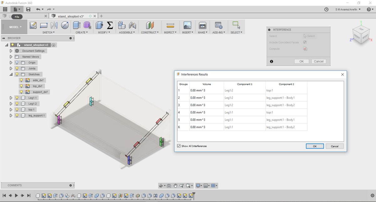
Finally I made this stand, I check the Interference how it fit with each component.
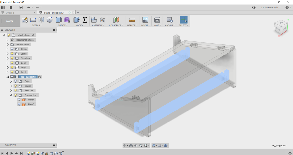
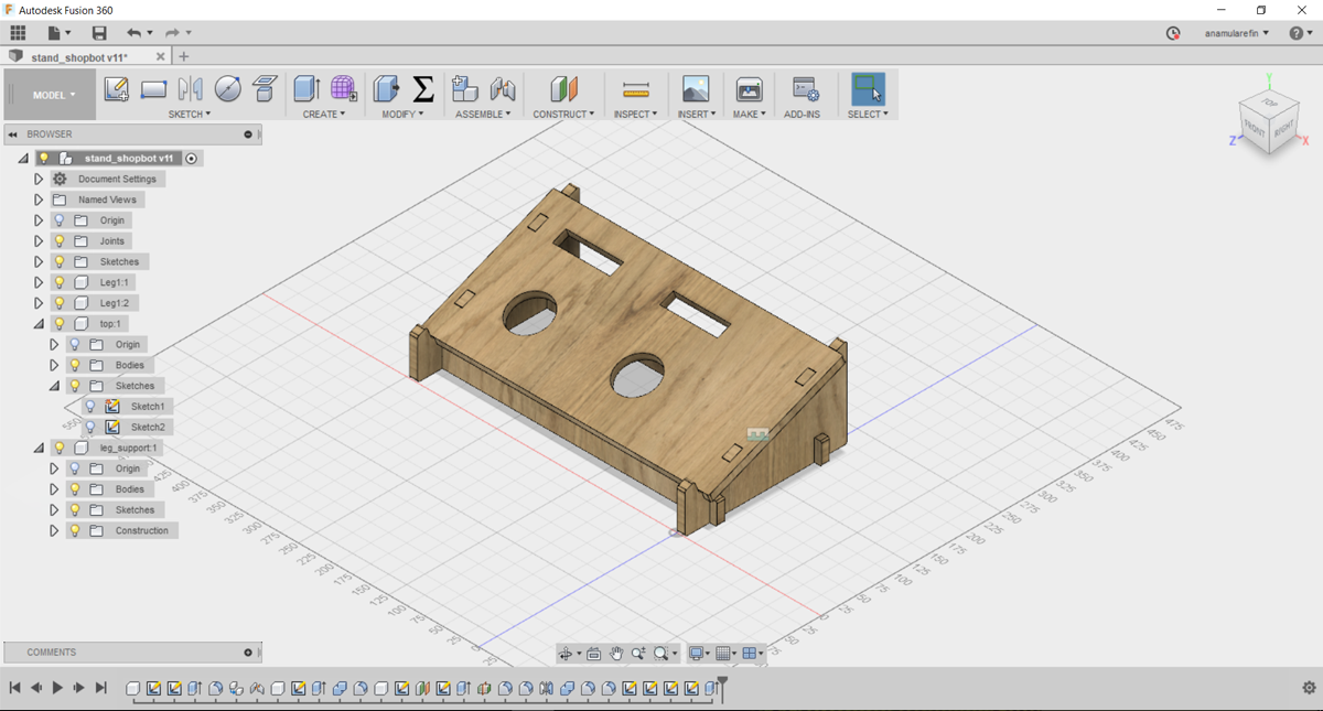
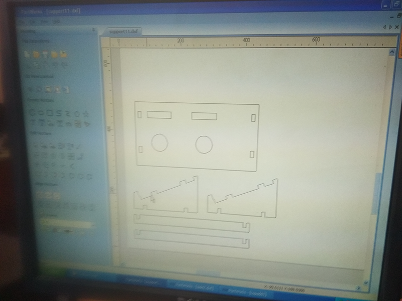
Finally I made this stand, and export the dxf file for cutting.
Shopbot Used and cutting the design:
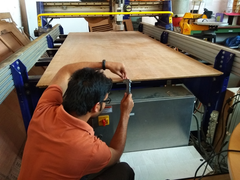
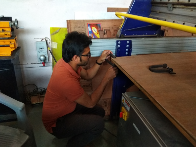
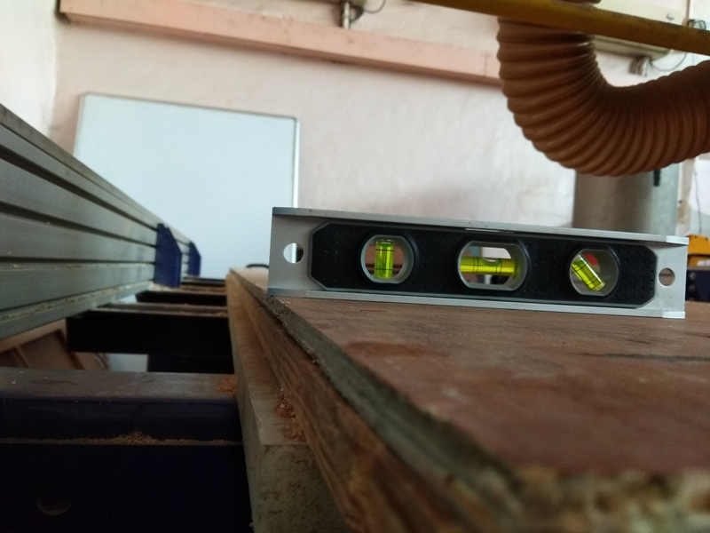
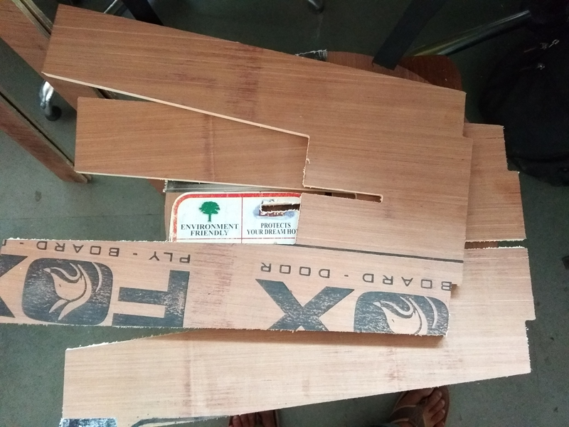
First I measure my board which i used to cut and then I check the alignment of the board, but this is not properly align.
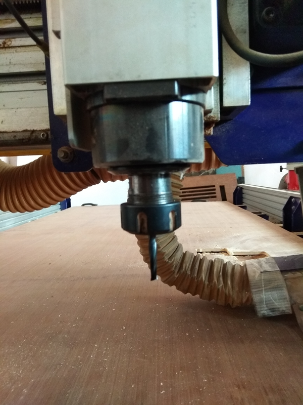
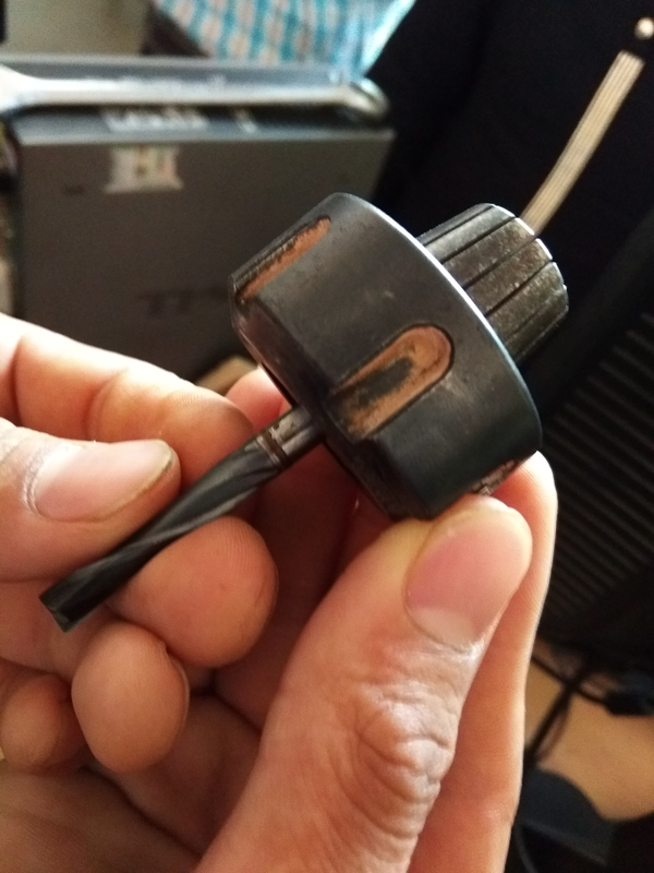
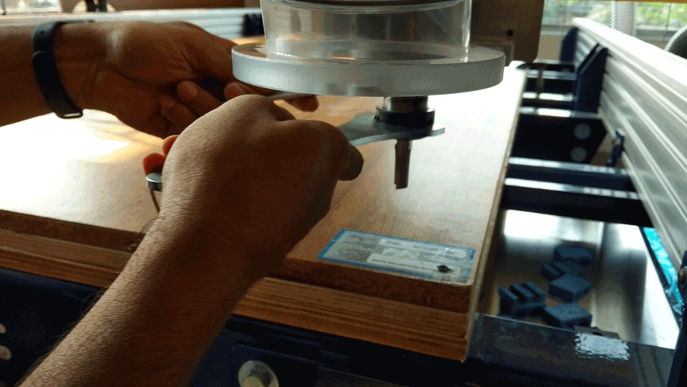
Then i fix the Collet and bit with the spindle and and check the thump knock to attached the dust panel. then fix the board with screfacial layer with clump
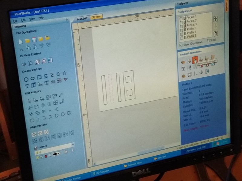
Now I making the toolpath using PartWorks software, making profile cut first inside toolpath and then outside toolpath. then i set spindle speed 12000 rpm/min, and feed rate 0.1 with 37% inch with stepover 27 and passing depth 3 mm/sec
Then start the shopbot 3 software and setting up the origin first, using the arrow key from the keyboard, and page up/down for z axis. and the use zero axis. Then loading the toolpath file in the shopbot 3 software which is read it as gcode. Then I start by pressing it and ok from the software option.
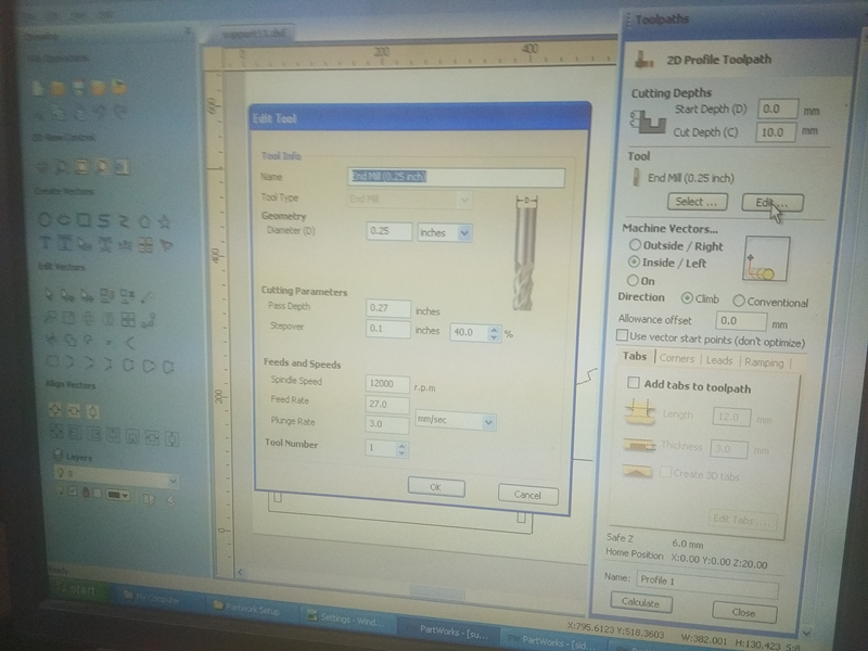
Here I setup the endmill 0.25inch where as pass depth 0.27 with the spindle speed 12000 and feed rate 27, I saw one thing in upgrade version of the shopbot, if i select endmill it select default all other speed and feed rate, just i can maintain pass depth according to the materials depth.
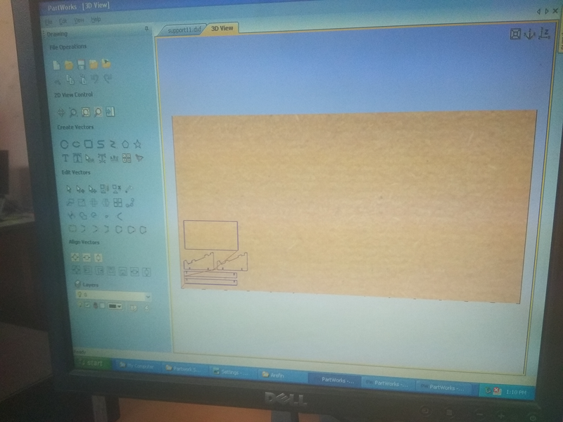
In partworks it show the toolpath direction of the cutting, how the endmill are pass through in the board
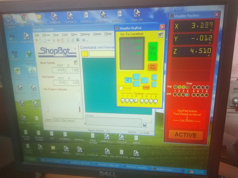
Control panel of the shopbot, by pressing K from keyboard keypanel are open control the movement of the X, Y and Z axis by manually for setting up zero.
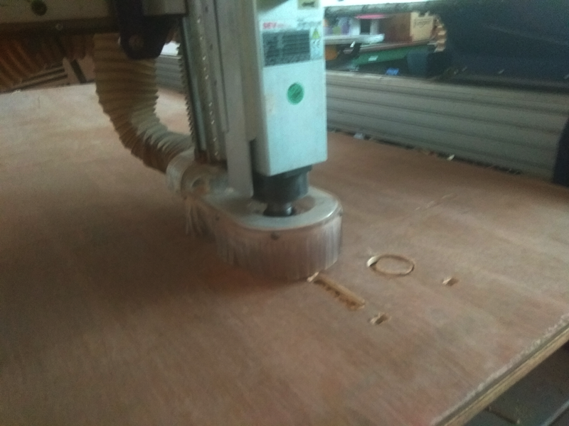
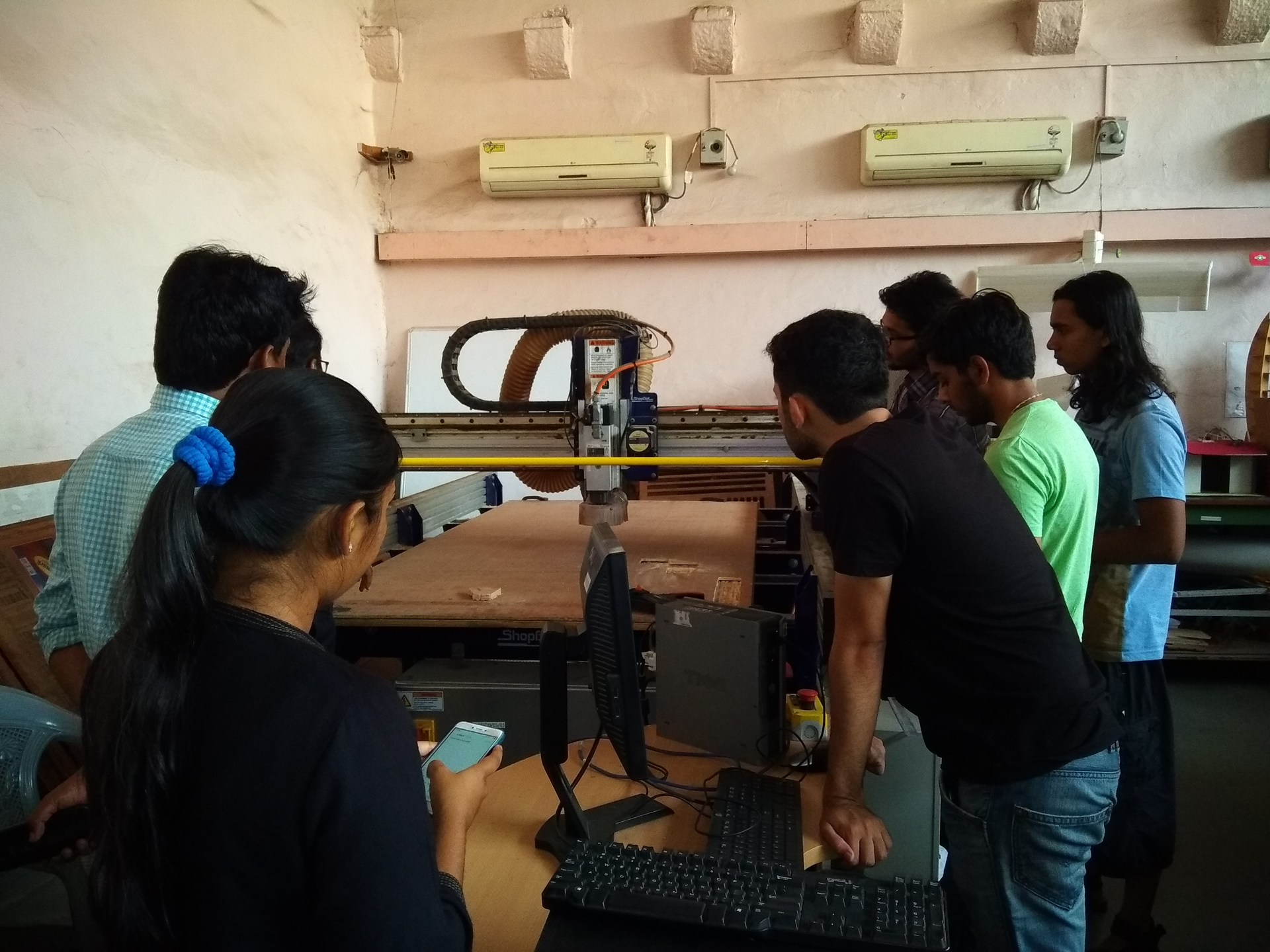
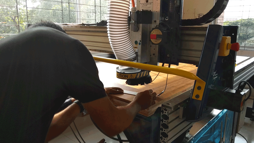
Shopbot now in operation.

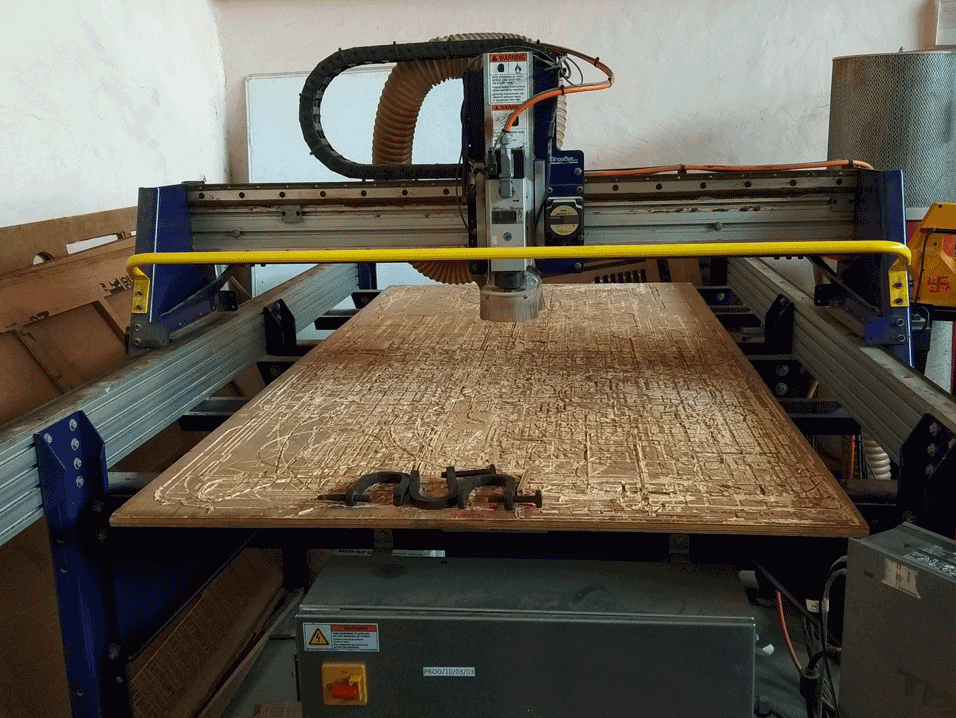
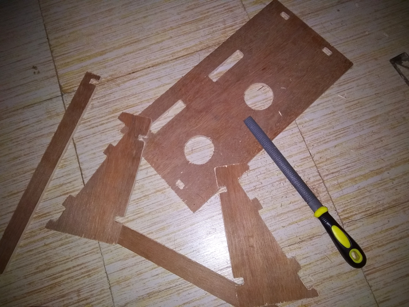
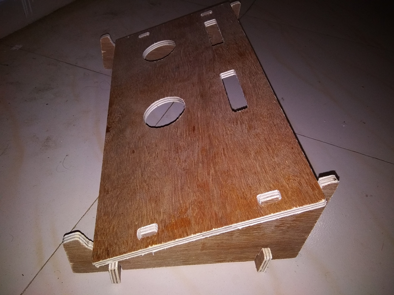
After cutting the board are looking like
Problem I faced: After cutting I checked my cutting sample where my design has 11mm after cutting it show 10mm which is not properly press fit cause the alignment issue which was i mention in first.
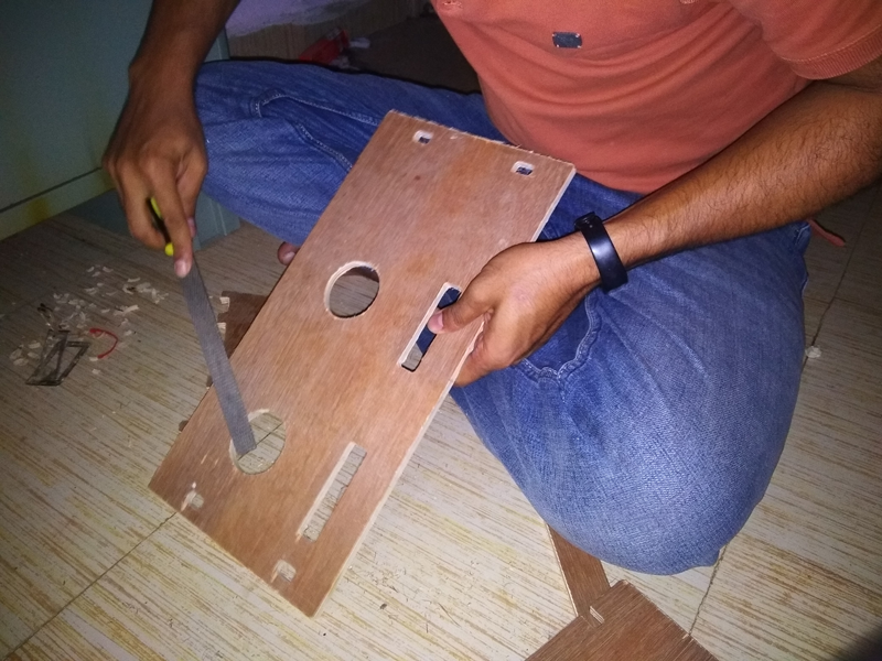
Assembly: Then I assembly my design some part need to filing in edge, other part i used fevicol synthetic wood glue for fix attached.
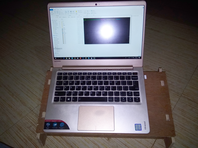
Finally I attached the all parts and i checked the stand by using it. it looking cool
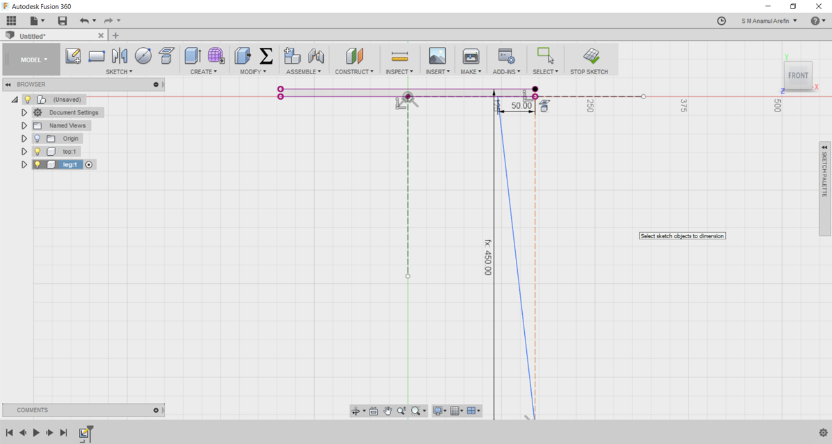
3D Design: I make a another design about to making stool for fablab. For designing here i also use fusion 360. My Designing process are given below:
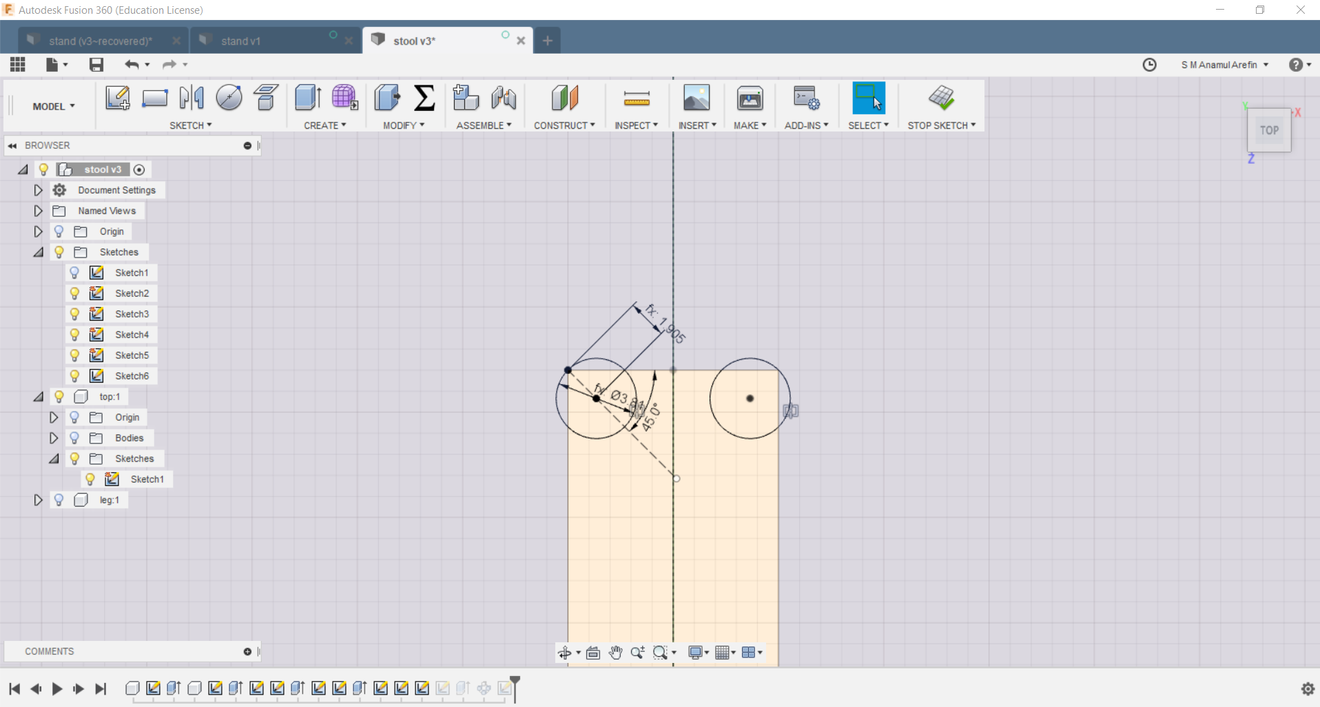
1. First I made the top and copy it as new with fix the diameter as parametric units.
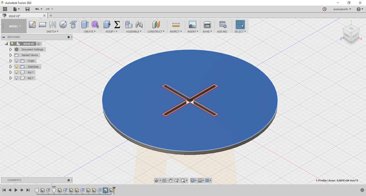
2. Then i made the stand with parametric units and fit with top
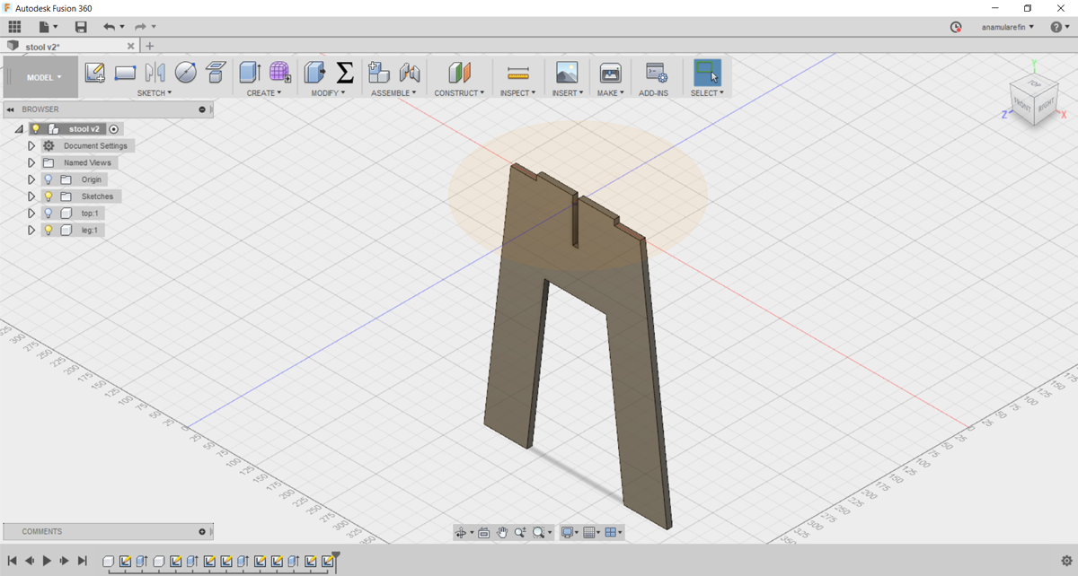
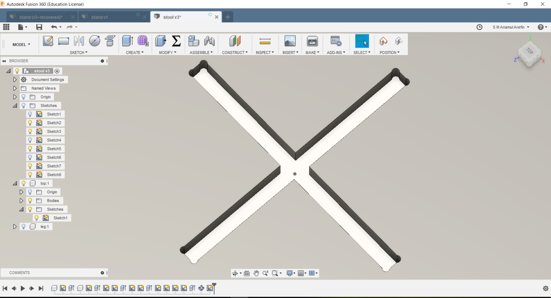
3D extrude view of the stool
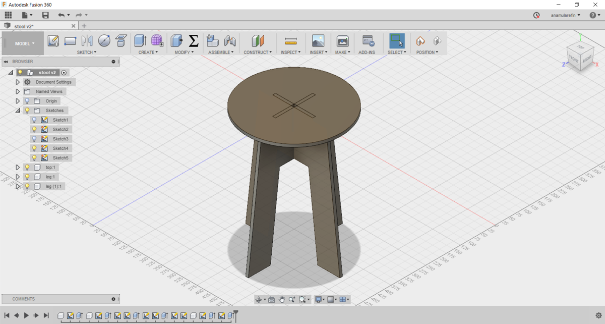
3. Then i finally made this stand
For making this design i follow this tutorial
Cutting:
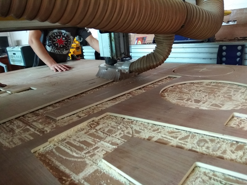
After cutting the board i used sand file for sanding the edge of plyboard, In my design I didn't used dogbone design that's why it's hard to attached the board in slot according to the design.
I have little bit knowledge about dogbone design, I heard about this in a tutorial of flat stool making in youtube.
In my global evaluator also send me this link Dogbone From here i learn so important information about dogbone. In my next design I hope to add dohbone design and check the cutting process according to the design.
In above website I learn about dogbone and how i measure it and what is the appropriate dogbone for proper fixing the board.
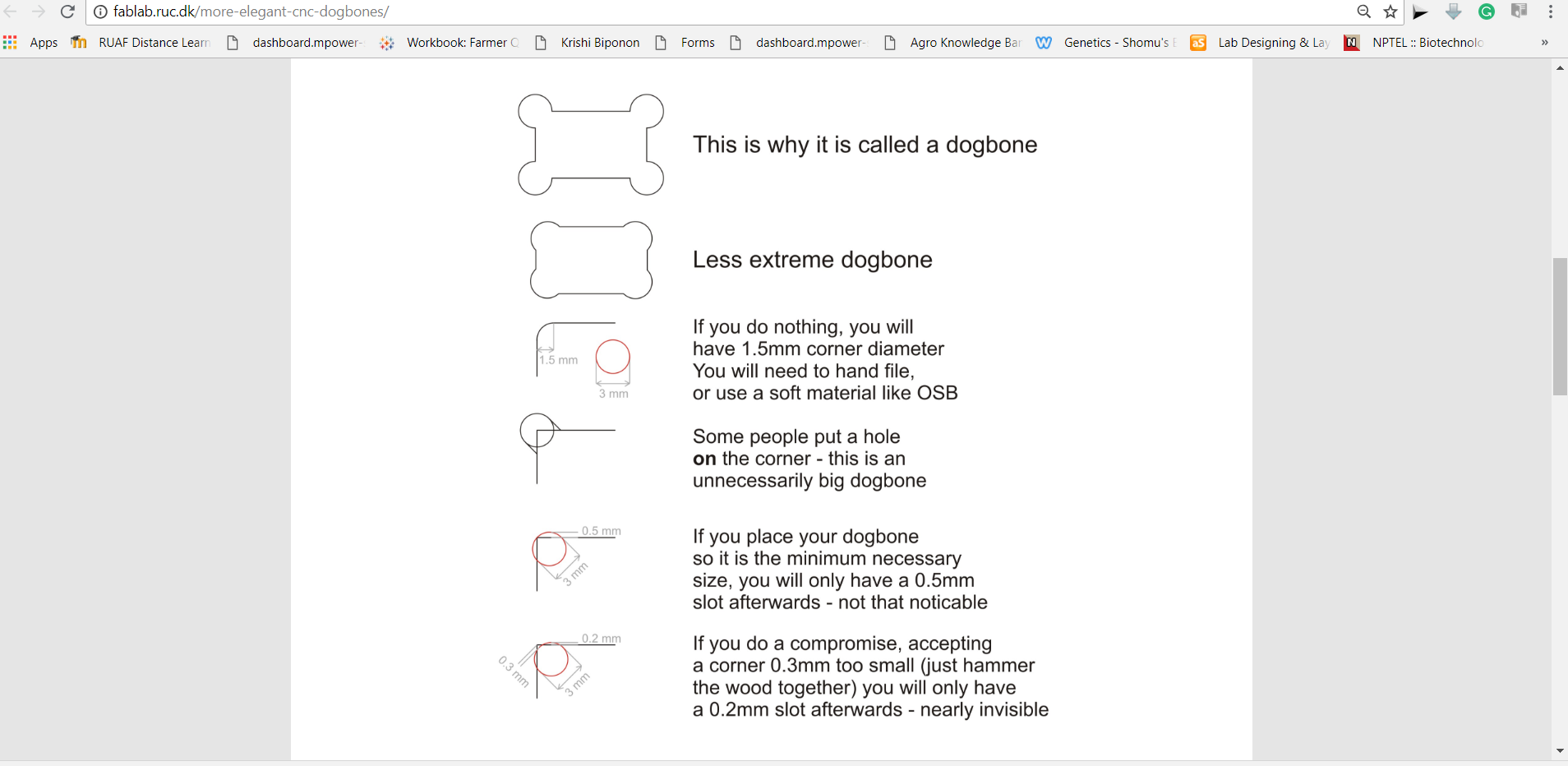
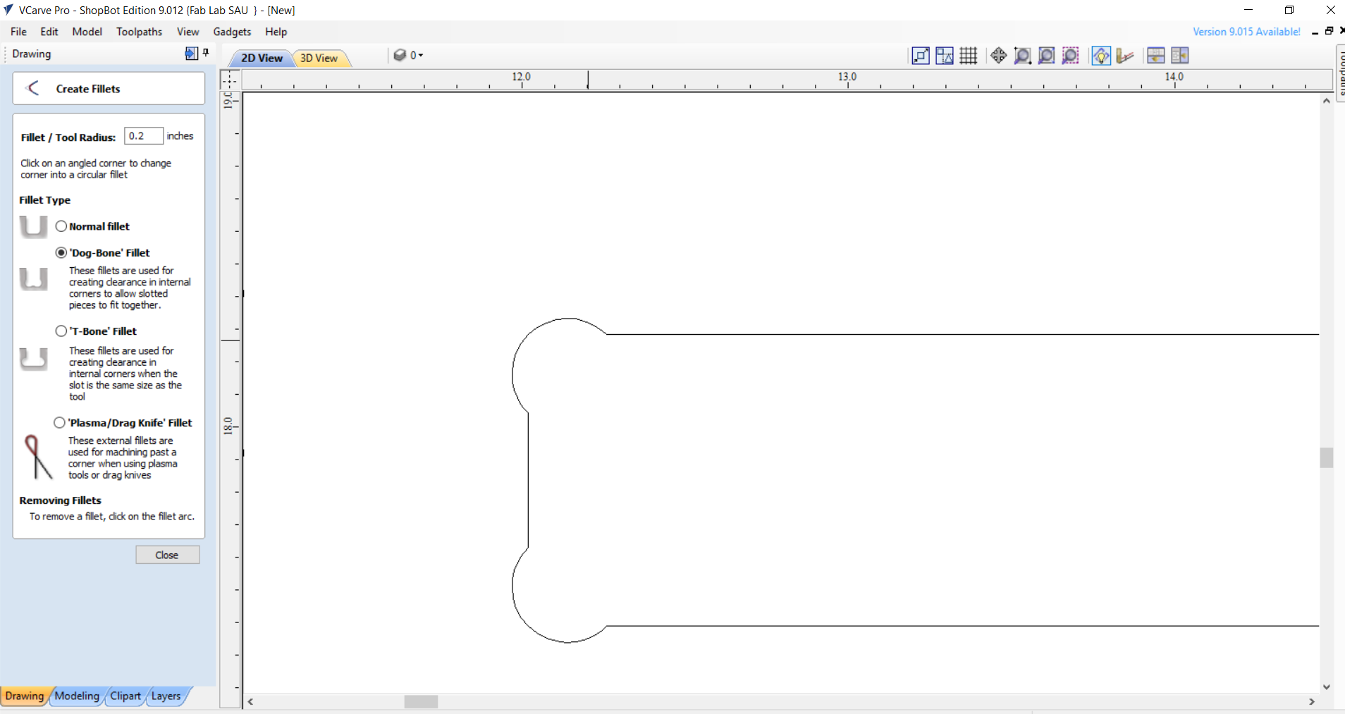
In my design I'm not used dogbone but i learn about and try to design a dogbone in corner of the design.
In 3D view here is the dogbone design
After DXF format I import it too vCurve with the fillet curve design
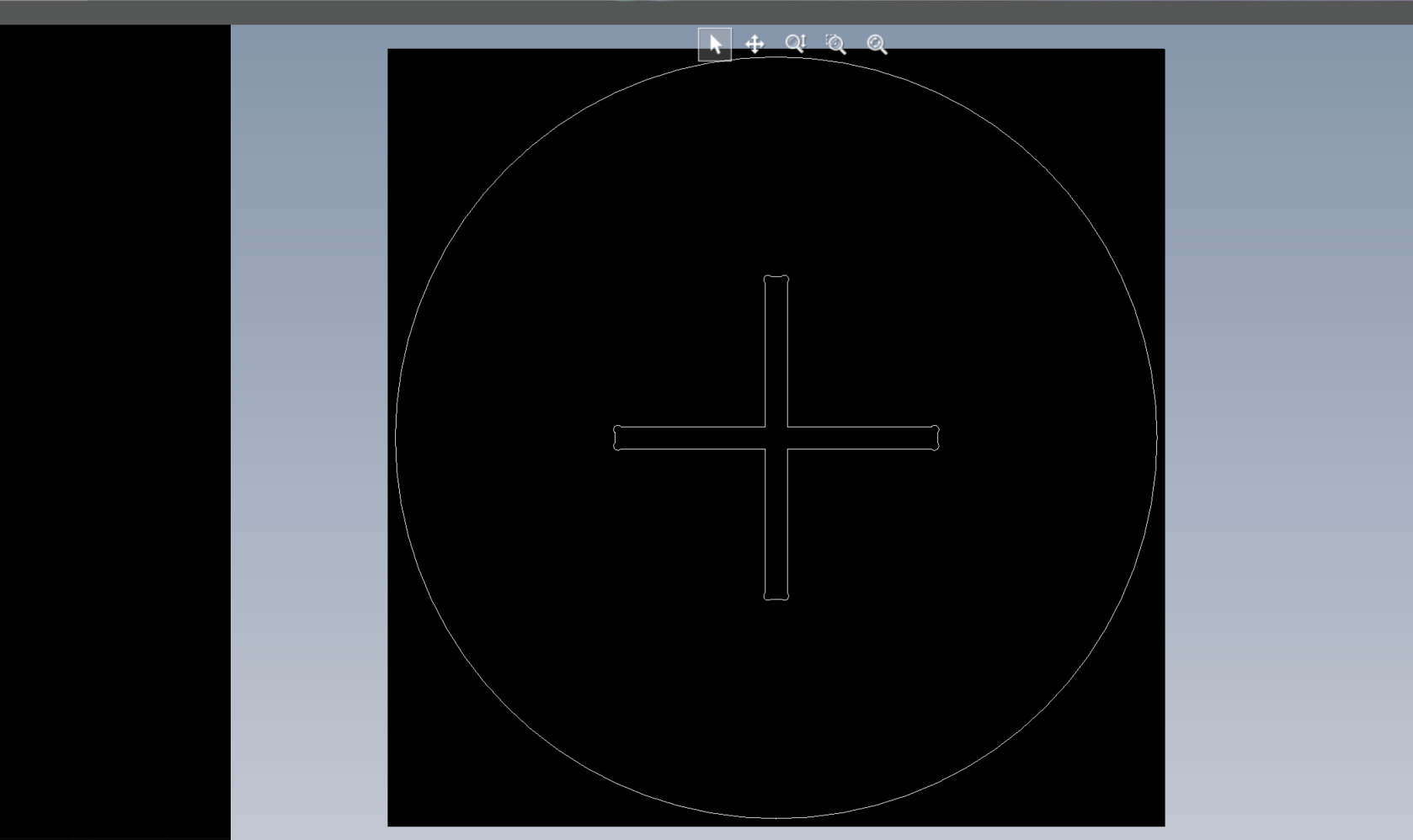
In vCurve here I show the fillet design about dogbone design
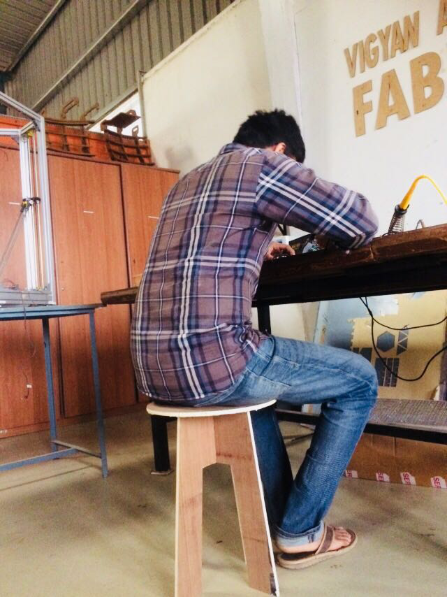
After that I assembly my design and here I represent the stool
Here I lost some photo from my mobile, that's why I'm not share this images

After assembly I sit here and then I also working in electronic lab sit on it.
For group testing we are doing some test like: alignment, toolpath making, spindle test in different speed
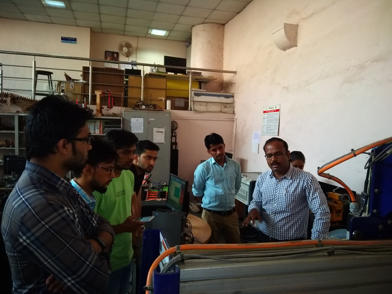
Alignment Test: For alignment test we are using labeler for checking the alignment for working board, but we found that the machine has some alignment problem that's why it taking 1-2mm kerf/offset less cut from actual design.
End Mill Setting: We open the end-mill from spindle and then check how it fix, then again attached with spindle
Endmill with collet
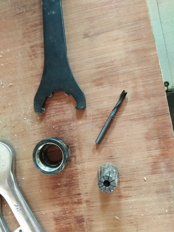
Endmill, collect and ranch
Toolpath Making: Then we doing toolpath making by partworks software, we check the two different design, one for pocket and another for outside cutting line in different spindle speed.
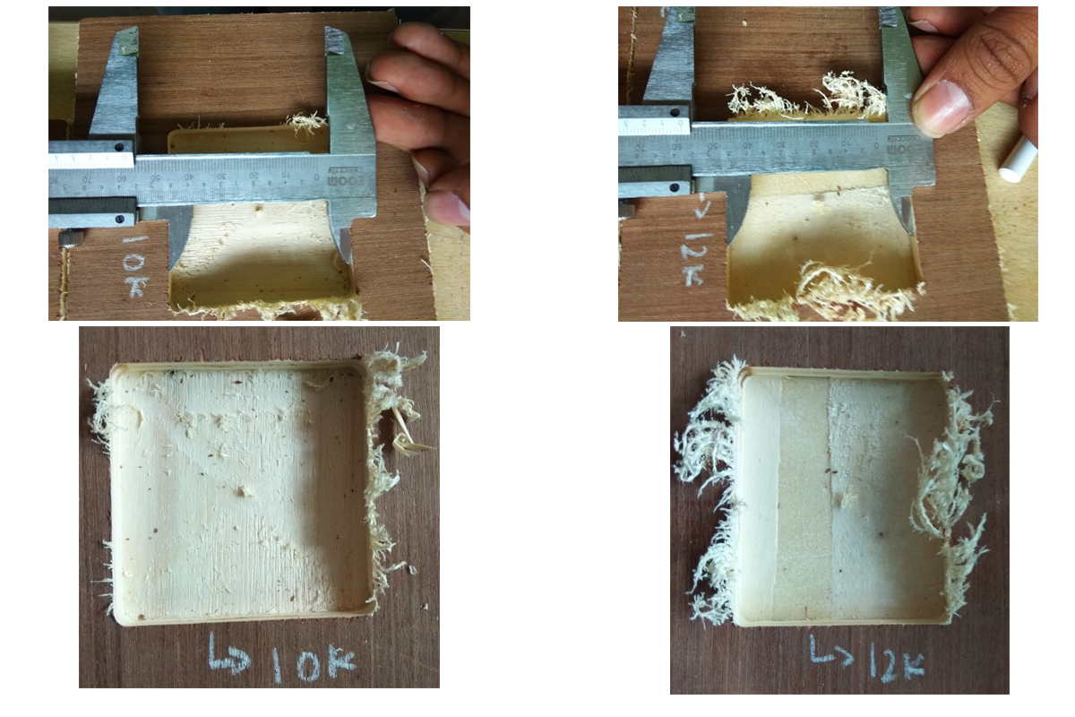
Spindle speed test: For testing the spindle speed we take two pocket design at 12000 rpm/10000 rpm and for outline cutting we take four different speed like 12K/11K/10K/9K we see some difference here.
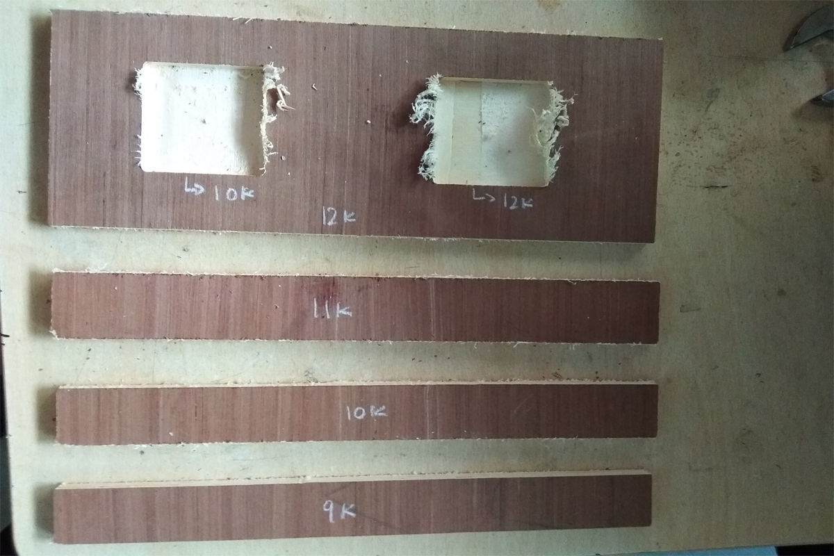
Pocket Cutting: After cutting we saw that their is no difference for pocket cutting in different spindle speed. But the it has difference in smoothness. where as the 12K is rough than the 10K spindle speed.
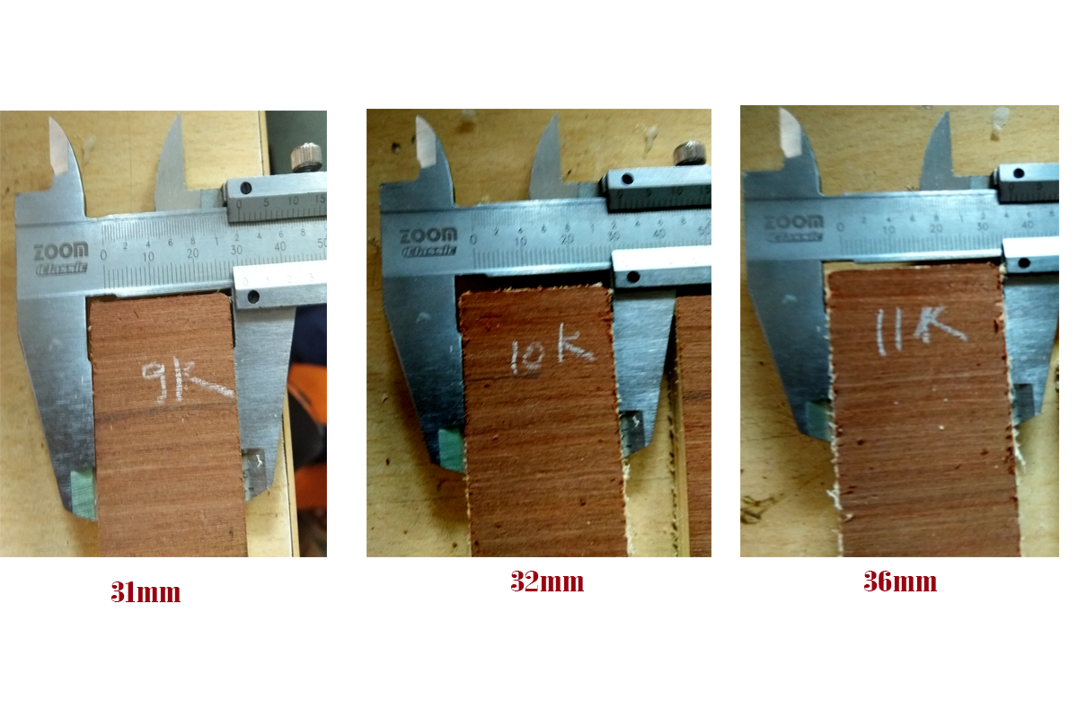
Spindle Speed 12K/11K/10K/9K rpm Cutting: Here we saw some difference in cutting of the different spindle speed. where 11K is less cut than the 10K and 9K.
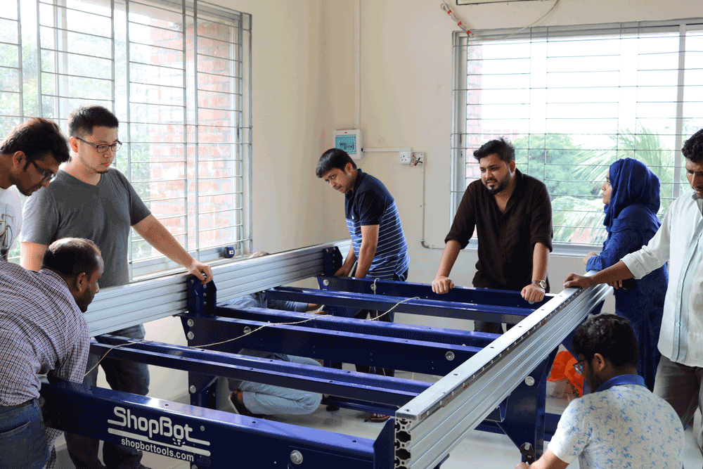
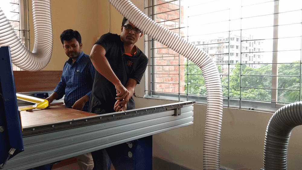
After came back from Vigyan Ashram in 22 MAY last month and then 25th MAY we were install our shopbot PRS Alpha in FABLAB SAU. For installation and software training were done by JC Chang from FABLAB TAIPEI, TAIWEIN.
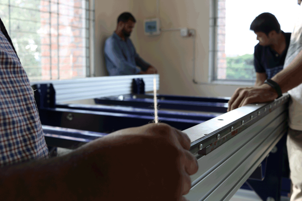
Measuring the alignment of the shopbot bed and fix the proper align. This is essential part for fix of the gantry on the rail of stand.
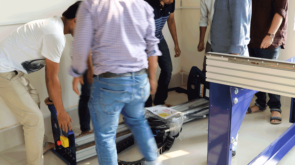
After thanks tighten the screw to fix the stand and rail for accurate gantry setup
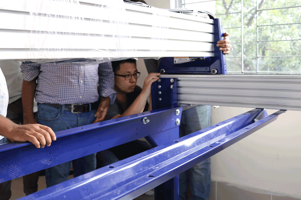
Gantry setup, lifting it and upon in the rails
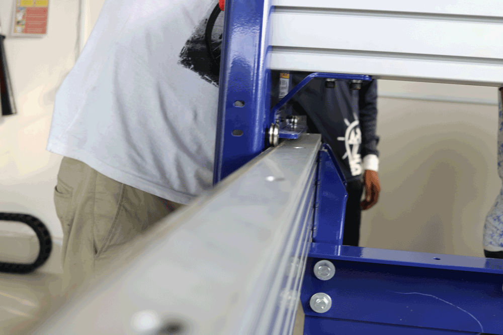
Gantry wheel setup and align it to the rails
Checking the rails and gantry again and be sure it to set upon the
After surfacing now we setup the cutting board
Fix up the endmill for test cut
Setting the Z zero by using auto zero panel
Cutting is going on:
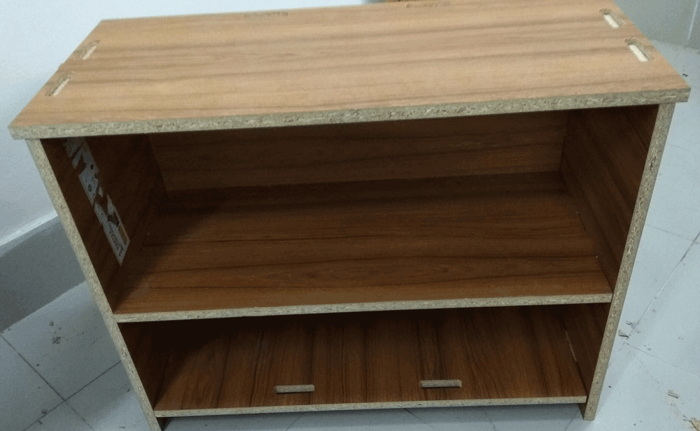
After assembly these cutting part
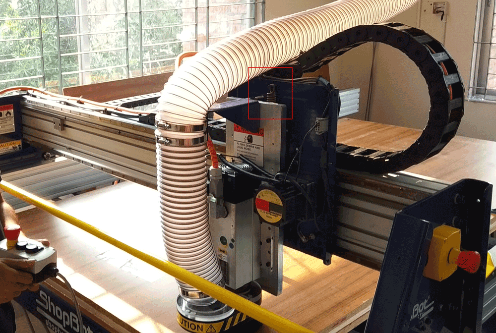
During installation of the shopbot, we notice no thing that is one of the spring are missing in gantry which is holding the spindle in the z axis and move it as gcode command during cutting. But we try it attached a local spring here, we already contact with shopbot they already did their shipment and as soon as we get it the I start to cut design with dogbone again.