
Embedded Programming
- 1. DataSheet reading about ATtiny44A
- 2. Programming Hello Board using FabISP in different programming environment
- 3. Group Assignment: Program the board by other Architecture (optional)
Embedded Programming
During the Electronics Design week, I modified Neil's hello.ftdi.44 board by adding a pushbutton switch and an led. Since this board is based on the ATtiny44 micro-controller, I started with the Atmel datasheet for this device.
The Datasheet is available in the Atmel website. There are many versions of the document, it's in 286 pages. There is also a 26-page summary datasheet Check Here. The summary document contains the main features of the MCU, the pinout diagram, architecture overview, register summary, assembly instruction set and packaging information, but doesn't describe the micro-controller features in detail. To really understand the micro-controller, you would need to read the full datasheet.
Feature: Check the Images in below.
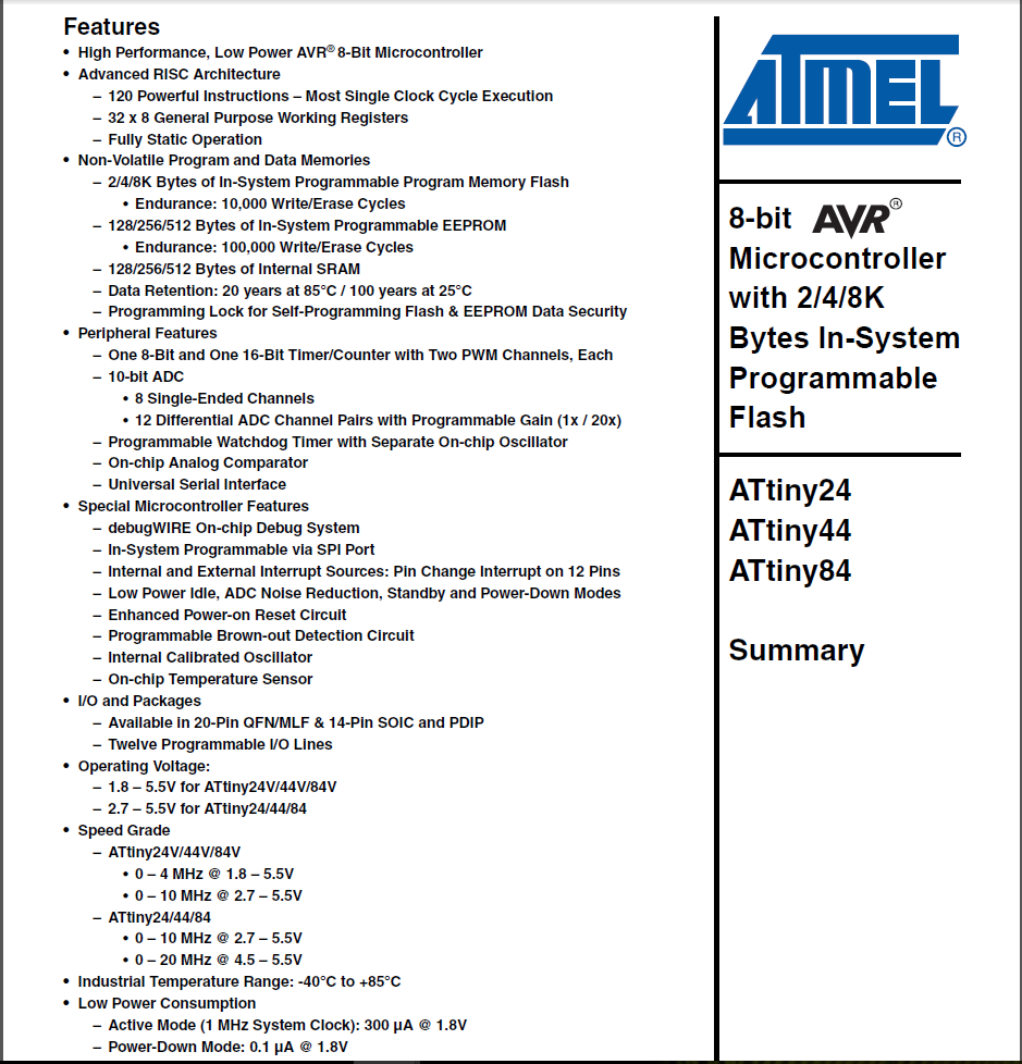
For learning about micro-controller the datasheet information is better source. we know that there are 3 versions of the MCU - the ATtiny24A, ATtiny44A and ATtiny84A, all with the same architecture and feature set of different amounts of flash memory. The memory retain 20 years at 85 degree C and 100 years at 25 degree C. In datasheet there some peripherals available on this IC, such as timer/counters, pwm channels, ADCs, analog comparators and serial interfaces. We know that the IC is available in different packaging, ranging from 14-pin SOIC or PDIP to 20-pin VQFN. There are 12 programmable I/O lines on the MCU and it can operate with supply voltages from 1.8 - 5.5V, with operation at higher frequencies requiring higher supply voltages.It is only rated for temperatures between -40 to 85 degC.
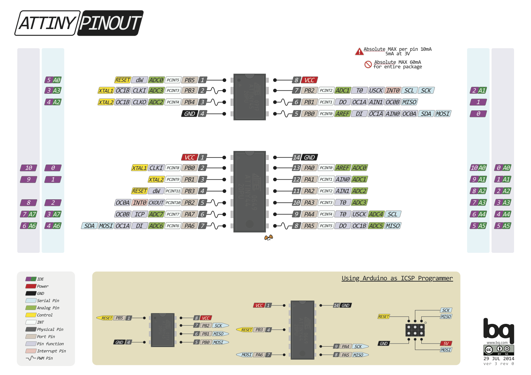
Pin Out of Attiny44A In section 1, the pin out/pin configuration are clearly explain. I downloaded a images from Pinterest about pinout where it explain the I/O pinout of the IC and also mansion the pin outline for Arduino ICSP here.
There are three hardware register memory locations: DDRxn, PORTxn and PINxn Lower case x is the number letter for the port and n represents the number. DDRx pins set the direction of the pin. If logic one is written on DDRxn, Pxn is configured as an output pin. Conversely, if DDRxn is written logic 0, Pxn is configured as input. One particularity, is that if the data direction register is configured for input and PORTxn is written logic one, an internal pull-up resistor in PORTxn is activated. When DDRx bits are set to logic one (as output), the PORTx register will control if that pin is set to low or high.
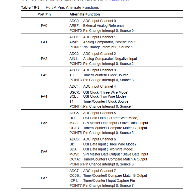
Alternate Function of PIN :In section 10.2.1 table has illustrated the PORT(A0:A7) detail.
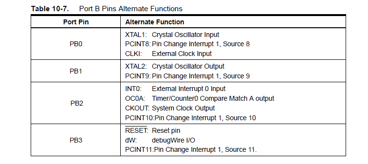
Alternate Function of PIN :In section 10.2.2 table has illustrated the PORT(B0:B3) detail.
Clock Speed Distribution :The Clock System section of the datasheet tells us that the ATtiny44A can derive its system clock from different sources: internal RC oscillator, low-frequency crystal oscillator, crystal oscillator or external clock source. The clock signal passes through a clock multiplexer circuit and from there, to a pre-scaler unit. There is also a watchdog oscillator, which is used to reset the MCU if the watchdog timer is not reset with the WDR instruction within a prescribed time interval. The watchdog timer is initially disabled, but can be enabled by writing a logic 1 to the WDE bit in the WDTCSR (Watchdog Timer Control and Status Register).
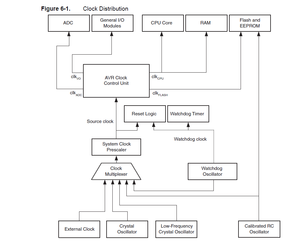
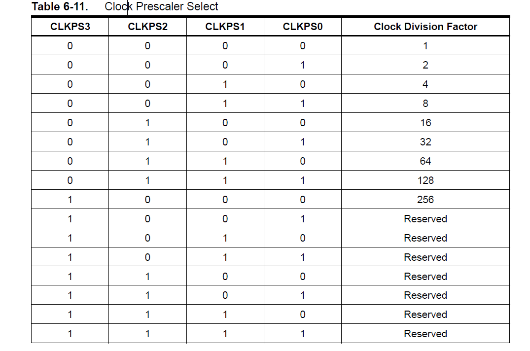
The clock source is selected by means of the CKSEL[3:0] bits and the Start-up Times with the SUT[1:0] bits. The prescaler value is configured via the Clock Prescaler Select Bits (CLKPS[3:0]). For example, to configure the MCU to use the 8 MHz internal RC oscillator, with a prescaler value of 8 (i.e. divide by 8, for a 1 MHz clock), start-up clock 14CK + 64 ms, the settings would be:
There are a lot more settings and configuration examples in the ATtiny44A datasheet, so what ever to be used as a reference when you need to access specific features of the IC.
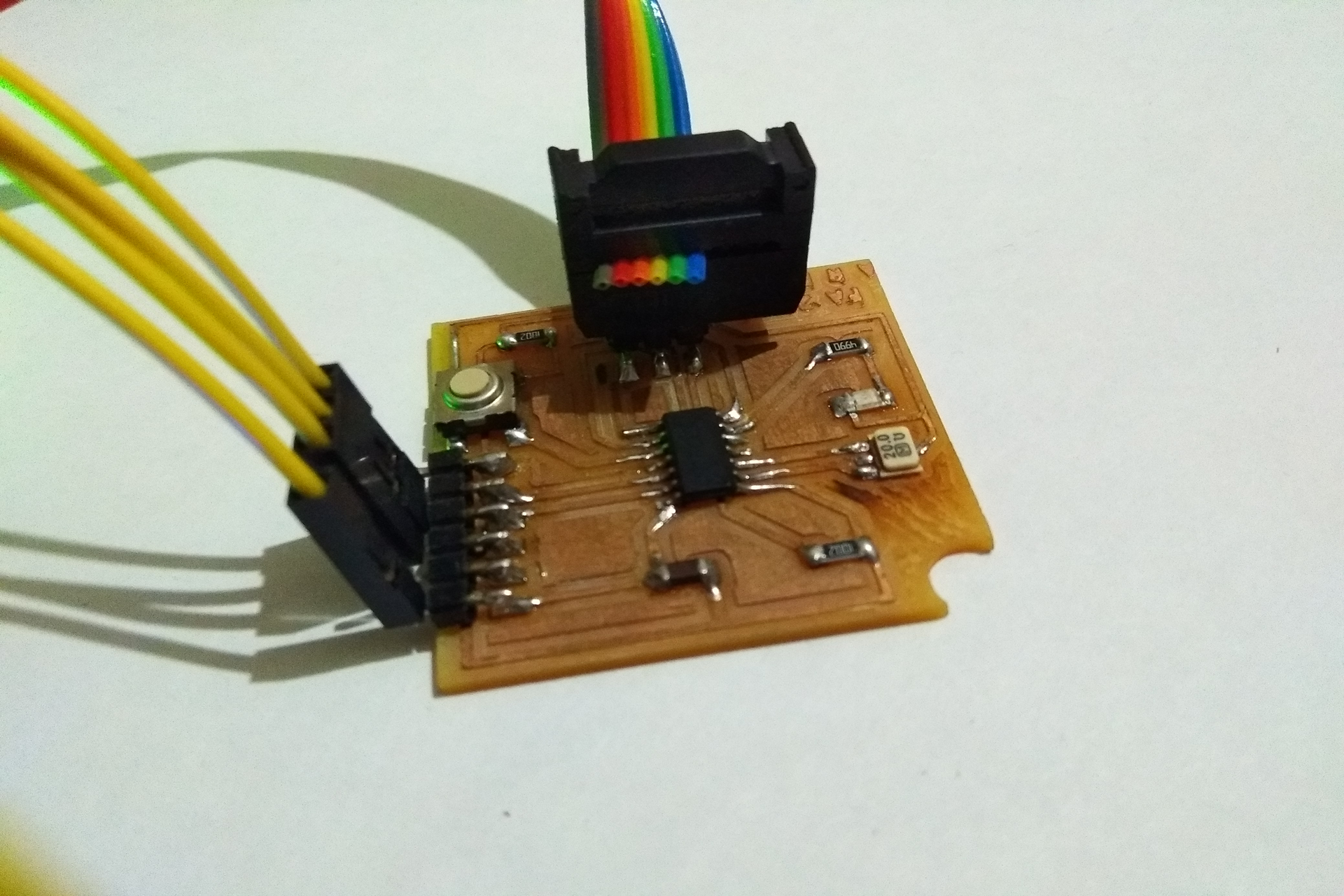
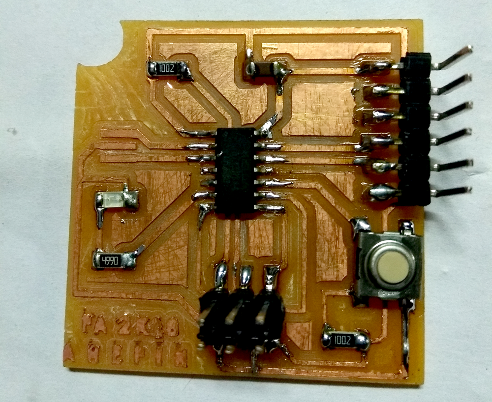
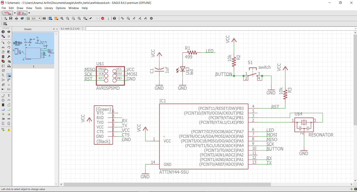
Hello Board In electronic design, i make a board by editing hello.ftdi.44.echo board and add two extra component, one button and one led light.
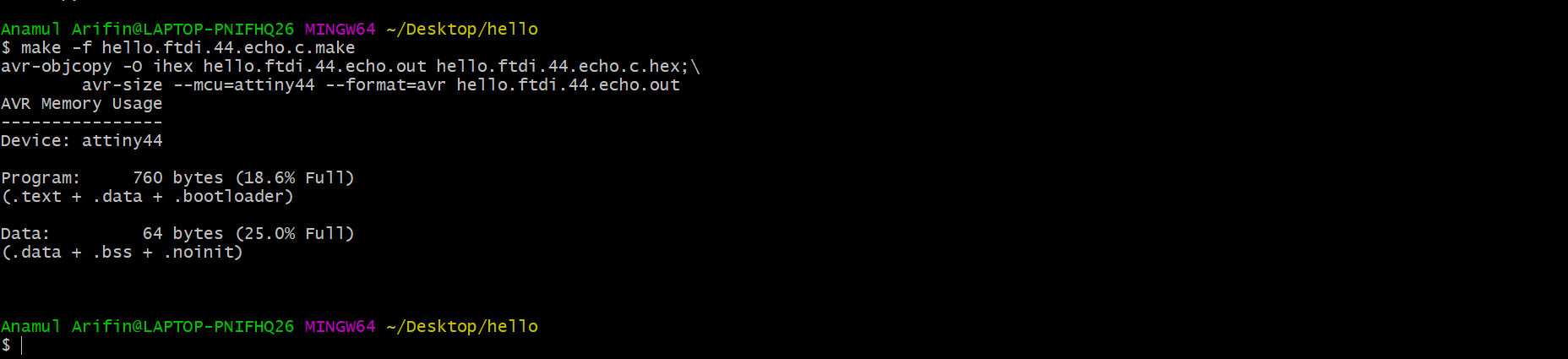
My first step to make sure that the toolchain software are available for programming avrdude and avr-gcc. Then I downloaded the example source code C and make file and then I follow this Tutorial to compile the code, set the fuses and program the board.
make -f hello.ftdi.44.echo.c.make
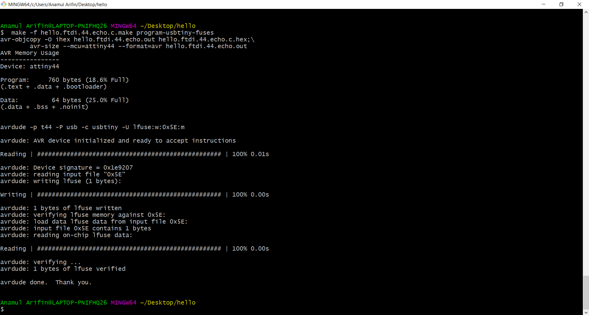
make -f hello.ftdi.44.echo.c.make program-usbtiny-fuses
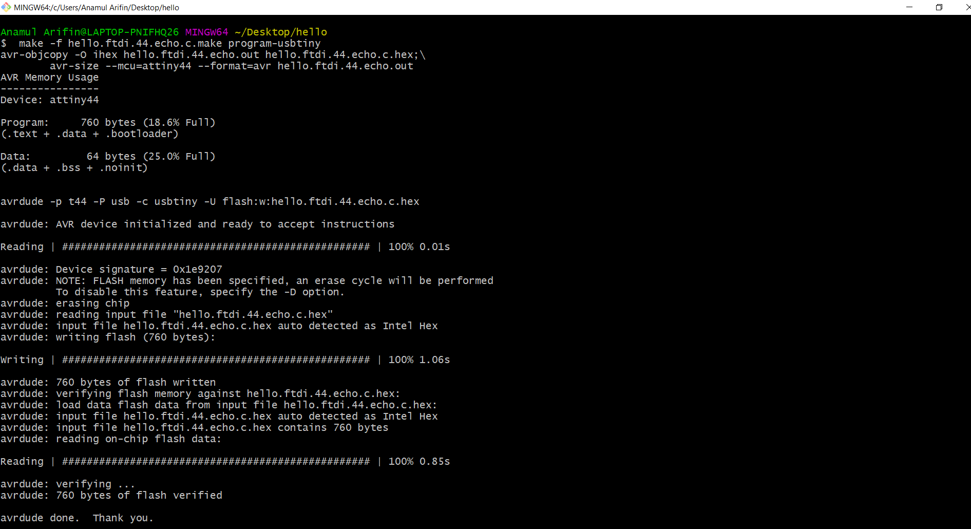
make -f hello.ftdi.44.echo.c.make program-usbtiny
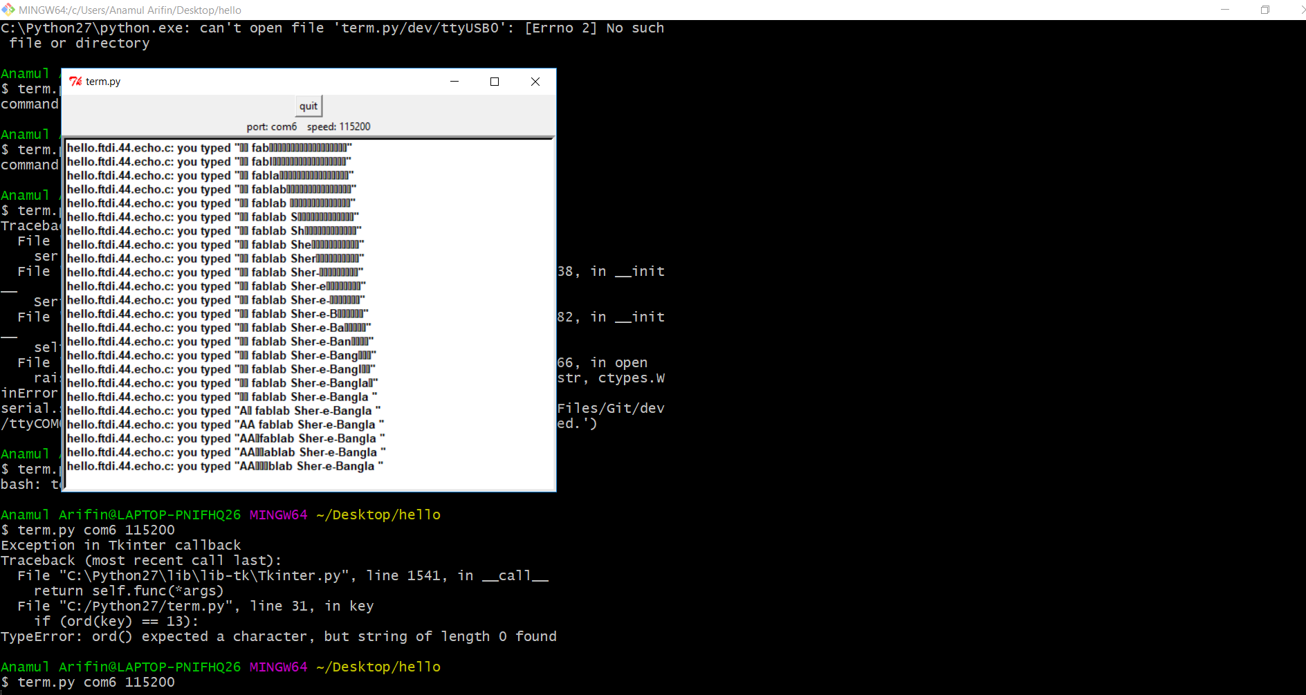
I spent a few hours trying to get term.py installed with pip, so I could test if the board was working as expected. In the end, I opened up the Arduino IDE, selected term.py com6 115200 as the serial port and opened up the Serial Monitor with a 115200 baudrate.
First i checked my hello board schematic design where was i connected the led, pin number is PA7.
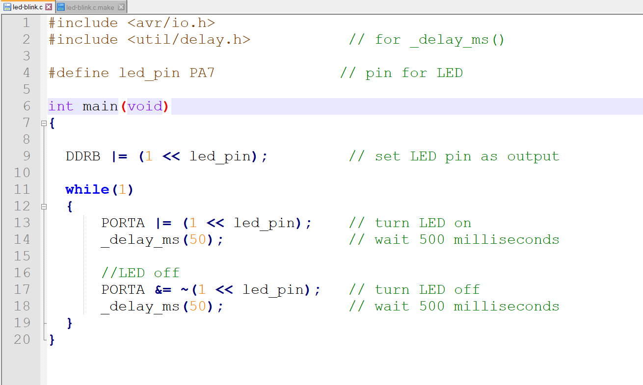
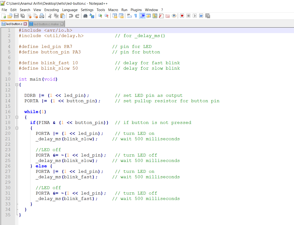
For programming I looked at examples from Fab Academy students from previous years including Massimo Menichinelli This post by Mayank on maxembedded.com was also helpful. Drawing from these and referencing stack overflow occasionally, I wrote the following code to turn on the LED:
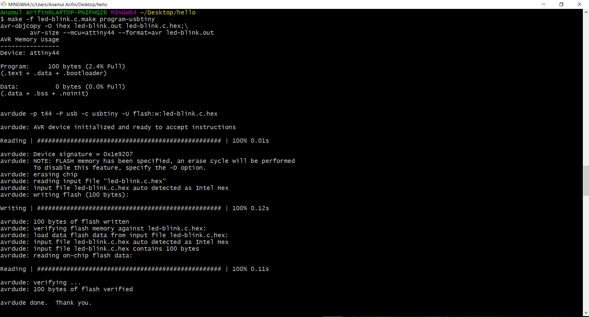
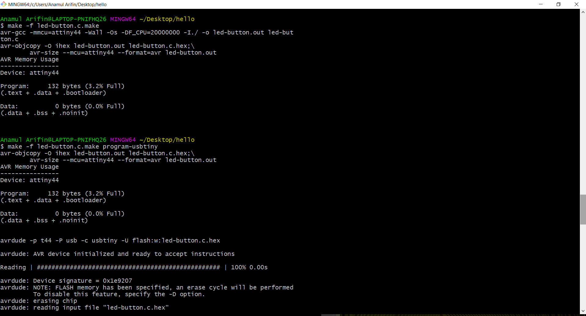
Then command in git bash as following code:
Here also I doing same thing, this code file i collected from the previous student assignment. Image and video in below:
C File: Button-led blink
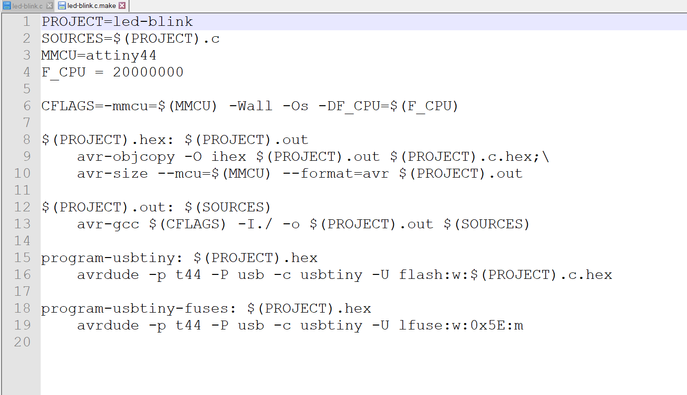
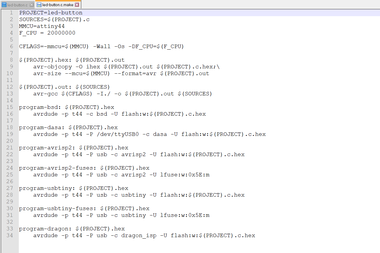
Make File: Button-led blink
Then command in git bash as following code:
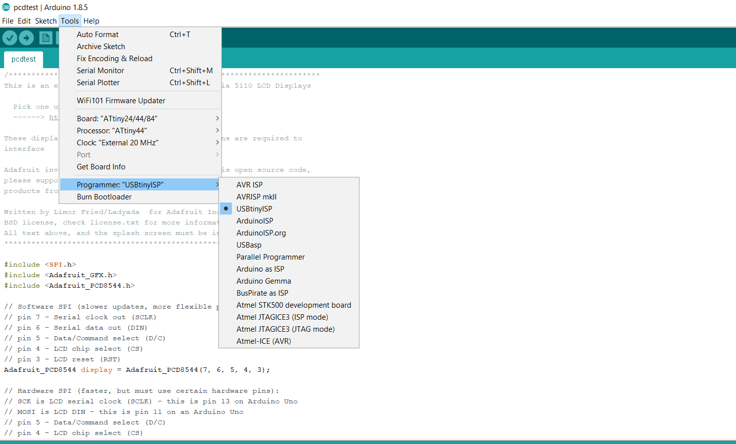
First I open Arduino 1.8.5 and I was connected ISP and my board. First I select some option like Board, processor, Clock, COM port, programmer, where i select as USBtinyISP, The settings for clock and programmer, Image below:
1. First I selected the board as ATtiny24/44/84 for the programming on the chip
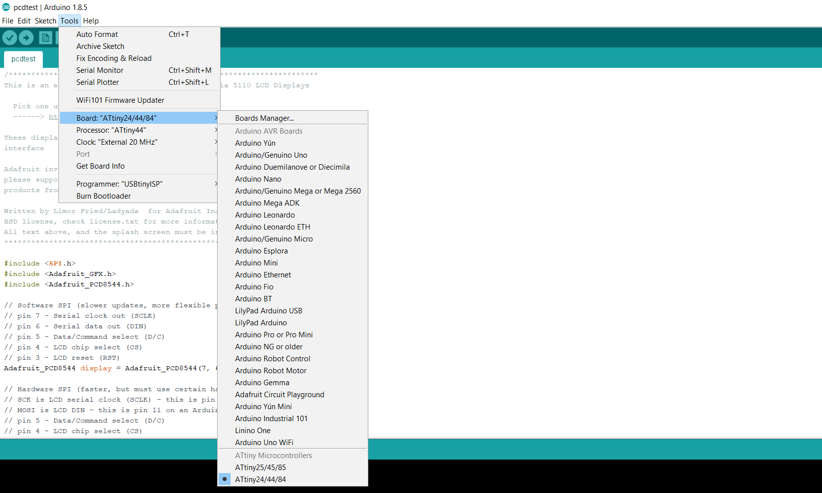
2. The select the processor type in the chip, which is ATtiny44
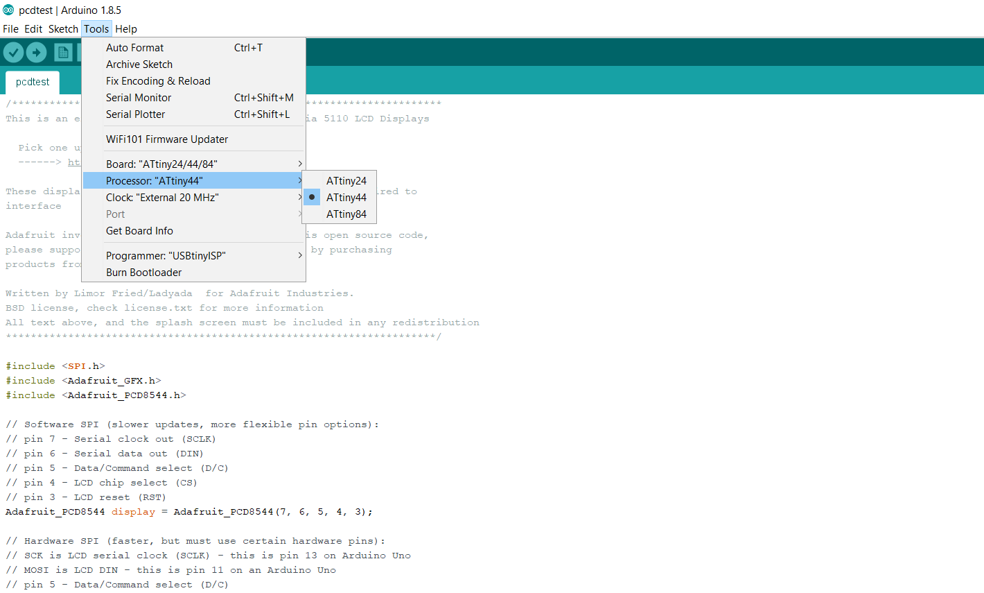
3. Here I select the clock speed in the board, that is 20MHz.
4. USBtinyISP, selected as a programmer here
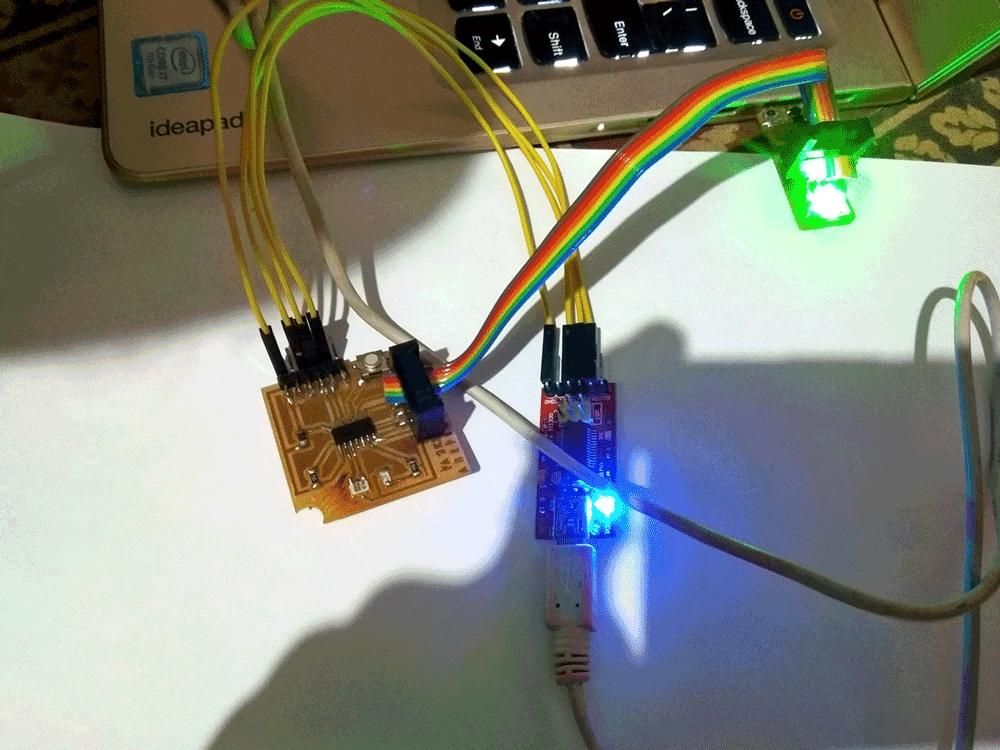
5. Here I Connect the Hello board with PC vai FTDI cable and also connect with FABISP with ISP header PIN, FABISP directly connect with USB with PC.
The code which I used from the example of Arduino, its given below:
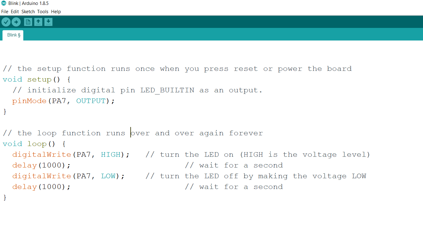
Here Uploading the code in the chip of hello board
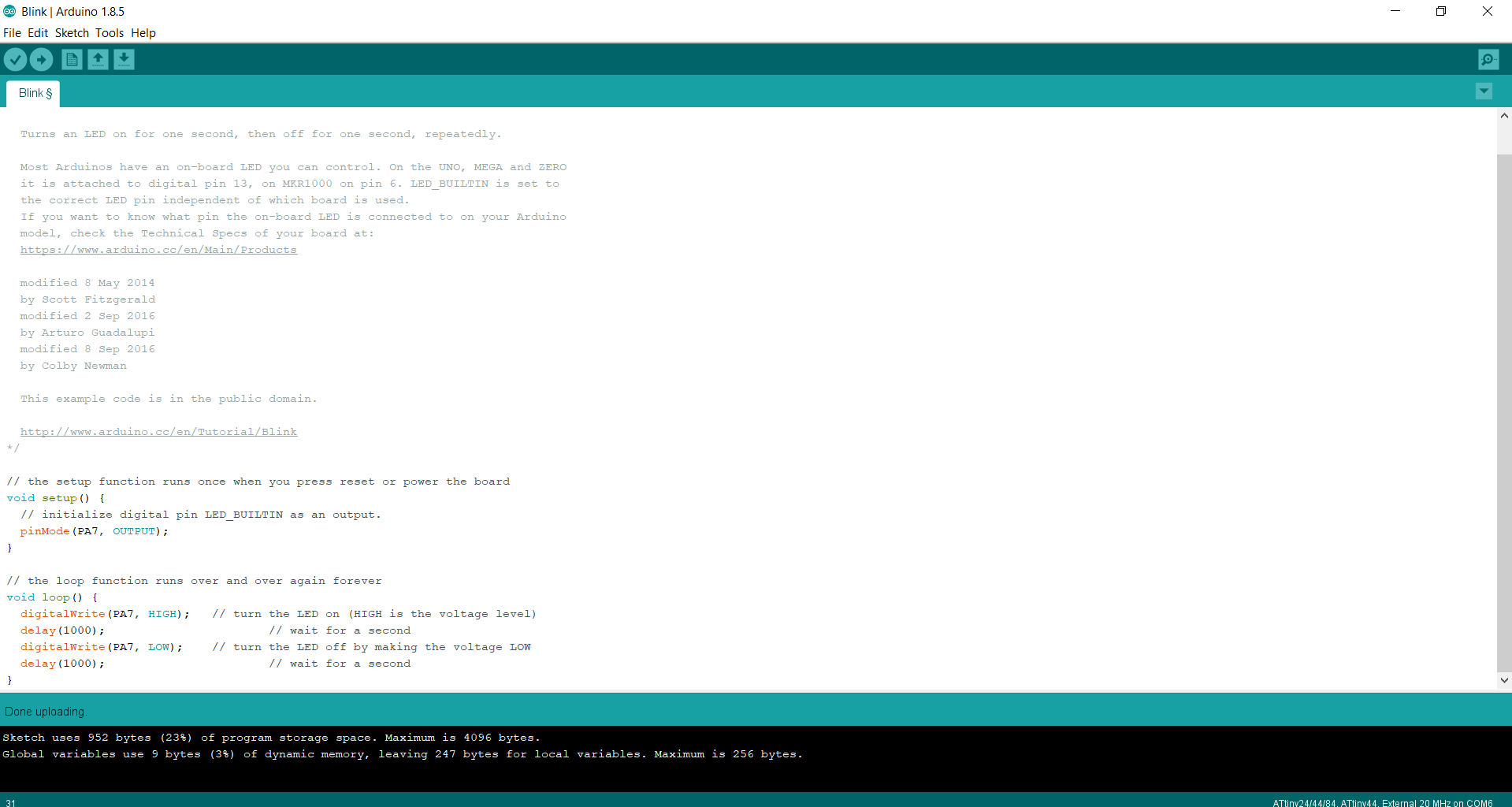
Blink Test:
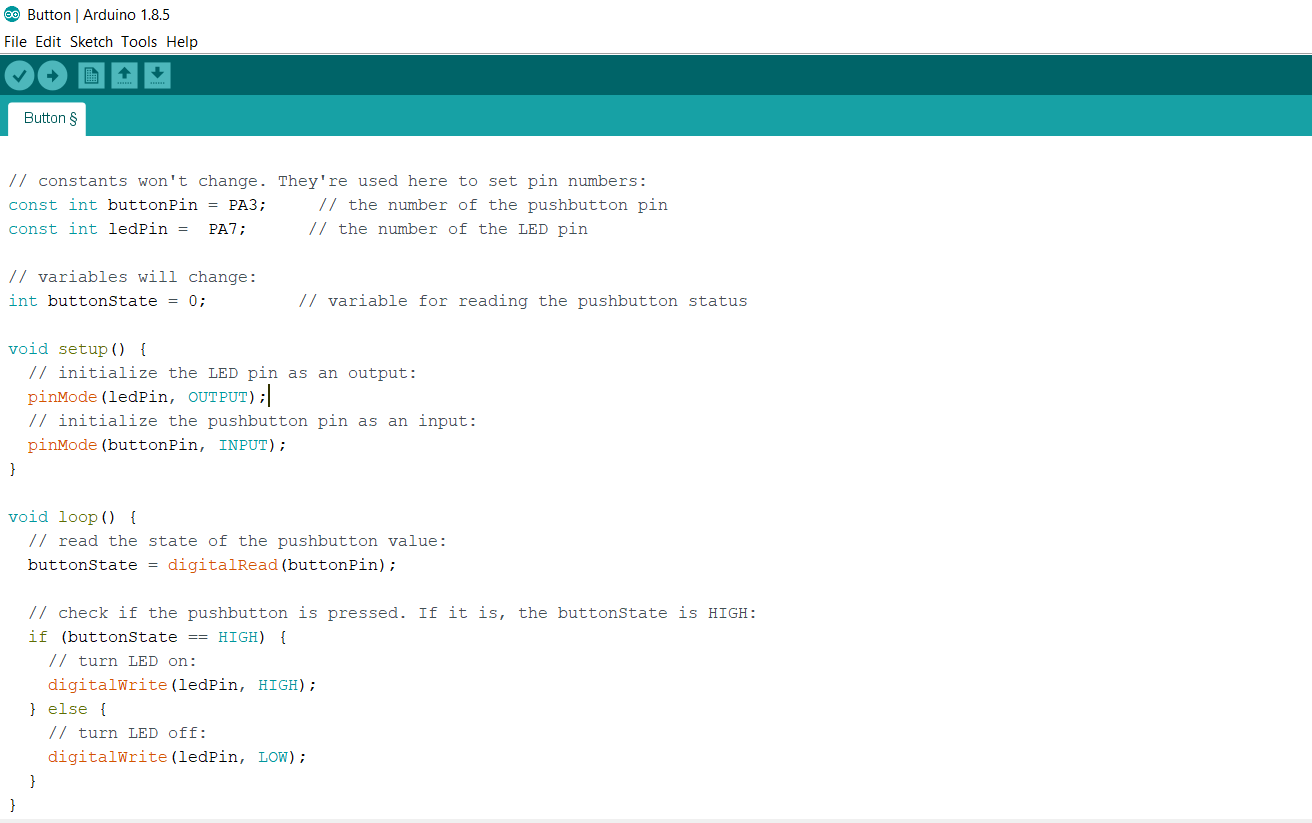
I follow the same process as i was followed in LED Blink test, here in code I changed the ledPin=PA7, buttonPin=PA3 as by board diagram and uploaded the code into the micro-controller.
Uploading the code into microcontroller
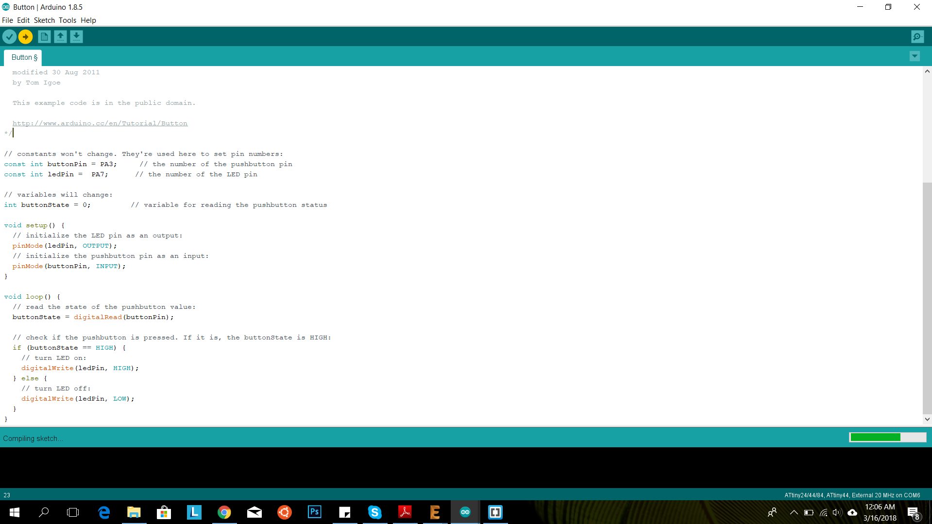
Button Test:
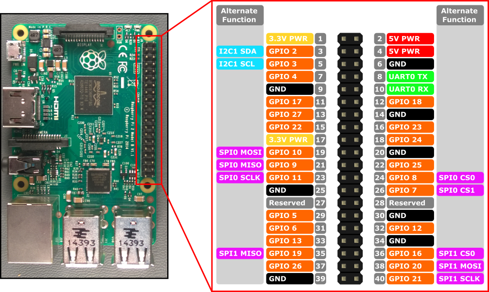
For this week we had decided to explore Raspberry pi, it's architecture, configuration and coding it through python
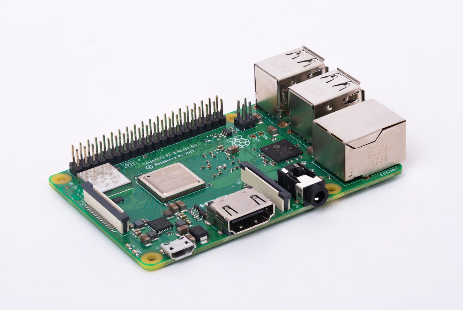
The configuration of the board that we used is listed as follows:
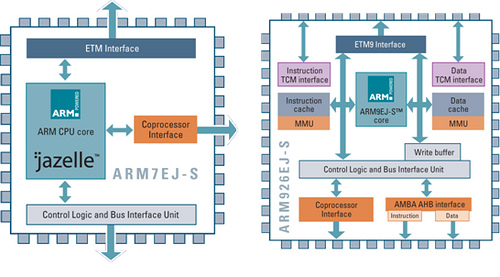
There are few special features that can be listed as follows:
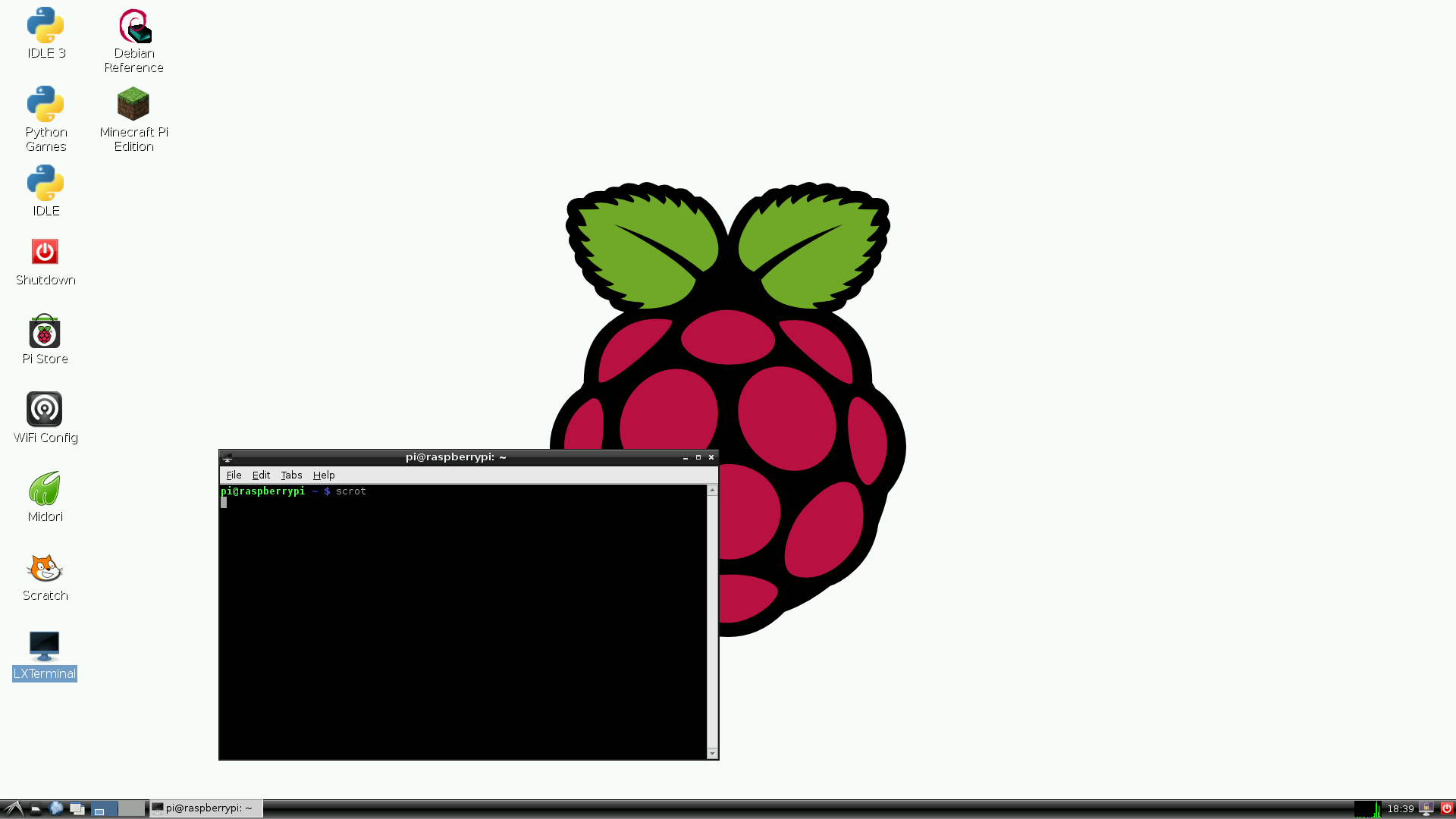
For this we had connected the raspberry pi b+ with keyboards and powered it up, to boot through it. The OS that we had installed was Raspbian , having a pretty simple user interface
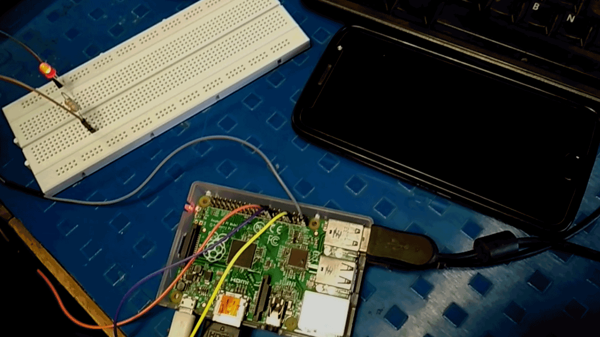
Along with that we had connected an LED to the the GPIO pin of the pi board using a connection on the bread board. Hence our entire circuit appeared to be like this..
After this we wrote a test program for blinking the LED in the local text editor in raspbian. The code was pretty easy, {Written in python}, explained below
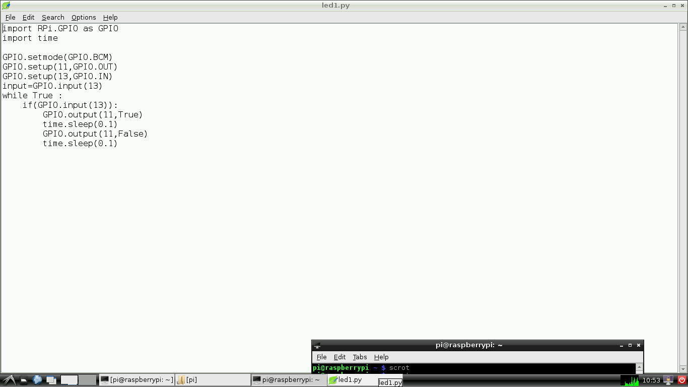
During the compilation the compilation the major challenge was to notice the pin that we had plugged the LED onto , and then write the pin number in the code. This was not quite that difficult but rather confusing because the pins can be assigned. Finally we assigned the numbers in the following order seen here.
Finally we tried to run the program and got the following output
To conclude when I compared the languages of programming I found that python is comparatively very easy to understand and write, having a prety easy syntax.
Also the method of transferring and executing the program is pretty easy as compared to other methods that I programmed my hello world board.
Also there is an advantage of choosing the program, about what to run, since Raspberry pi has the ability to store and execute multiple programs, where as the other board overwrite the initial program when other one is loaded.