Week 11 assignments:
Output devices:
From Fab Academy 2018 assignments
1. measure the power consumption of an output device (GROUP PROJECT).
2. Add an output device to a microcontroller board you've designed and program it to do something(INDIVIDUAL PROJECT)
Have:
Described your design and fabrication process using words/images/screenshots.
Explained the programming process/es you used and how the microcontroller datasheet helped you.
Outlined problems and how you fixed them
Included original design files and code
Electronic Circuit
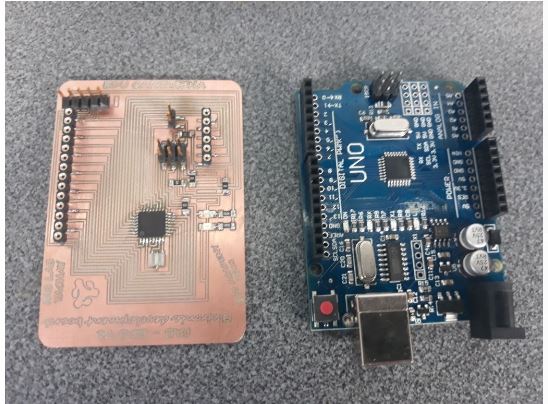
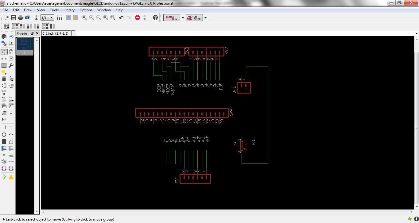
For this week I wanted to try different output devices, so I decided to design and manufacture an electronic development board similar to an arduino ONE board.
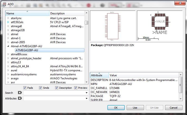
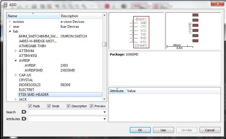
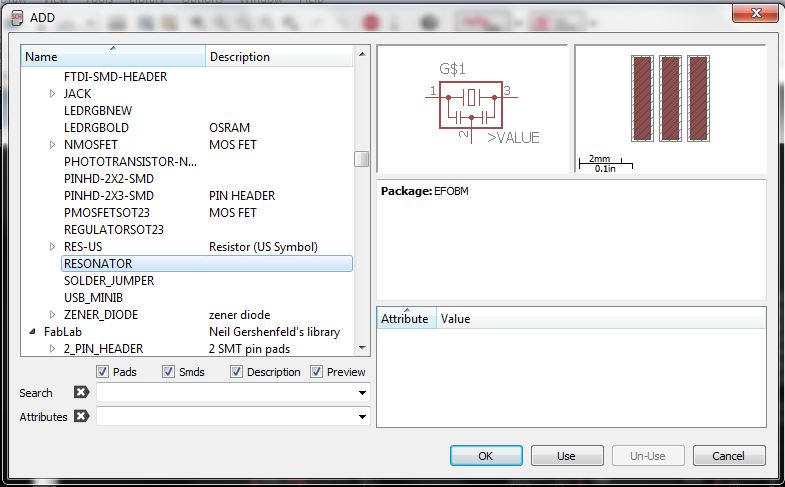
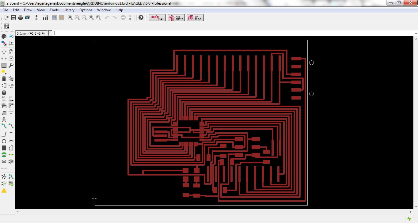
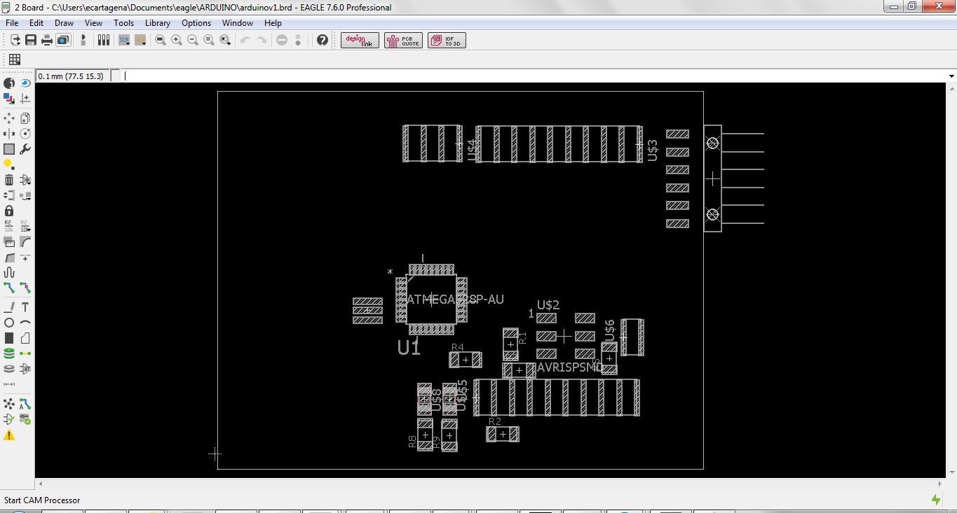
For the design of the electronic development board use the EAGLE software of Autodesk
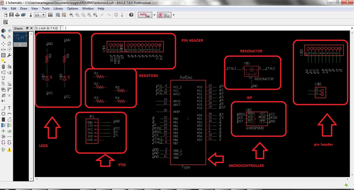
Components used
- 1 Atmega328P AU microcontroller
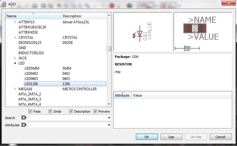
- 2 LEDs
- 5 resistors 0 ohms
- 2 resistors 499 ohms
- 1 resonator 20Mhz
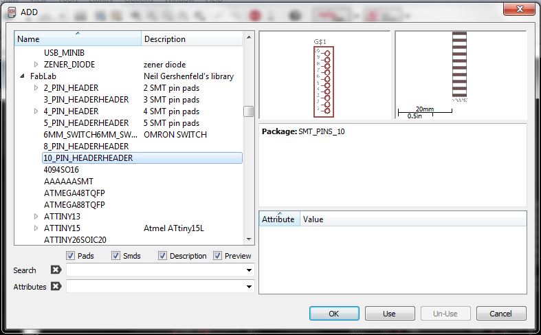
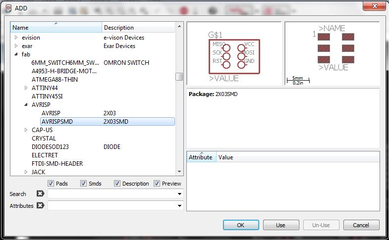
- 1 pin header 3x2 ISP
- 1 pin header to inputs and outputs
- 1 pin header to ftdi
Schematic Design
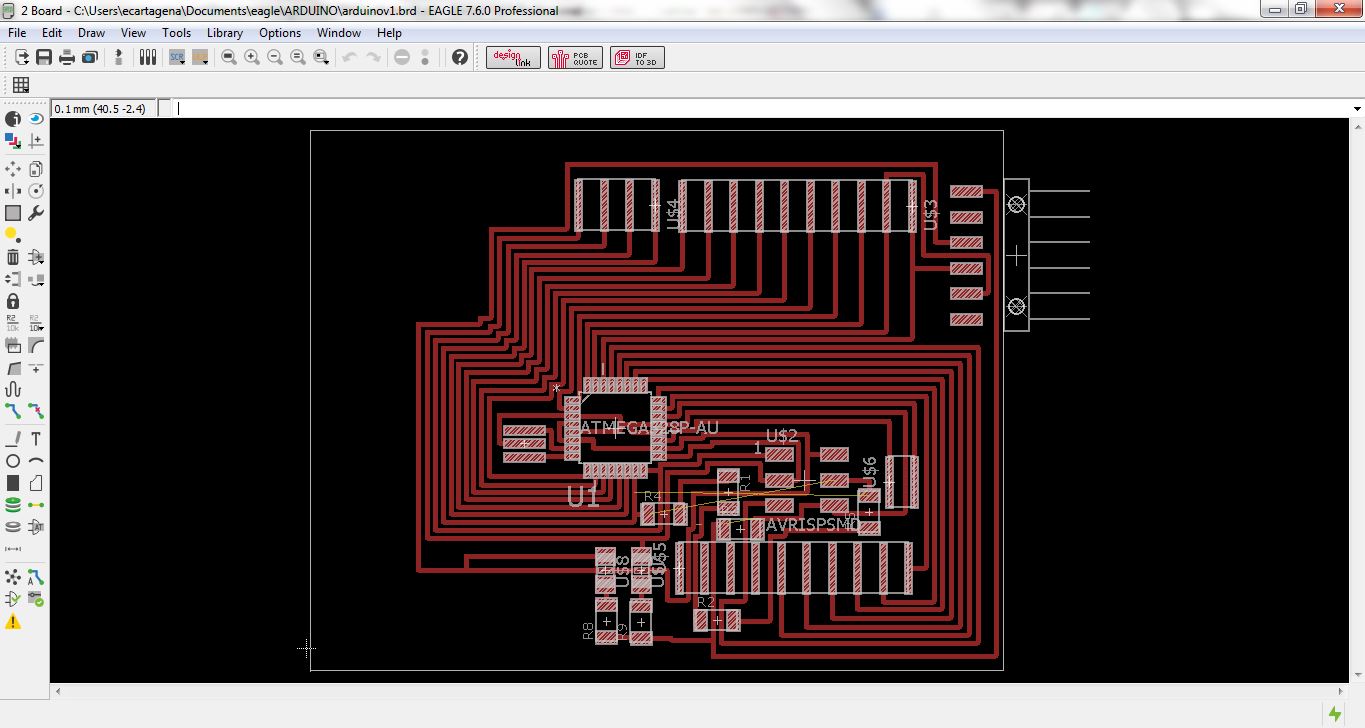
Board Design
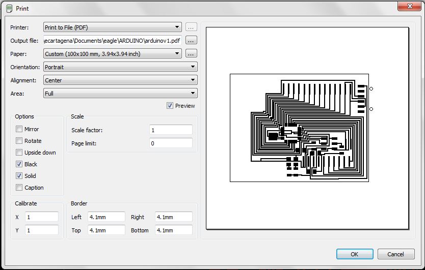
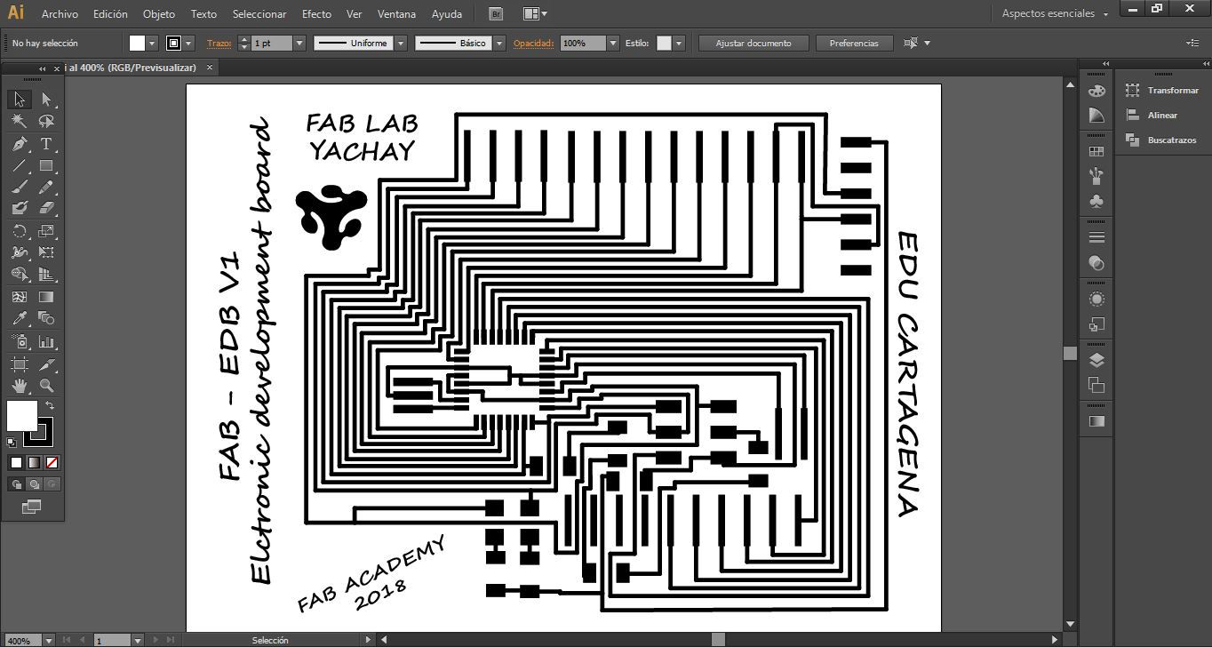
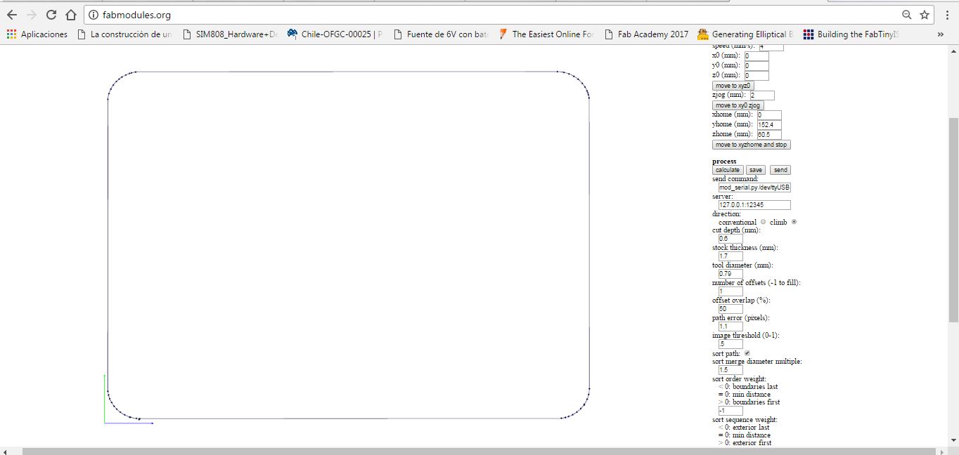
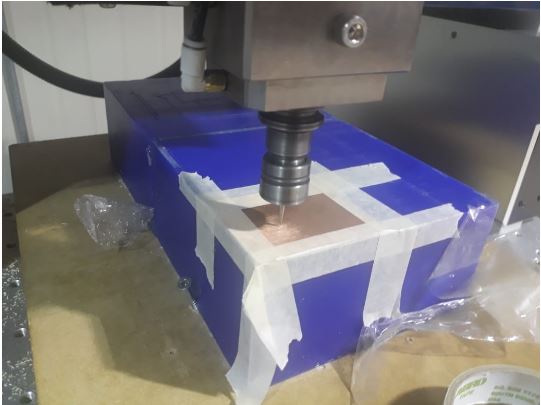
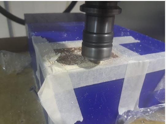
Generation of milling and cutting files
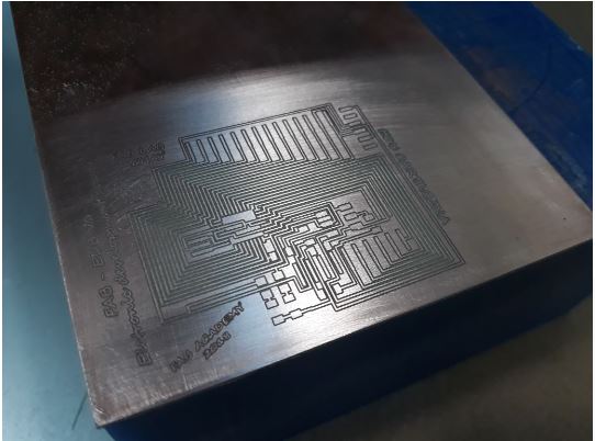
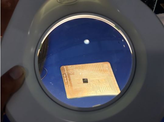
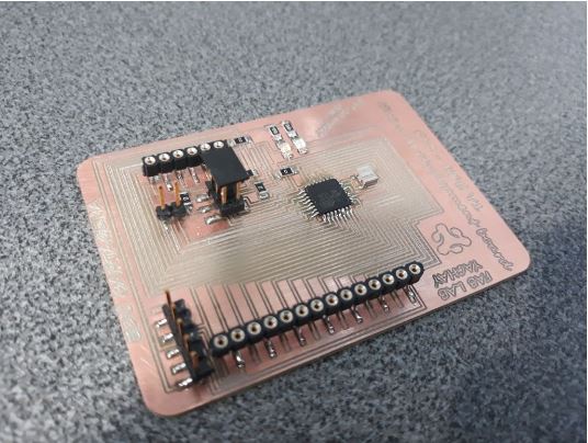
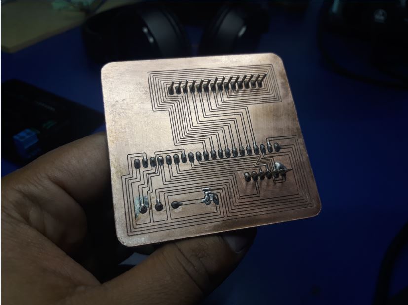
Manufacturing and implementation
Test of electronic development board
To test the board, load the arduino blink program
OUTPUT DEVICE
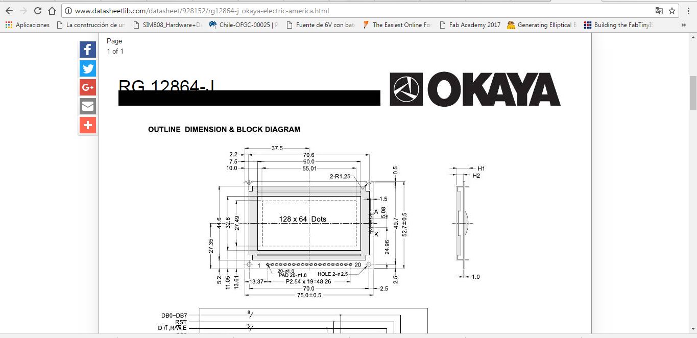
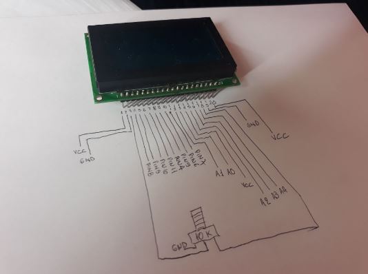
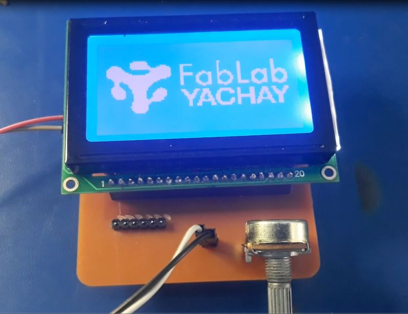
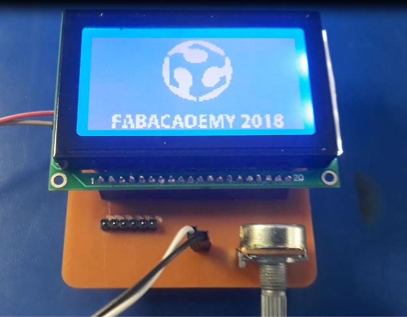
The assignment for this week is add an output device to a microcontroller board you've designed and program it to do something, in this case I am going to add a graphic lcd screen the 128 x 64 pixels to visualize differents images.
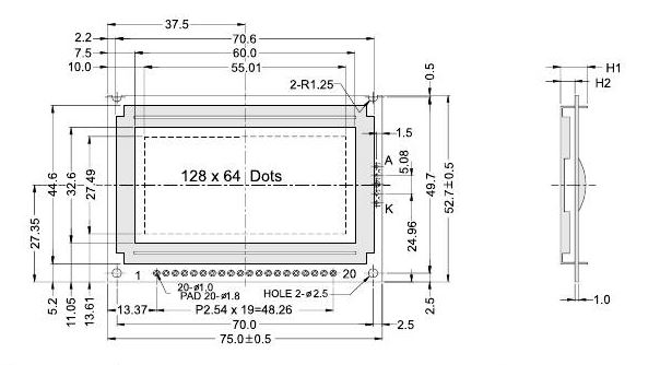
Datasheet GLCD
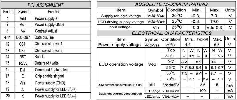
Connection
Programming
Implement and interpret programming protocols
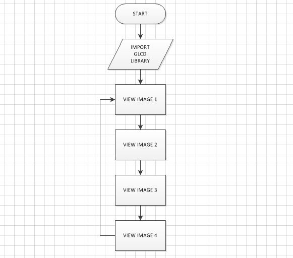
- To facilitate the programming it is important to make a flow diagram that allows to interpret the operation of the program
- Identify the functionality and correct connection of the pins of the output device to program them properly.
- If you use serial communication, identify the data transmission speed, this must be the same in the transmitter and in the receiver.
- Identifies the protocol that uses the output device through the datasheet to program it correctly.
- Use the appropriate voltages and currents.
- Write your program as simple and direct as possible
- Within the defined functions, it establishes a spacing or indentation, that highlights the functional structure of the application and facilitates the reading to the programmer to whom it corresponds to analyze the code.
- Putting a space after each comma (,) facilitates the readability of the code.
- Do not use variables whose name does not have any descriptive meaning, a variable with significant names allows the reader to understand the context of the code and allows to decrease the amount of associated documentation, since with a readable code and significant names, the code is self-documented. For example, a variable called quantity_requires, has more meaning than a variable called c.
- Comment when it is fair and necessary, use the comments within the functions to describe the variables (only when their usefulness is potentially doubtful) and when there are blocks of code that are difficult to understand at first glance; the excess of comments renders the code illegible.
- Never forget to initialize counters and adders.
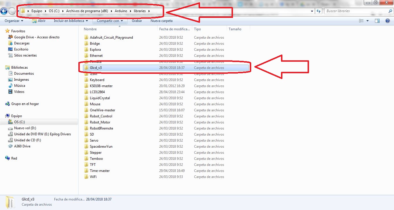
To program use the integrated development environment of Arduino, it is necessary to download the library GLCD.h
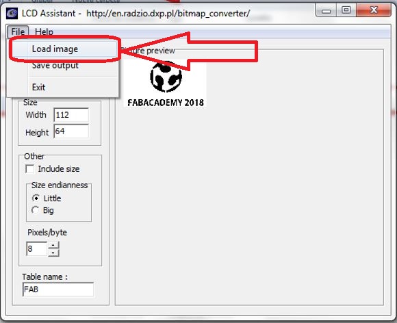
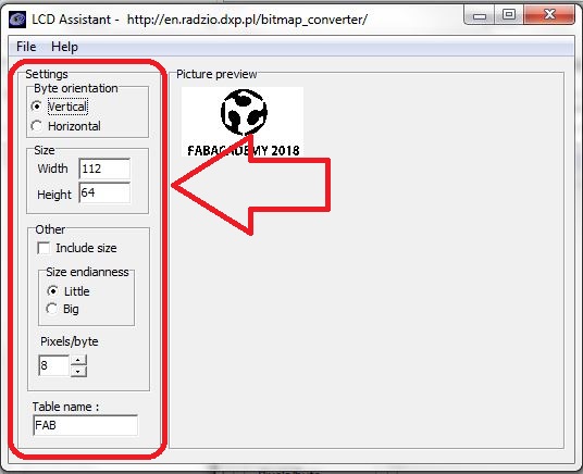
For viewing images on the GLCD screen it is also necessary to download the LCDAssistant program
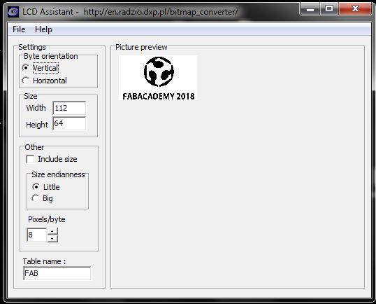
LCD Assistant allows us to convert an image into hexadecimal code
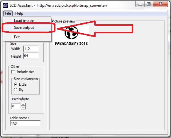
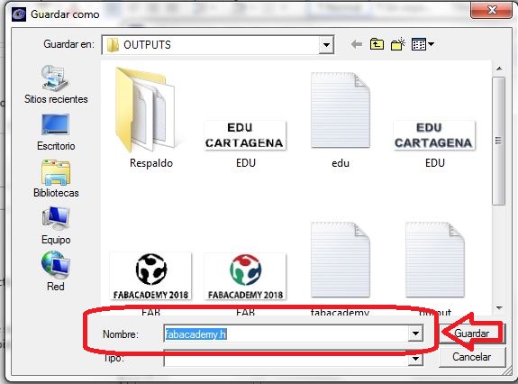
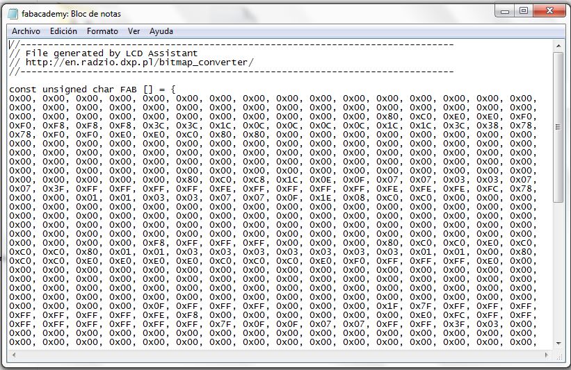
Now with the code we must generate two files with the extension .h, for which you can use the SublimeText software.
File1: ArduinoIcon2.h
#ifndef ArduinoIcon2_H
#define ArduinoIcon2_H

#define ArduinoIcon2 ArduinoIcon64x642
#include "bitmaps/ArduinoIcon64x642.h"

#endif
File2: ArduinoIcon64x642.h
#include
#include

#ifndef ArduinoIcon64x642_H
#define ArduinoIcon64x642_H

const static uint8_t ArduinoIcon64x642[] PROGMEM = {
  120, // width
  43, // height

0x00, 0x00, 0x00, 0x00, 0x80, 0xC0, 0xC0, 0xC0, 0xC0, 0x80, 0x80, 0x00, 0x00, 0x00, 0x00, 0x00,
0x00, 0xF0, 0xF0, 0xF8, 0xF8, 0xF8, 0xF8, 0xF8, 0xF8, 0xF8, 0xF8, 0xF0, 0xC0, 0x80, 0x00, 0x00,
0x00, 0x00, 0x80, 0x80, 0xC0, 0xC0, 0xC0, 0xC0, 0x80, 0x80, 0x00, 0x00, 0x00, 0x00, 0x00, 0x00,
0x00, 0xC0, 0xC0, 0x40, 0x40, 0x40, 0x40, 0x40, 0x40, 0x00, 0x00, 0x00, 0x00, 0x00, 0x00, 0x00,
0x00, 0x00, 0x00, 0x00, 0x00, 0x00, 0x00, 0x00, 0x00, 0xF0, 0x10, 0x00, 0x00, 0x00, 0x00, 0x00,
0x00, 0x00, 0x00, 0x00, 0x00, 0x00, 0xE0, 0xE0, 0x00, 0x00, 0x00, 0x00, 0x00, 0x00, 0x00, 0x00,
0x00, 0x00, 0x00, 0x00, 0x00, 0x00, 0x00, 0x00, 0x00, 0x00, 0x00, 0x00, 0xF0, 0xF0, 0x00, 0x00,
0x00, 0x00, 0x00, 0x00, 0x00, 0x00, 0x00, 0x00, 0x00, 0x00, 0x3E, 0x7F, 0x7F, 0xFF, 0xFF, 0xFF,
0xFF, 0xFF, 0xFF, 0xFF, 0xFE, 0xFC, 0xF8, 0xF8, 0xF0, 0xF0, 0xE1, 0xE1, 0xE1, 0xE1, 0xE1, 0xE1,
0xE1, 0xE1, 0xE1, 0xF1, 0xF1, 0xFB, 0xFF, 0xFF, 0xFF, 0xFF, 0xFF, 0xFF, 0xFF, 0xFF, 0xFF, 0xFF,
0x7F, 0x7F, 0x3F, 0x00, 0x00, 0x00, 0x00, 0x00, 0x00, 0xFF, 0xFF, 0x30, 0x30, 0x30, 0x30, 0x30,
0x30, 0x00, 0x00, 0xC0, 0xE0, 0x70, 0x30, 0x18, 0x18, 0x10, 0x20, 0xF0, 0xF0, 0x00, 0x00, 0x00,
0x00, 0xFF, 0x60, 0x30, 0x10, 0x18, 0x18, 0x30, 0x70, 0xE0, 0x80, 0x00, 0x00, 0x00, 0xFF, 0xFF,
0x00, 0x00, 0x00, 0x00, 0x00, 0x00, 0x00, 0xE0, 0xF0, 0x70, 0x38, 0x18, 0x18, 0x30, 0x70, 0xF8,
0xF8, 0x00, 0x00, 0x00, 0xFF, 0xFF, 0x70, 0x30, 0x18, 0x18, 0x38, 0x70, 0xF0, 0xC0, 0x00, 0x00,
0x00, 0x00, 0x00, 0x00, 0x00, 0xC0, 0xE1, 0xFF, 0xFF, 0xFF, 0xE3, 0xC1, 0x83, 0x07, 0x07, 0x0F,
0x3F, 0x7F, 0xFF, 0xFF, 0xFF, 0xFF, 0xFF, 0xFF, 0xFF, 0xFF, 0xFF, 0xFF, 0x3F, 0x1F, 0x0F, 0x07,
0x03, 0x03, 0x81, 0x81, 0xC0, 0x80, 0x80, 0x00, 0x00, 0x00, 0x00, 0x00, 0x00, 0x00, 0x00, 0x00,
0x00, 0x1F, 0x1F, 0x00, 0x00, 0x00, 0x00, 0x00, 0x00, 0x00, 0x00, 0x07, 0x0F, 0x1C, 0x18, 0x30,
0x30, 0x10, 0x18, 0x1F, 0x1F, 0x00, 0x00, 0x00, 0x00, 0x1F, 0x1C, 0x18, 0x10, 0x30, 0x30, 0x18,
0x1C, 0x0F, 0x03, 0x00, 0x00, 0x00, 0x1F, 0x1F, 0x18, 0x18, 0x18, 0x18, 0x18, 0x00, 0x00, 0x0F,
0x1F, 0x1C, 0x38, 0x30, 0x30, 0x18, 0x1C, 0x1F, 0x1F, 0x00, 0x00, 0x00, 0x1F, 0x1F, 0x1C, 0x18,
0x30, 0x30, 0x38, 0x1C, 0x1F, 0x07, 0x00, 0x00, 0x00, 0x00, 0x00, 0x00, 0x00, 0x03, 0x0F, 0x1F,
0x3F, 0x3F, 0x3F, 0x3F, 0x3F, 0x1F, 0x00, 0x00, 0x00, 0x00, 0x03, 0xFF, 0xFF, 0xFF, 0xFF, 0xFF,
0xFF, 0xFF, 0xFF, 0xC0, 0x80, 0xC0, 0xE0, 0xFC, 0xFE, 0xFF, 0xFF, 0xFF, 0x7F, 0x7F, 0x1F, 0x0F,
0x00, 0x00, 0x00, 0x00, 0x00, 0x00, 0x00, 0x00, 0x00, 0x01, 0x03, 0x0F, 0x1E, 0x7C, 0xF0, 0xF0,
0x78, 0x3E, 0x0F, 0x03, 0x01, 0xE0, 0xF8, 0xBF, 0x0F, 0x07, 0xBF, 0xFC, 0xE0, 0x80, 0x00, 0xF0,
0xFC, 0xFE, 0x07, 0x03, 0x03, 0x03, 0x03, 0x03, 0x0F, 0x8E, 0x8C, 0x00, 0x00, 0xFF, 0xFF, 0x60,
0x60, 0x60, 0x60, 0x60, 0x60, 0xFF, 0xFF, 0xFF, 0x00, 0x00, 0x80, 0xF0, 0xFC, 0x1F, 0x07, 0x1F,
0xFE, 0xF0, 0xC0, 0x01, 0x07, 0x1F, 0x3C, 0xF8, 0xF0, 0xF0, 0x3C, 0x1F, 0x07, 0x03, 0x00, 0x00,
0x00, 0x00, 0x00, 0x00, 0x00, 0x00, 0x00, 0x00, 0x00, 0x00, 0x00, 0x00, 0x00, 0x00, 0x00, 0x00,
0x00, 0x08, 0x3F, 0x7F, 0xFF, 0xFF, 0xFF, 0xFF, 0xFF, 0xFF, 0x7F, 0x3F, 0x03, 0x01, 0x00, 0x00,
0x00, 0x00, 0x00, 0x00, 0x00, 0x00, 0x00, 0x00, 0x00, 0x00, 0x00, 0x00, 0x00, 0x00, 0x00, 0x00,
0x00, 0x00, 0x00, 0x00, 0x00, 0x00, 0x0F, 0x0F, 0x00, 0x00, 0x00, 0x0C, 0x0F, 0x0F, 0x01, 0x01,
0x01, 0x01, 0x01, 0x01, 0x0F, 0x0F, 0x0C, 0x00, 0x03, 0x07, 0x0E, 0x0C, 0x0C, 0x0C, 0x0C, 0x0C,
0x0F, 0x07, 0x03, 0x00, 0x00, 0x0F, 0x0F, 0x00, 0x00, 0x00, 0x00, 0x00, 0x00, 0x0F, 0x0F, 0x0F,
0x00, 0x0E, 0x0F, 0x07, 0x01, 0x01, 0x01, 0x01, 0x01, 0x03, 0x0F, 0x0E, 0x08, 0x00, 0x00, 0x0F,
0x0F, 0x0F, 0x00, 0x00, 0x00, 0x00, 0x00, 0x00, 0x00, 0x00, 0x00, 0x00, 0x00, 0x00, 0x00, 0x00,
0x00, 0x00, 0x00, 0x00, 0x00, 0x00, 0x00, 0x00, 0x00, 0x00, 0x00, 0x00, 0x00, 0x00, 0x00, 0x00,
0x00, 0x00, 0x00, 0x00, 0x00, 0x00, 0x00, 0x00, 0x00, 0x00, 0x00, 0x00, 0x00, 0x00, 0x00, 0x00,
0x00, 0x00, 0x00, 0x00, 0x00,

};
#endif
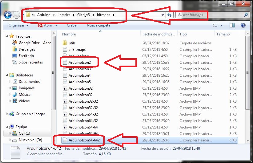
The two files must be saved in the folder bitmaps located in the library folder GLCD.h
Now it is necessary to do the programming that will be loaded in the microcontroller, for this I use arduino programming
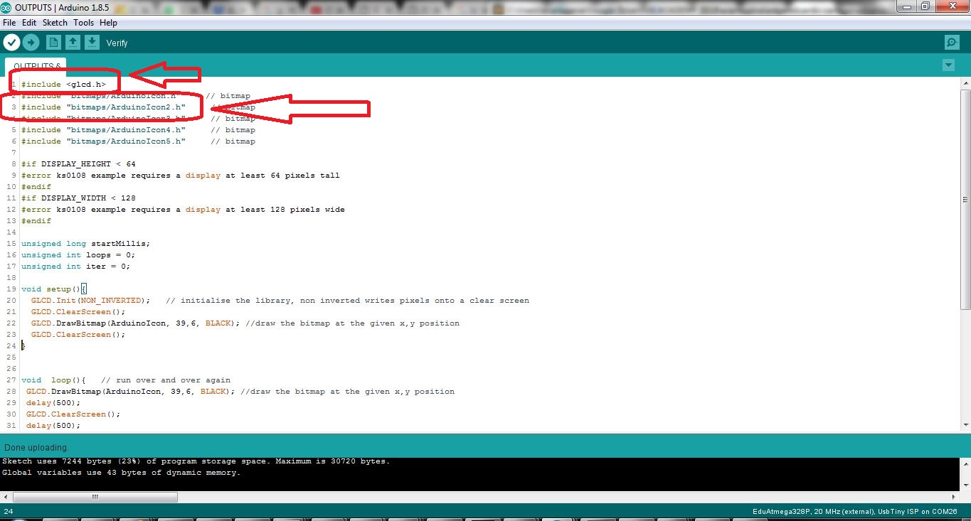
GLCD Arduino CODE
#include < glcd.h>
#include "bitmaps/ArduinoIcon.h"     // bitmap
#include "bitmaps/ArduinoIcon2.h"     // bitmap
#include "bitmaps/ArduinoIcon3.h"     // bitmap
#include "bitmaps/ArduinoIcon4.h"     // bitmap
#include "bitmaps/ArduinoIcon5.h"     // bitmap

#if DISPLAY_HEIGHT < 64
#error ks0108 example requires a display at least 64 pixels tall
#endif
#if DISPLAY_WIDTH < 128
#error ks0108 example requires a display at least 128 pixels wide
#endif

unsigned long startMillis;
unsigned int loops = 0;
unsigned int iter = 0;

void setup(){
  GLCD.Init(NON_INVERTED);   // initialise the library, non inverted writes pixels onto a clear screen
  GLCD.ClearScreen();
  GLCD.DrawBitmap(ArduinoIcon, 39,6, BLACK); //draw the bitmap at the given x,y position
  GLCD.ClearScreen();
}


void  loop(){   // run over and over again
 GLCD.DrawBitmap(ArduinoIcon, 39,6, BLACK); //draw the bitmap at the given x,y position
 delay(500);
 GLCD.ClearScreen();
 delay(500);
 GLCD.DrawBitmap(ArduinoIcon2, 4,10, BLACK); //draw the bitmap at the given x,y position
 delay(500);
  GLCD.ClearScreen();
 delay(500);
 GLCD.DrawBitmap(ArduinoIcon3, 8,0, BLACK); //draw the bitmap at the given x,y position
 delay(500);
 GLCD.ClearScreen();
 delay(500);
 GLCD.DrawBitmap(ArduinoIcon5, 4,11, BLACK); //draw the bitmap at the given x,y position
 delay(500);
 GLCD.ClearScreen();
 delay(500);


}
UPDATE
At the suggestion of Roberto Gallo instructor of Fablab ZOI, I have designed a shield that allows me to directly connect the graphic screen to the development board that I designed in the week of Interface and Application.
Software Eagle Design
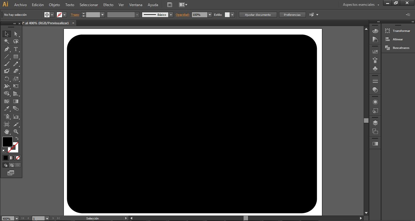
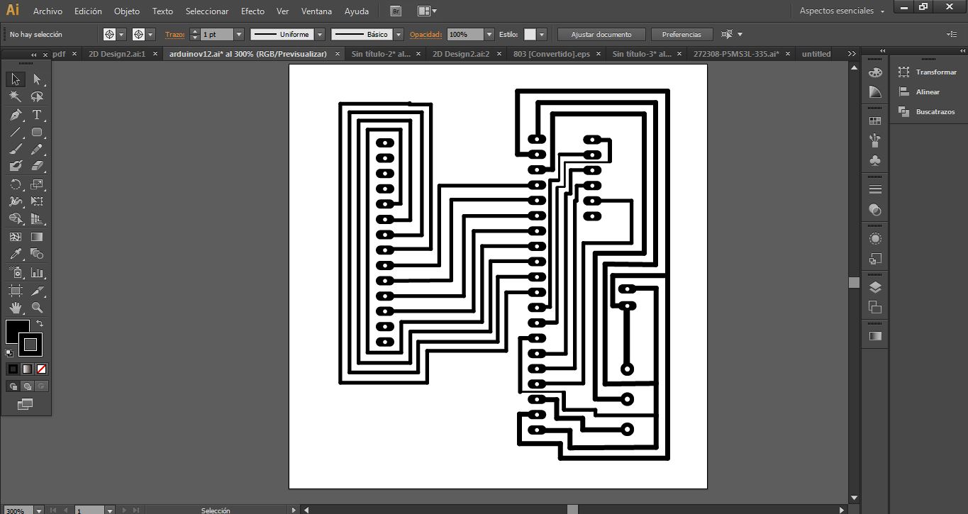
Edition and generation of PNG files in Illustrator software
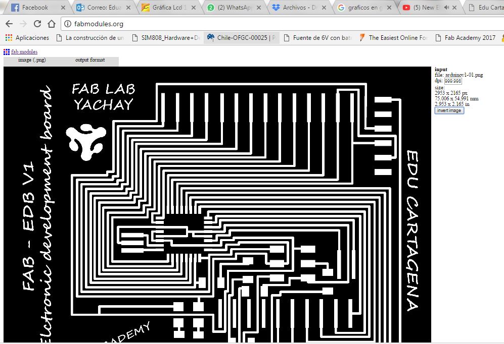
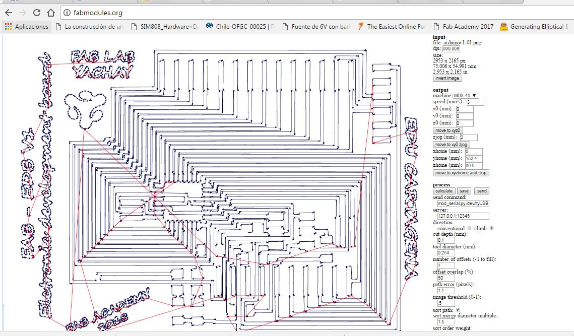
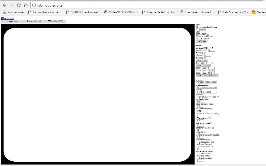
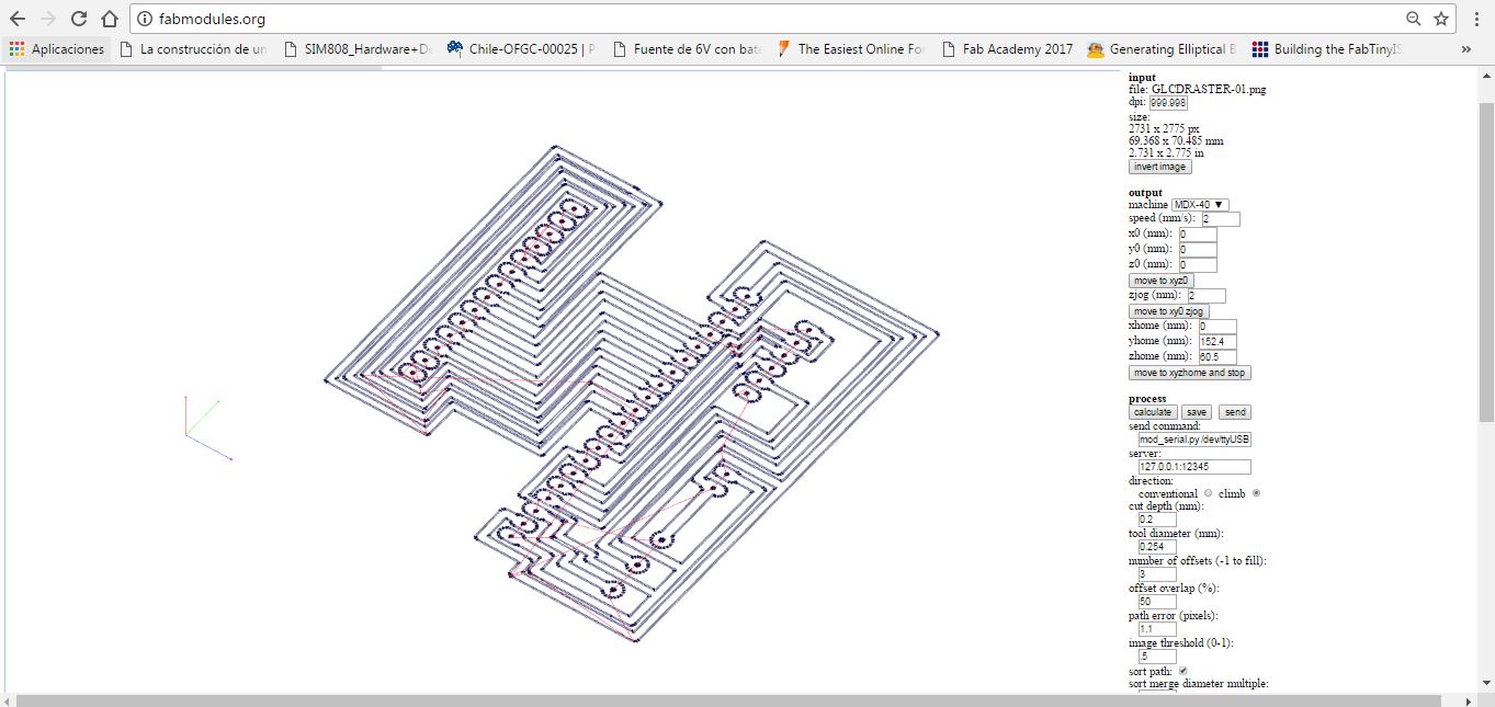
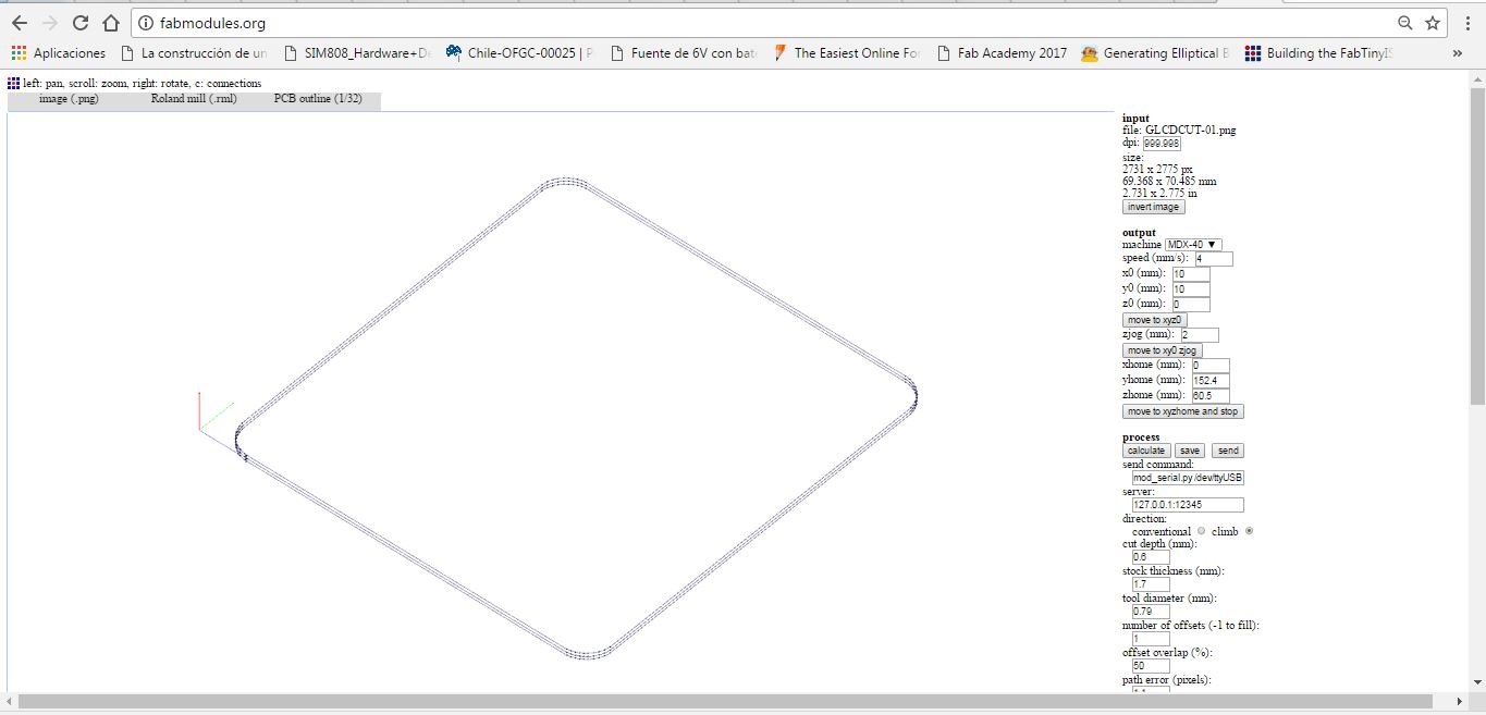
Generation of raster and cutting files in fabmodules
Fabrication in Roland machine
Assembly of electronic components and welding
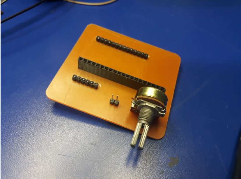
Test run

DOWNLOADS
- File 1: Eagle Files
- File 2: LCDAssistant
- File 3: GLCD Library
- File 4: Programming
- File 4: GLCD Shield