Lasers are a great tool in digital fabrication. They are reliable, fast and precise. That allow us to perform rapid fabrication in 2D and extrapolate that to 3D structures.
We caracterized our laser cutter as a lab project. The documentation is found here (link).
Learning outcomes:
Demonstrate and describe parametric 2D modelling processes
Identify and explain processes involved in using the laser cutter.
Develop, evaluate and construct the final prototype
Have you:
Explained how you parametrically designed your files:
What is a parametric software? According to Wikipedia, “Parametric design is a process based on algorithmic thinking that enables the expression of parameters and rules that, together, define, encode and clarify the relationship between design intent and design response. Parametric design is a paradigm in design where the relationship between elements is used to manipulate and inform the design of complex geometries and structures.”
For simple designs or sructures, I used to use vector-based programs, like Inkscape. However, the parametric design approach of other programs (Solidwoks, for instance), allow us to design over previous designs, and, with a change in the dimensions of one parameter, change other parts of the design that are inherently interdependant.
I chose Solidworks sofware for the development of the parametric design. I´m going to make a simple cube to get familiar with the program logic.
Shown how you made your press-fit kit
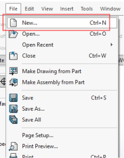
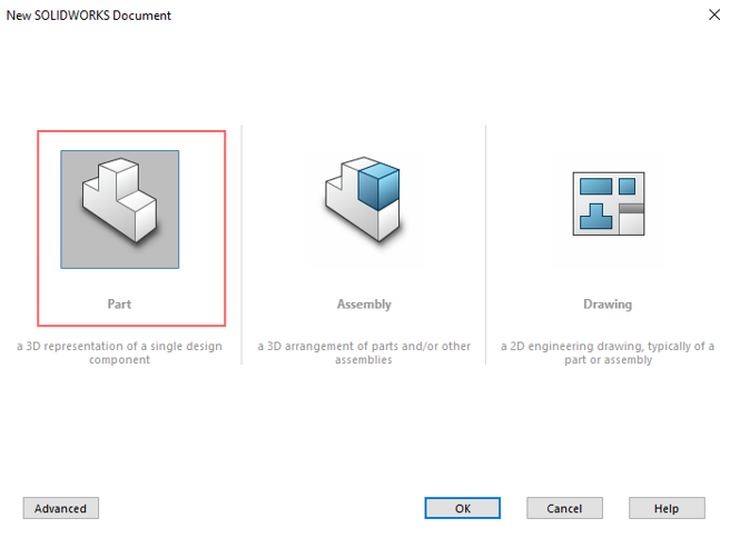
This is an overview of my workflow. First, we open a new part:
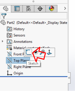
Right clic in top plane, and then choose sketch.
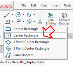
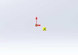
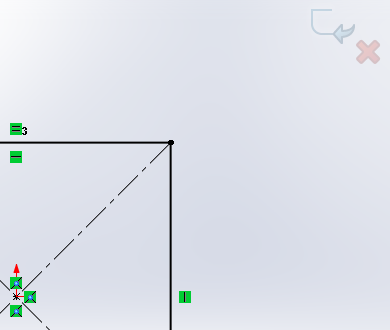
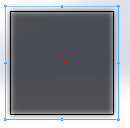
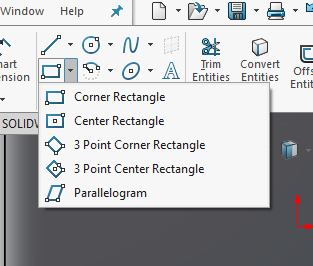
Now we are in the sketch. We start drawing a rectangle on it. First choose center rectangle, and clic in the origin. This makes our first relationship. The rectangle we are drawing is related to de origin. This help us to define our sketch, and technichally is the first parameter of our design.
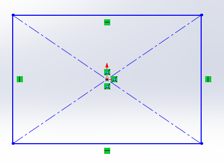
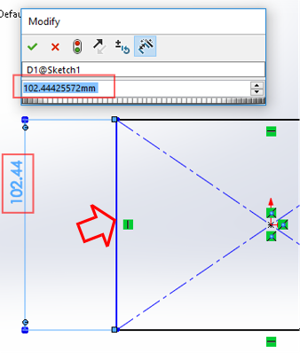
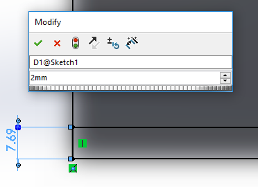
With a right click in a blank stage area we have de menu. Pick smart dimension, and then make clic in the first vertical line (in blue and with an arrow). We choose an arbitrary size. I chose 100mm (10cm) because of laser cutting bed limitations.
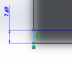
Pick a vertical line and dimesion it. Clic just in the line.
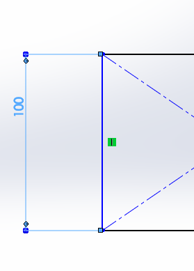
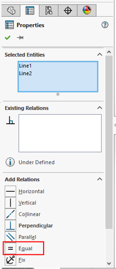
We are going to use this measurement as a parameter. We could add another 100mm measurement definition, but instead, we choose the dimensioned line and an horizontal line (with the convention Hold-ctrl/clic), and we choose equal in the menu that appears related to our two lines choice.
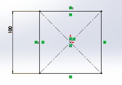
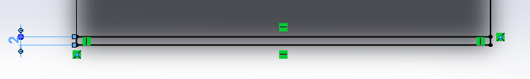
Note now that all the lines in the sketch are black. That means that it is fully defined (this is good). We centered our first sketch in the origin. A good thing about parametric design is that the rest of the geometry of the part or the assembly will be related to this position in the 3D space. Another advantage is the symmetry we could make using the default planes. Always is possible to create more planes, but in this case, less is more.
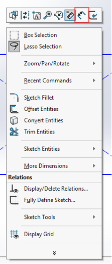
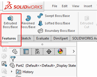
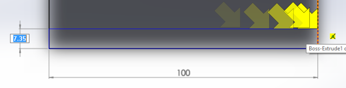
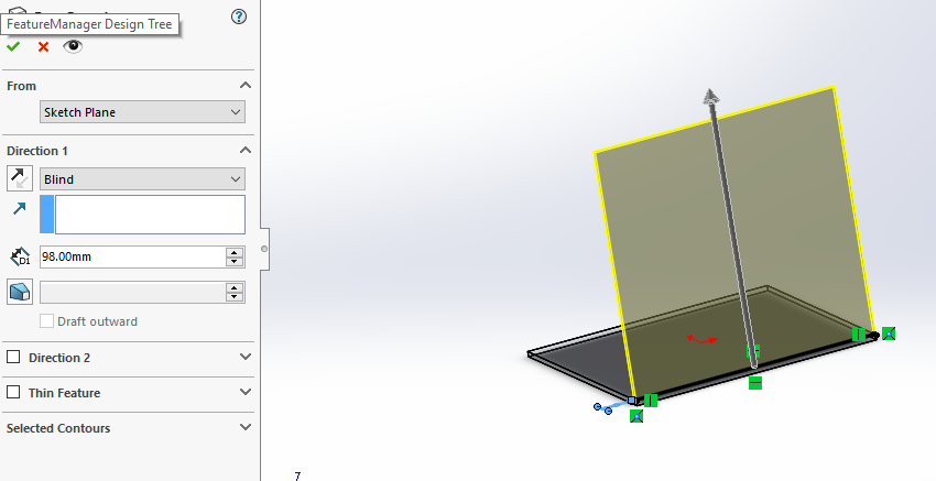
Don't leave the sketch (clicking in the icons marked in the corner). Instead, choose Features-Extruded Boss/Base to project our sketch into the 3th dimension.
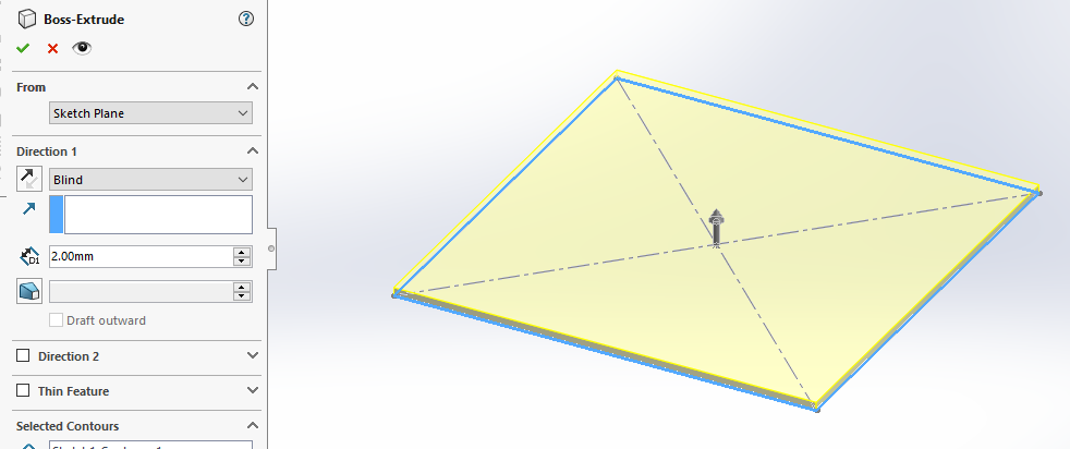
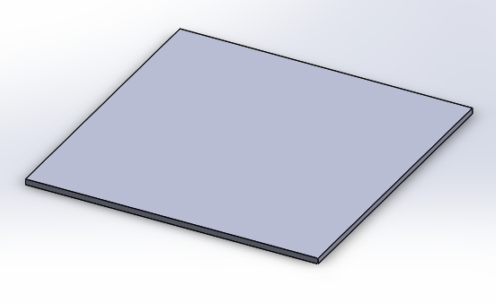
Here we can see before and after assigning a height to the part. Now it is a 3d object. Note that the volume is defined by the input parameters of our x and y coordinates of the square sketch. If we change the 100 cm by, for instance, 200 cm, the square will rebuild it's equal side (defined by the relation equal. Furthermore, we can make also this height equal to our first measurement assigment. In this case we are not going to make that. Maybe in the future we want to vary this parameter also, and we don't want it linked to the square side.
Instead, we are going to assign here the thikness of the material. One interesting thing about parametric design is that if, for instance want to cut a material with 3mm thickness, we just update this parameter and the size of the slots will all match the size of the tabs. This design suposes a thickness of 2 mm.
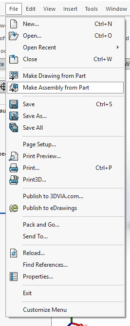
Now, we start our top-down design approach creating an assembly form this part. This is going to be the base of our cube, and the other pieces dimensions are going to depend on the dimension of this part. We create the assembly clicking Make assembly from part, from the file menu. Click on the green check button. This is going to lock our first Part to the assembly center. This is a good practice, and is going to save us mates problems that otherwise might occur in the future.
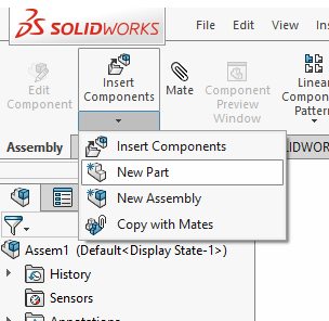
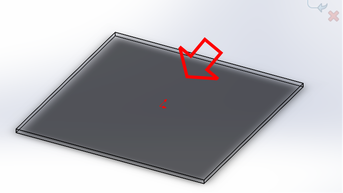
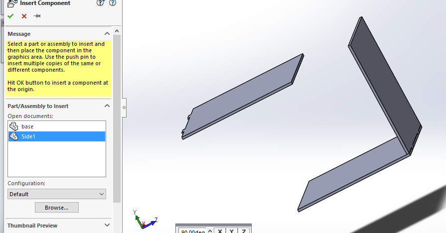
Once in the assembly, we click in Insert Components-New Part. Then we clic in the surface we want to create the new part. Then click on the upper surface of our base. Note that the part becomes transparent. It means is a reference. We are going to create a side part using this geometry. The upper surface is marked with an arrow.
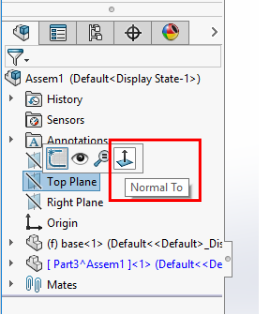
For an easier estimation, I recomend working in a view normal to the plane we are working with. This is optional, but it's done this way, if desired:
This time, our sketch will be a corner rectangle. Using a gemometric figure based on corners allow us to use the lines of the other part as a reference. Start in just the corner of the underling part/sketch. This will automatically add a relation between this new rectangle and the old one. Precision is the name of the game.
This is a tutorial for Top Down Desing. I found it very demonstrative.
This time, our sketch will be a corner rectangle. Using a gemometric figure based on corners allow us to use the lines of the other part as a reference. Start in just the bottom left corner of the underling part/sketch. This will automatically add a relation between this new rectangle and the old one. Then, extend the square dragging as marked with a yellow arrow, until it matches the vertical line of the right side. Be aware of the change of the cursor icons. This will define in context the sides of the new part. This is going to be the thin side of the part, the one that makes contact with the base part, in 90°.
Dimension it with a 2mm (thickness of the material). It's a good idea to reference this dimension to a variable, but we are not going to do that in this review.
It's fully defined, as we see it in bold black. We proceed with the extrusion:
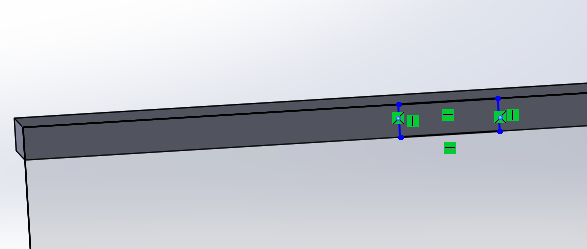
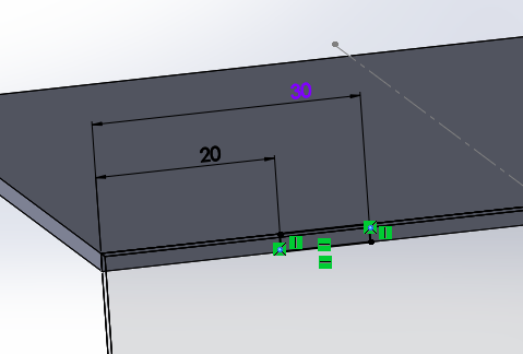
Click Modify Element, and then click in the part named base. Then, clic in the 2 mm border to schetck in this plane a rectangle to be extruded as a tab. Dimension it as shown.
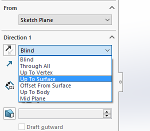
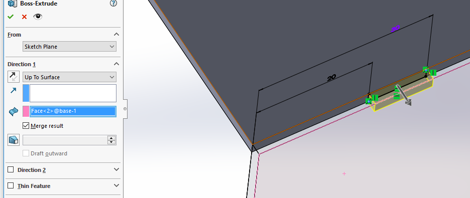
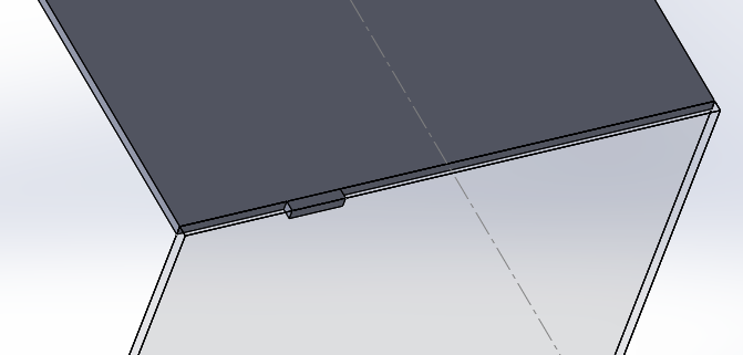
As in the previous case, it's fully defined. We proceed with the extrusion:
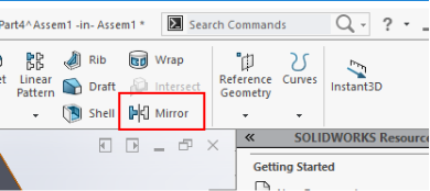
Let's mirror the feature we just created.
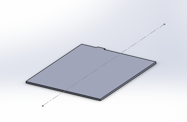
We are going to mirror the feature about a plane that intersects the costruction line, here in dotted line.
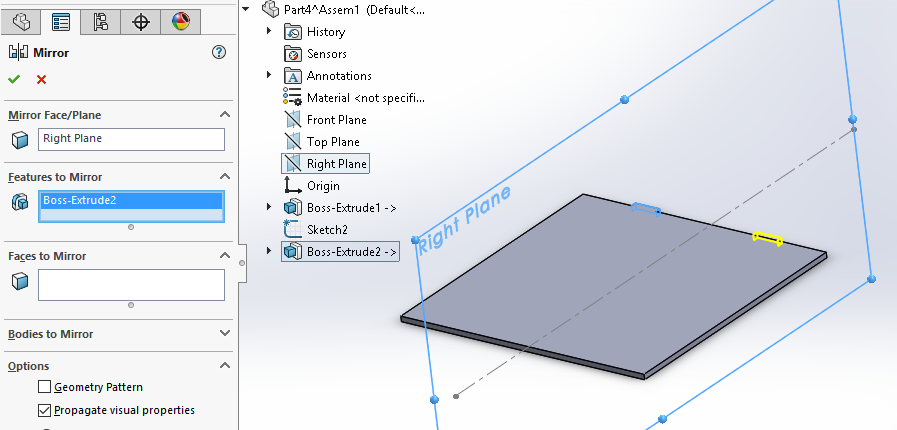
Mirroring using the right plane as a reference, and the tab feature as a features to mirror input.
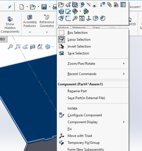
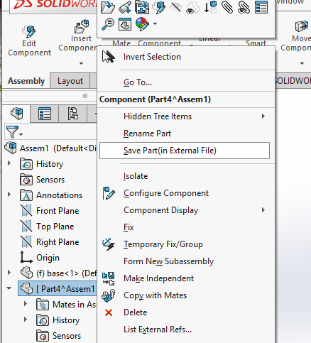
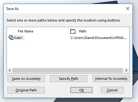
Our part is virtual (we can tell because it's enclosed in brackets). This is a good moment to make it real. Let's save it as External.
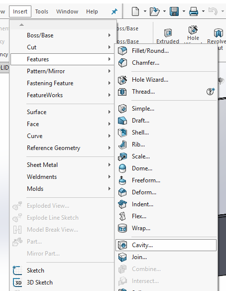
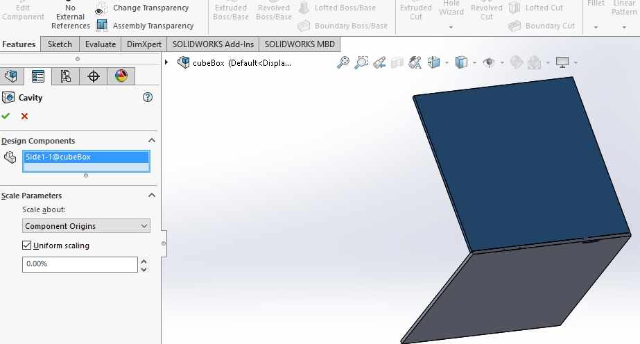
Now, our parts interfere with each other. We are going to use the cavity feature to "cut" the tab in our part, making a sloth with the operation.
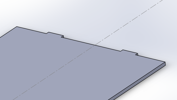
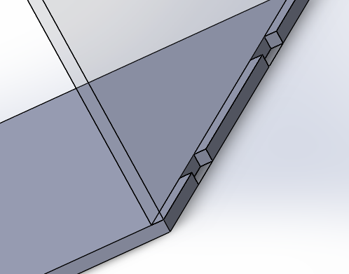
Here we can see what the cavity operation did to our part. There's no interference now. We repeat the process for creation and extruding tabs with the other parts (faces) of the cube.
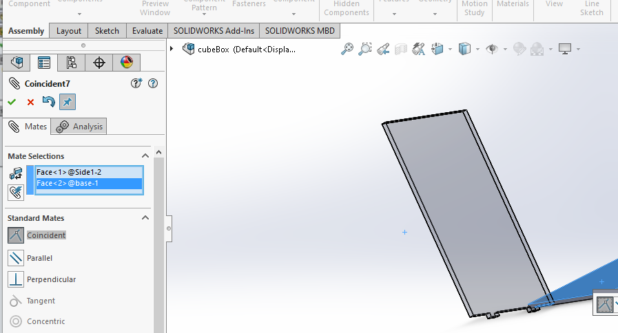
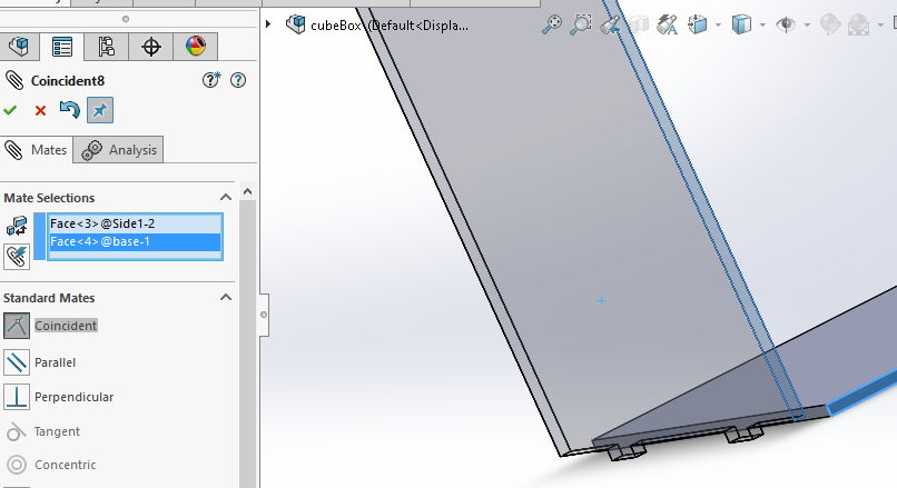
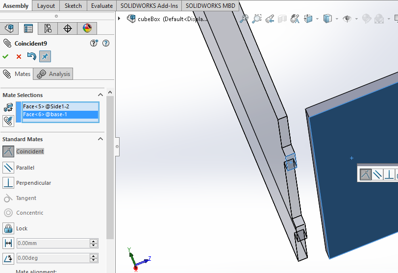
But first, we need to mate the new staged part. We need to mate three dimensions. Is easy to do so using the faces of two parts in each axis. Make two, move the part, and you are going to have a 3D idea of what is happening.
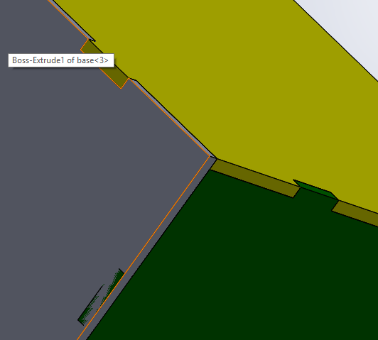
After mating the next part, we can see how the interference looks like:
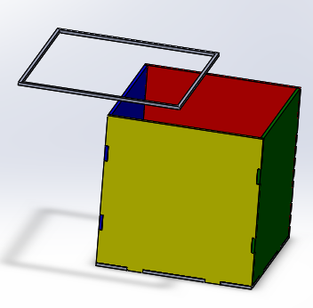
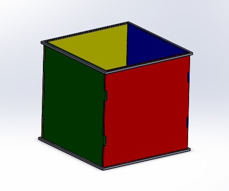
After fixing the interferences, we have our basic cube. It is posible to get creative at this point, and I though two rings could help to hold the structure together and make it more robust. As before, the context design makes it quick and easy.
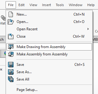
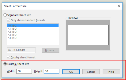
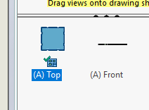
Our file is ready in 3D. Now, we are going to export it to a 2D file based on vector graphics. First, we make a drawing from an assemby. We choose custom size, and set the size according to our laser cutter bed. In this case, 30 cm by 60 cm. Keep all part documents open.
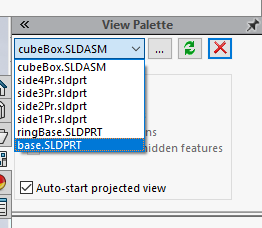
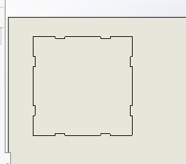
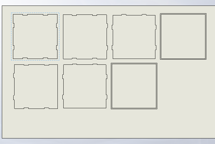
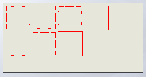
We choose our part and our suitable view for cutting.
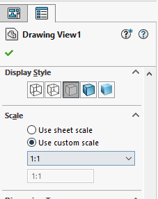
With a clic in our first view staged, we check the scale. Should be 1:1, oterwise you will get funny results.
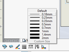
Then, we choose all the lines in the stage (check filter edges, shorcut F if necessary), and make them hairlines. In this case, 0.18 cm.
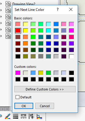
We do the same for the color. It should be solid red in order to the machine to read it as a cutting line.
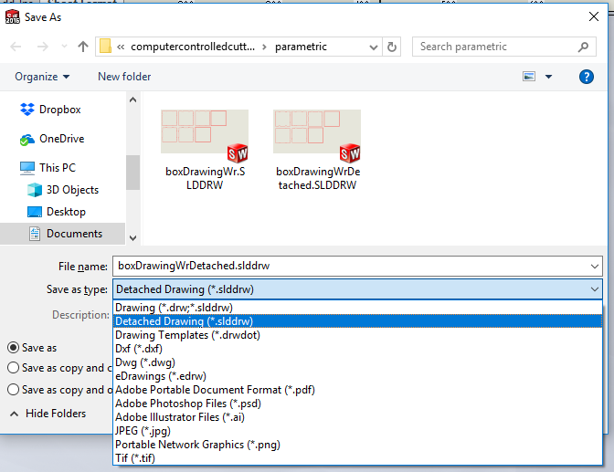
Finally, we save the drawing for cutting. I recomend saving it as Drawing (for future editing), Detached drawings (so I can take it with me to upload it to the machine), PDF file (some cutters read this kind of file), and Adobe Ilustrator files (for the same reasons).
Included your design files and photos of your finished project
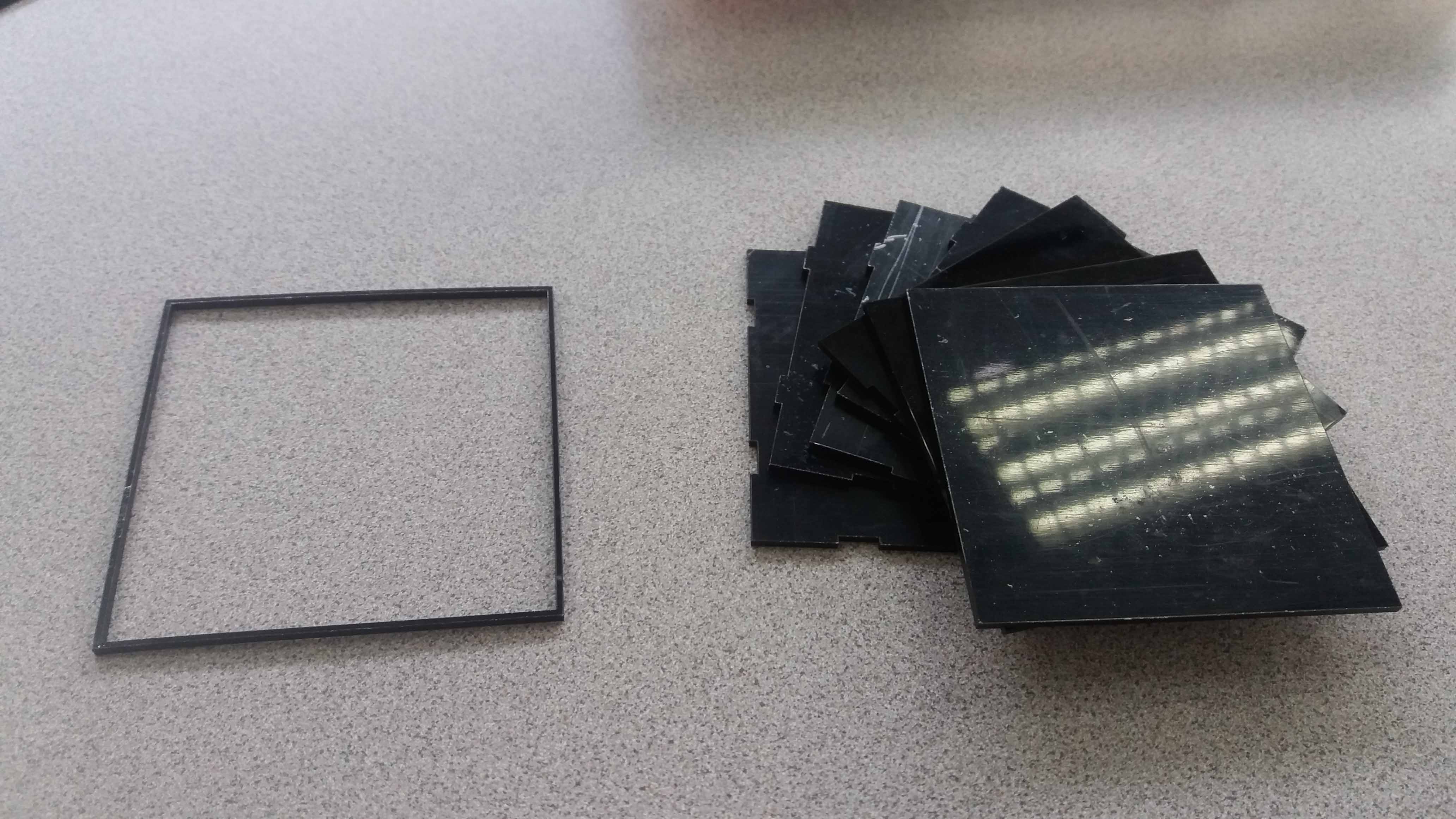
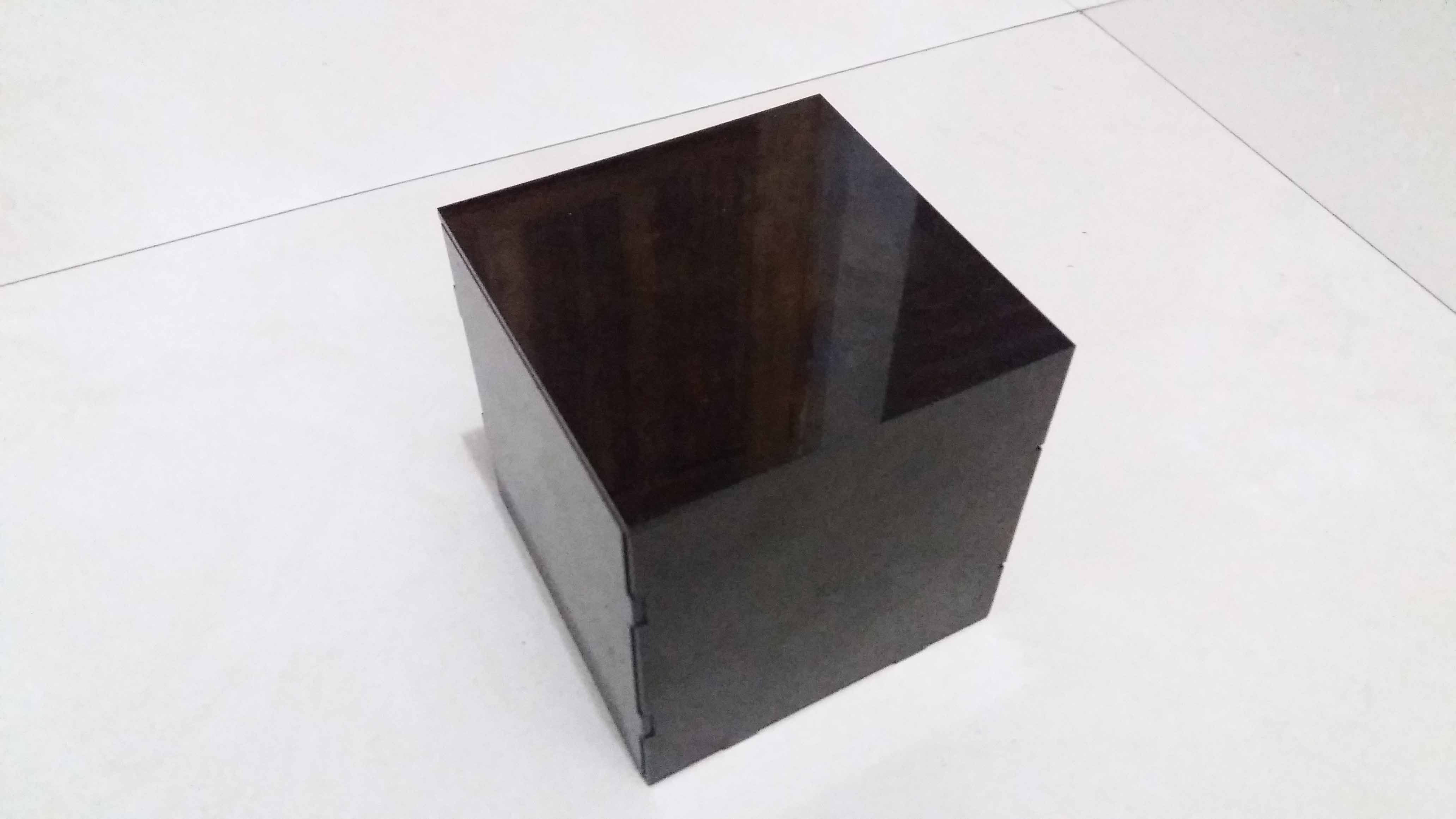
Here are the model pieces, cut in black acrylic. The model holds itself by gravity, but there is no much friction, due to the properties of the material.
The pieces are hold by scotch tape. Then, a few drops of glue (technically, solvent), are aplied to the junctures. The bond is prety strong. Could even support a the weight of a person. It is also good for hermetic construcions. I tested it with water, and there are no leaks.
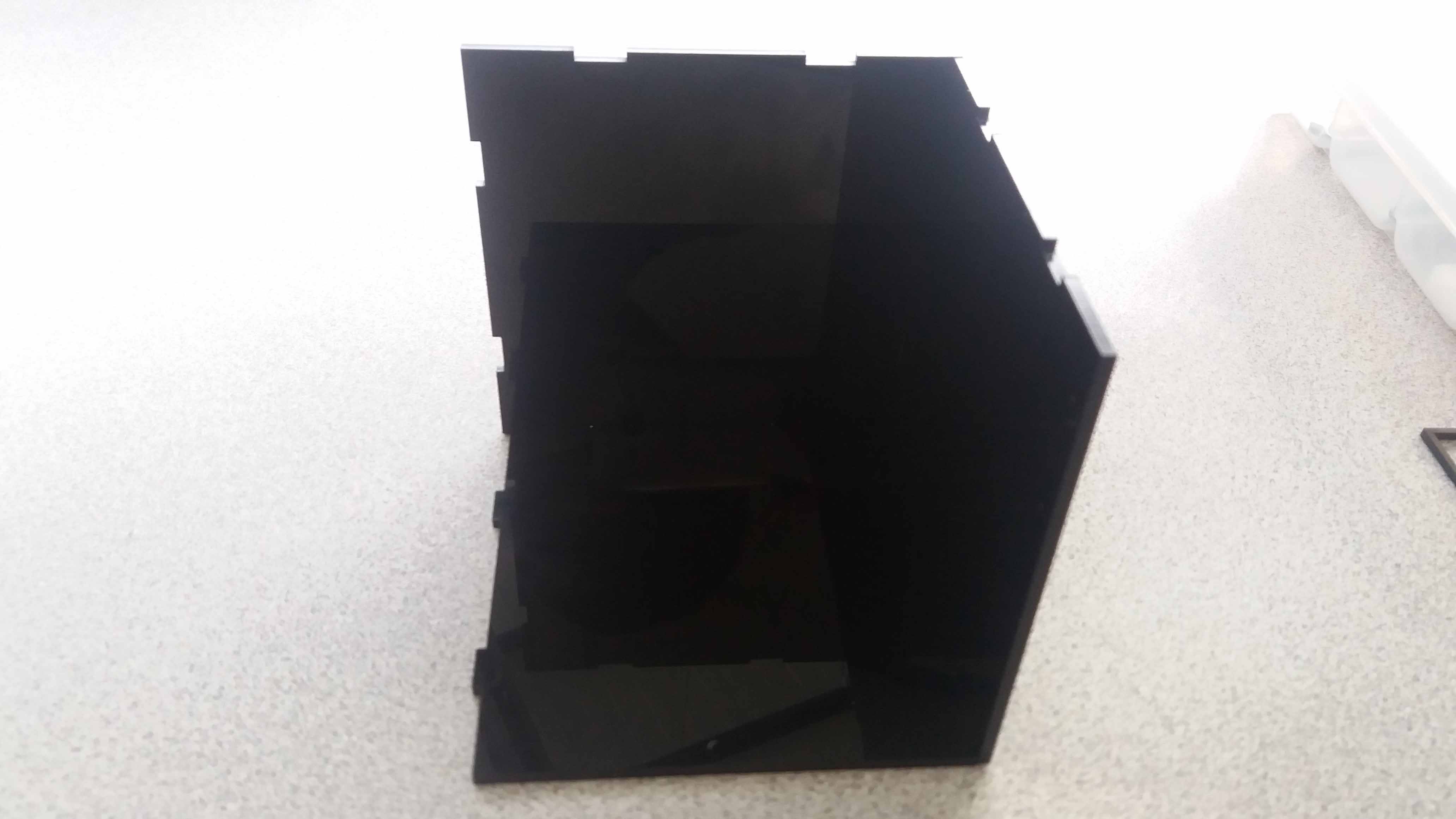
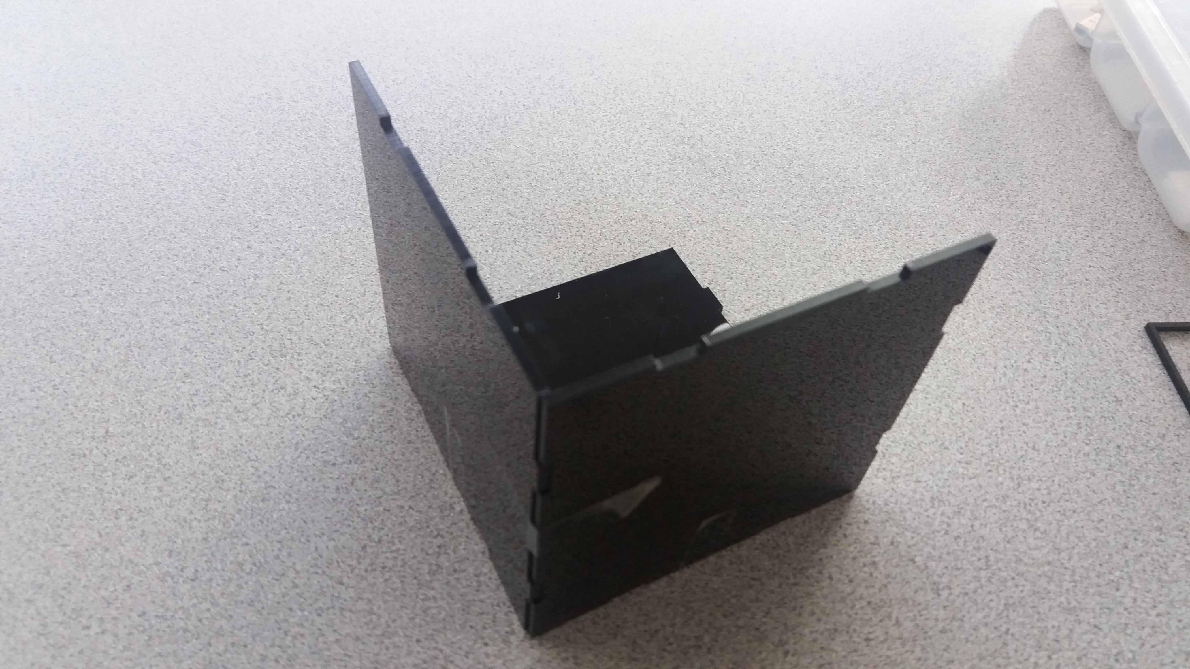
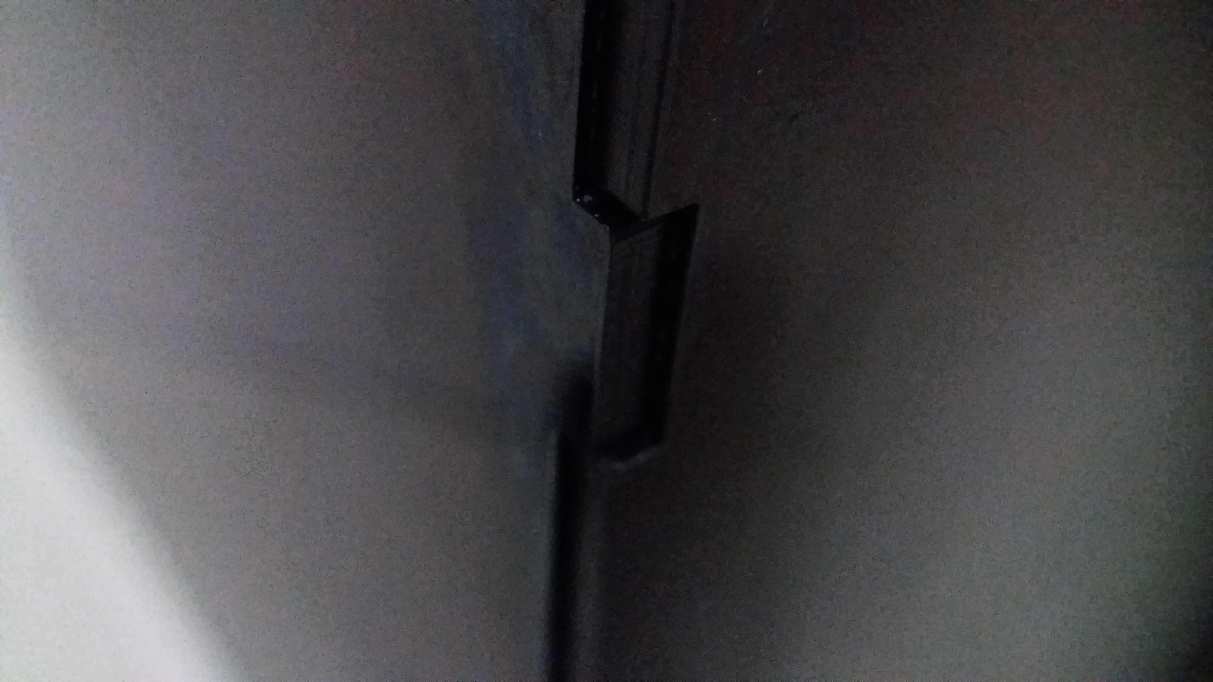
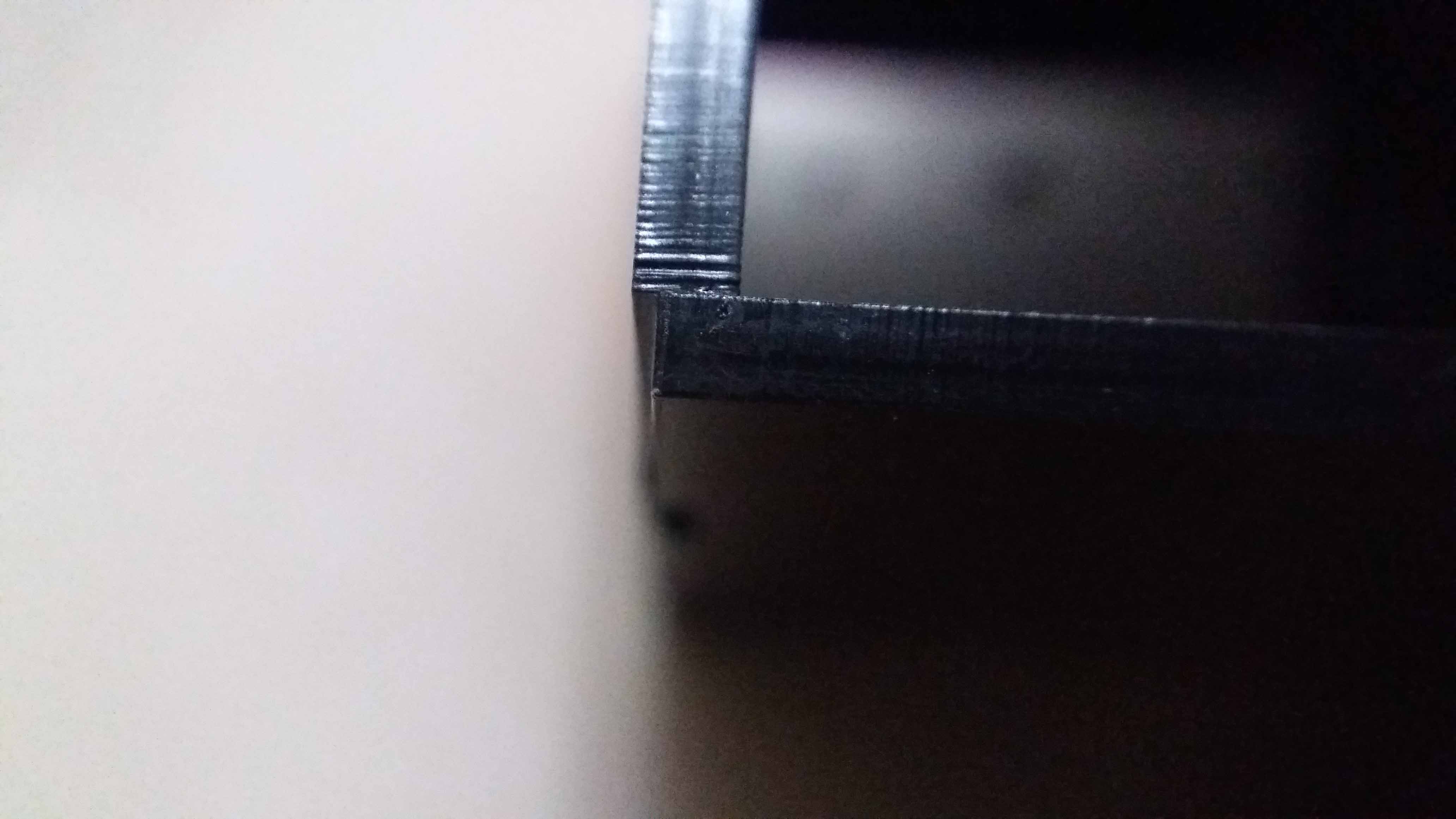
Finally we have the piece ready. We can see that, eventhoug the material specification stated it was 2mm thick, in reallity it was 2,2mm. Those 200 microns become evident in the final product.
Here we can see the ofset due to lack of thickness double check. Even with the kerf in account, we still see the mismatch. In this case, it didn't affect the wather thightness of the construcion, but it affected the aesthetics, and the square piece to reinforce the structure became useless.
Variable construction kit
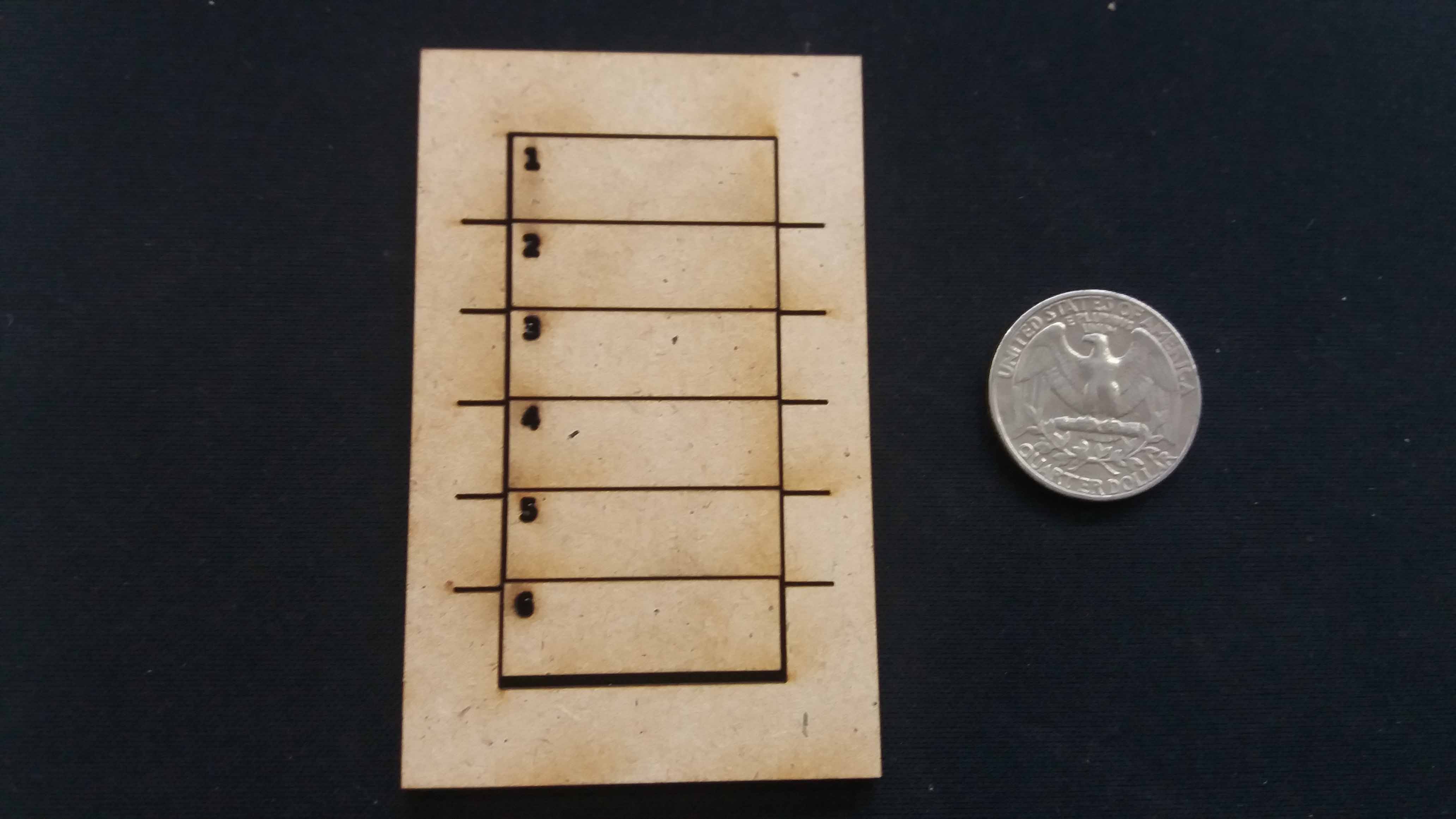
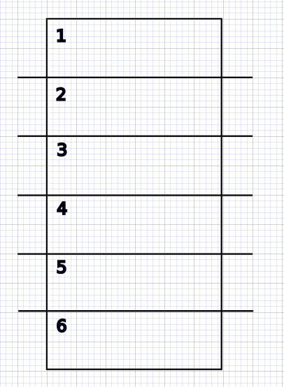
We used this piece to calculate the kerf of the material. In this case, MDF. The technic here is to cut the rectangles, join them together, measure the resulting gap, and then divide by the number of rectangles.
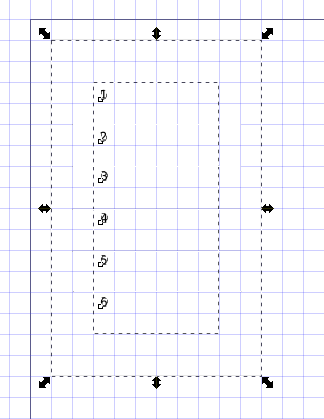
The design:
We reduce the width of the line, so the laser recognizes it as a cut job.
This is the value of the line in mm (very thin).
We can also create a pressfit kit to define the kerf. Here are the files for that method: Fit test SVG (Inkscape), Fit test PDF. Then we design our kit with the kerf found.
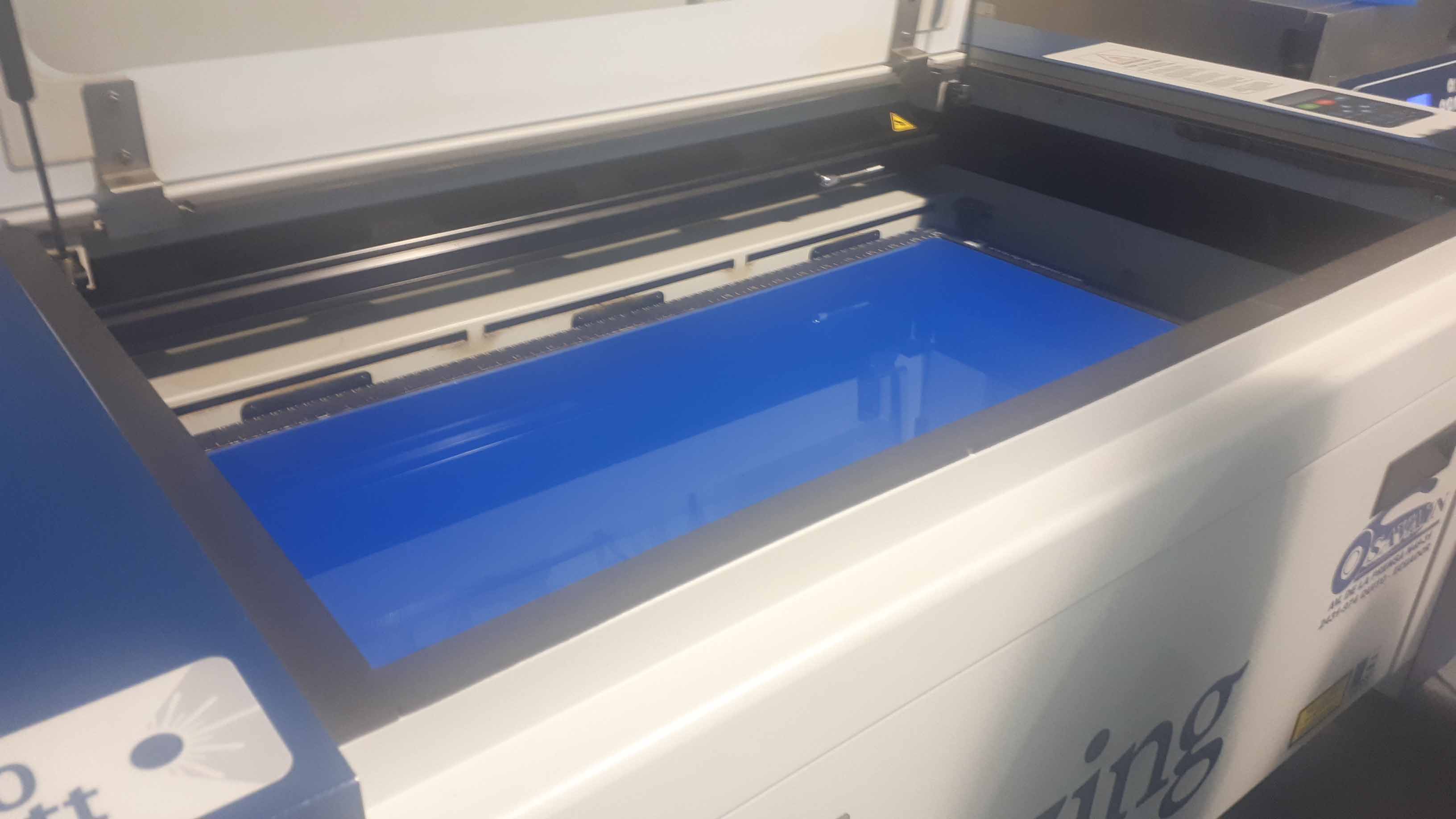
But before we proceed to cut, we are going to know our lab's machine.
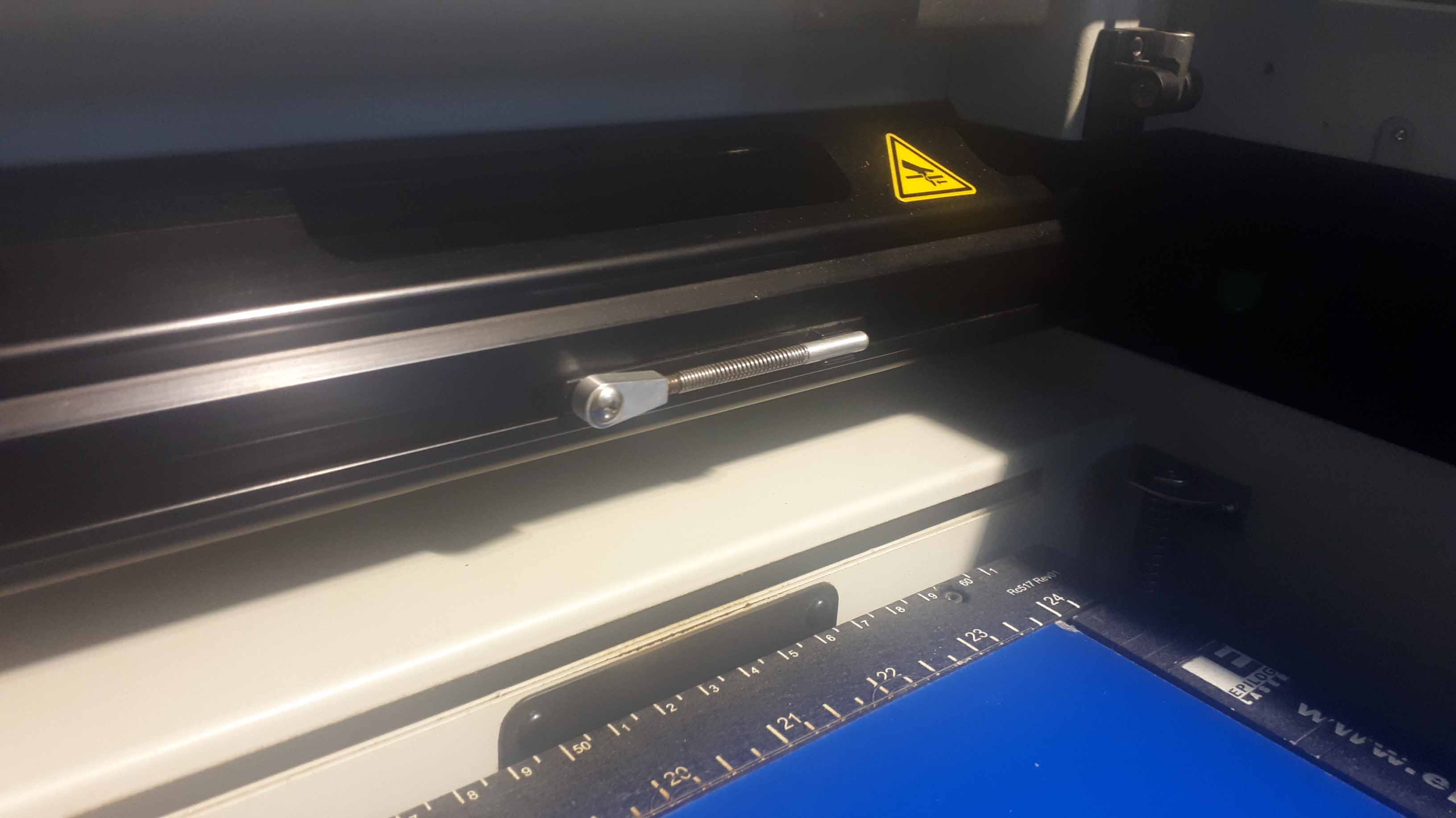
In our lab, we have the Zing Laser 24 (for 24 inches). In metric, the bed size is 60cm by 30cm.
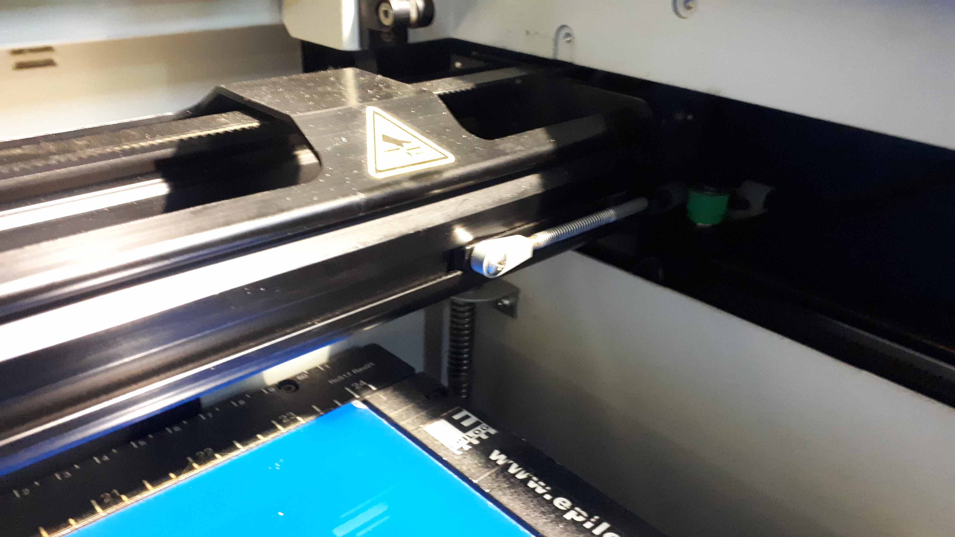
Then, we proceed with the focusing. For this endeavor, the Zing machine has a device set with the lenght of the distance between the laser emmiter and the material in the bed.
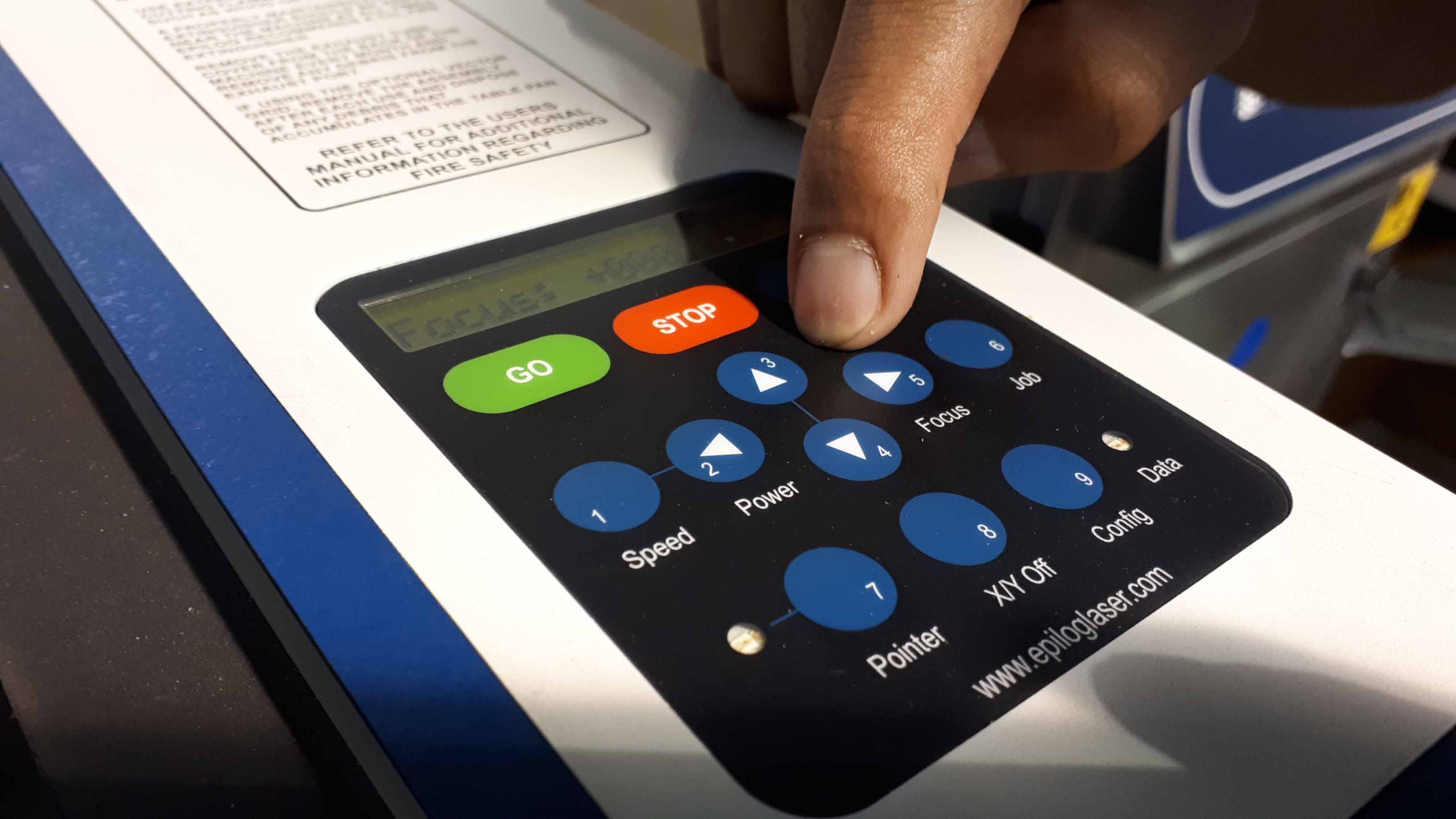
We free it from the rail and press the "focus" button in the console.
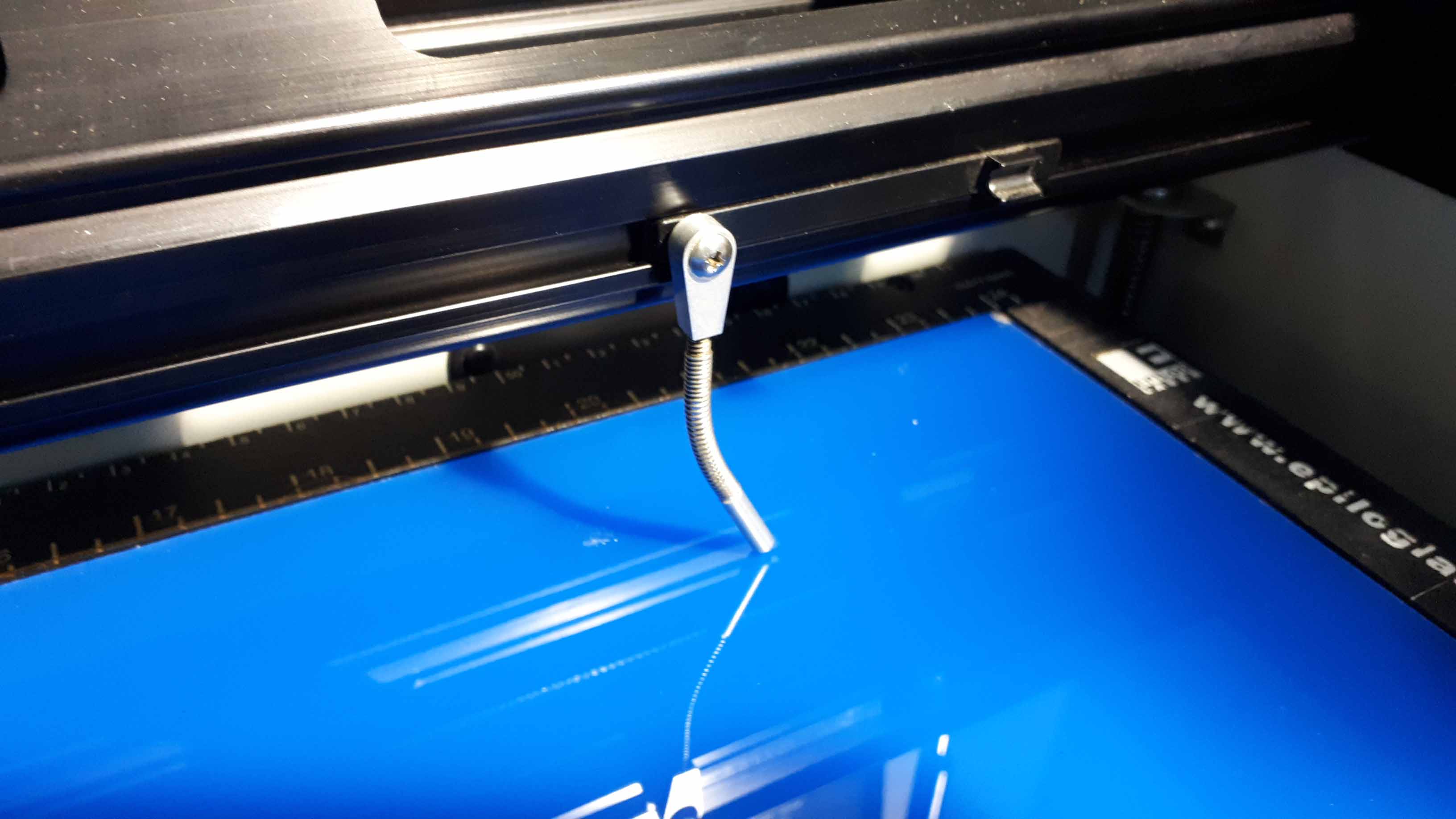
Then we use the up and down arrows in the console to adjust the height of the bed. If the probe bends, it is too close.
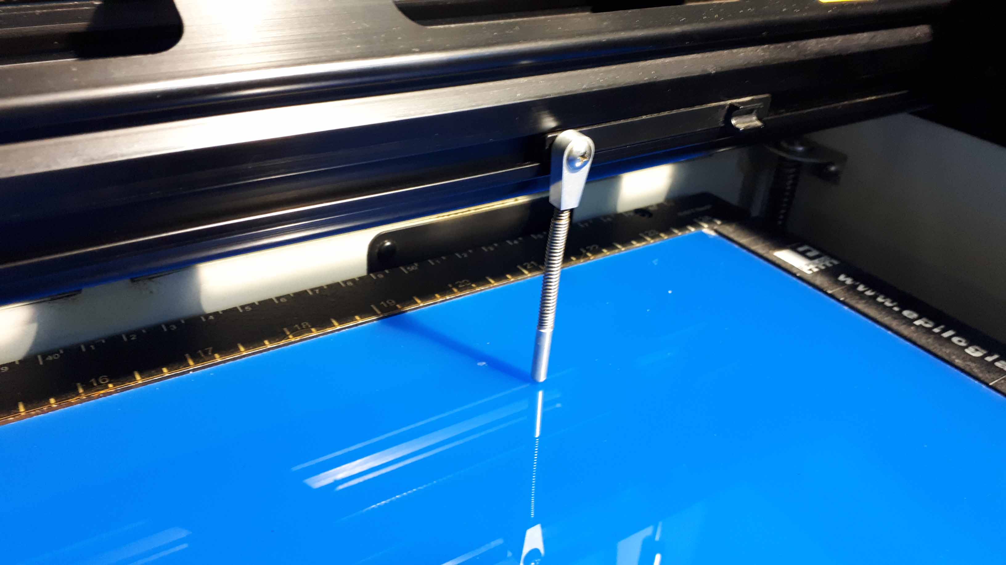
We raise the bed until the probe barelly toches the surface of the material we are going to cut.
Once it is done, we press reset to record this distance.
Then we place the probe in it's rail again.
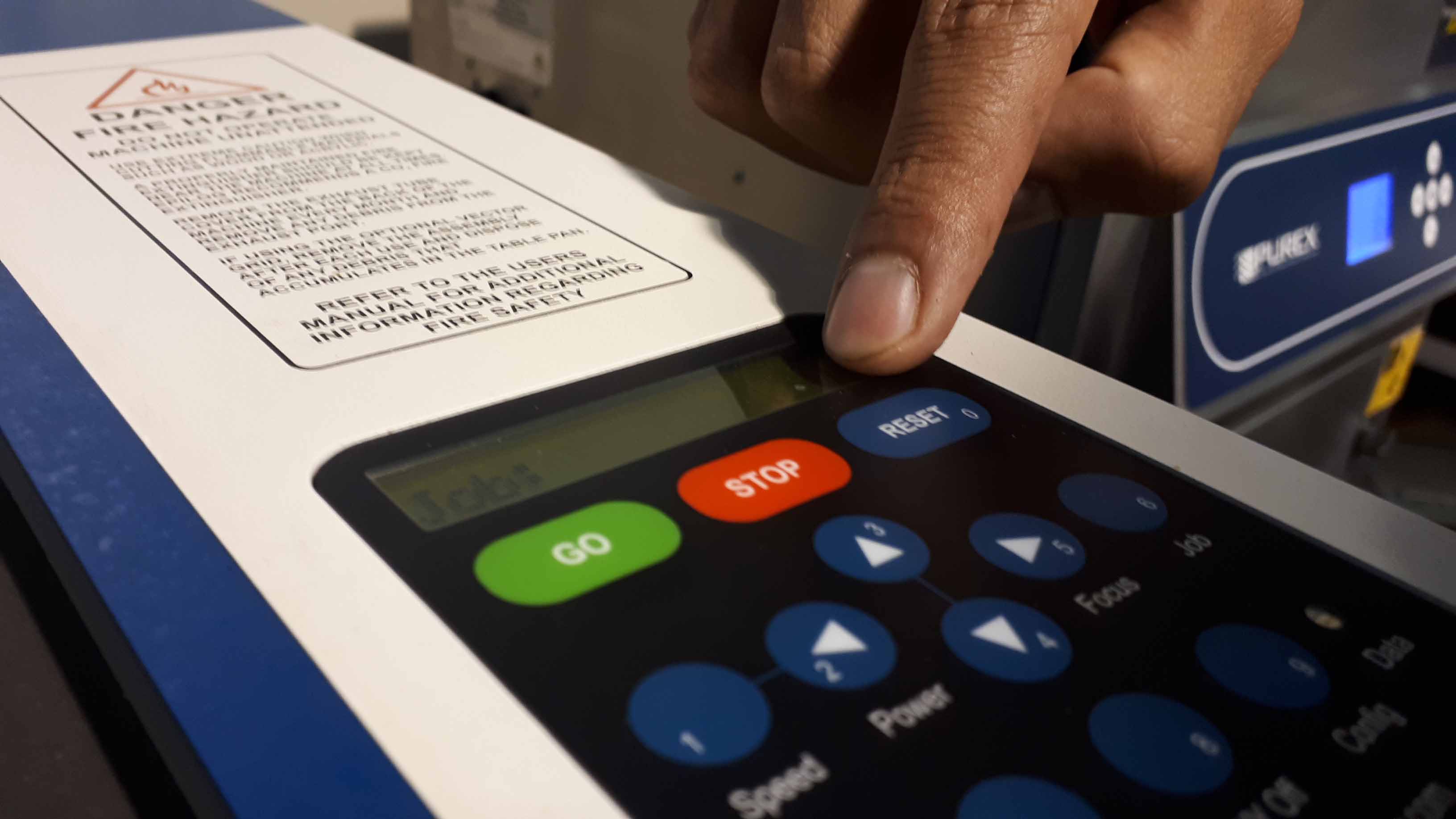
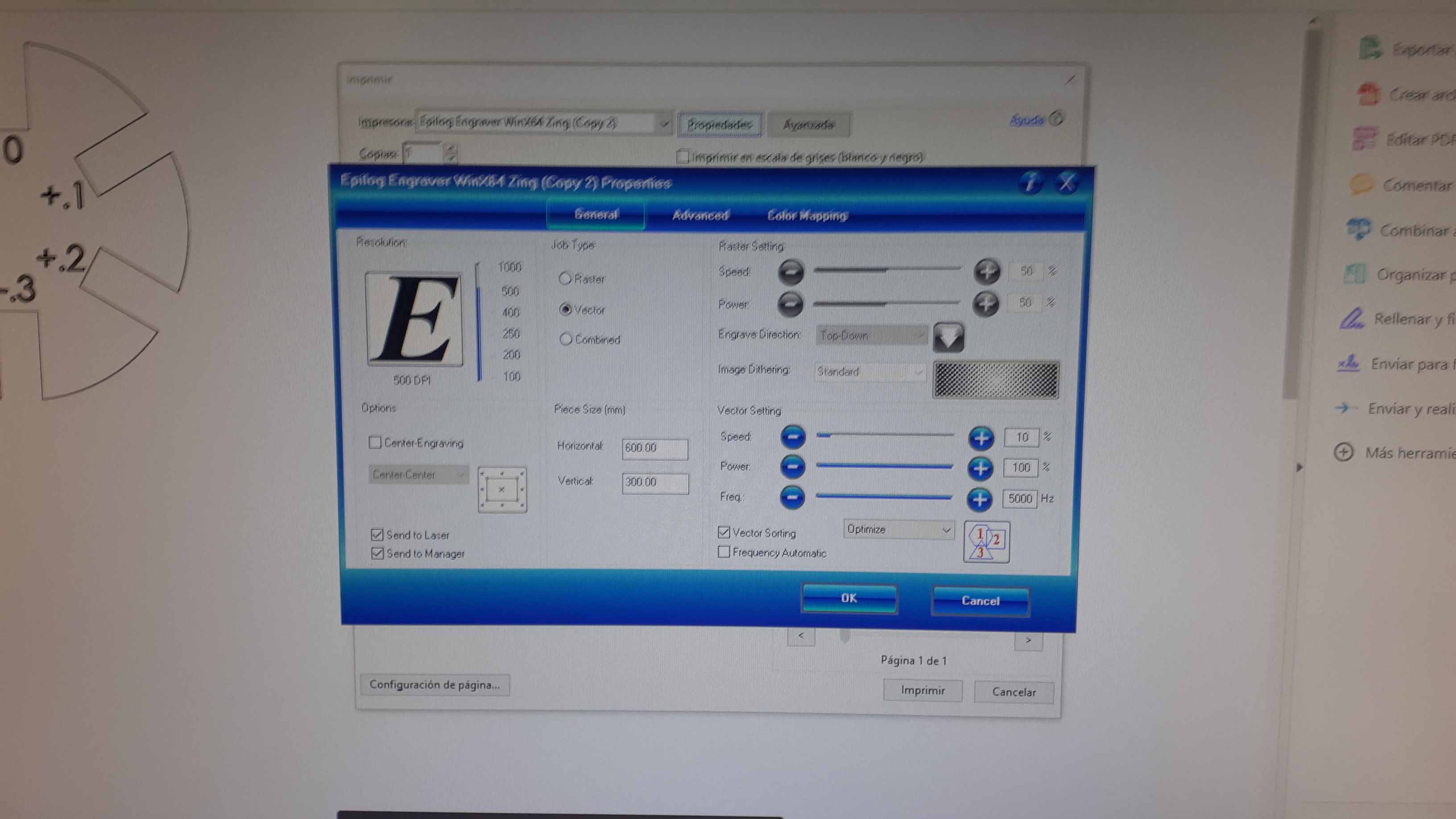
Finally, we send the cutting/rastering document as if we are going to use a normal printer. This machine works with PDF documents, so we export it in this format. On the macnhine screen we will see the job number and the name of the file.
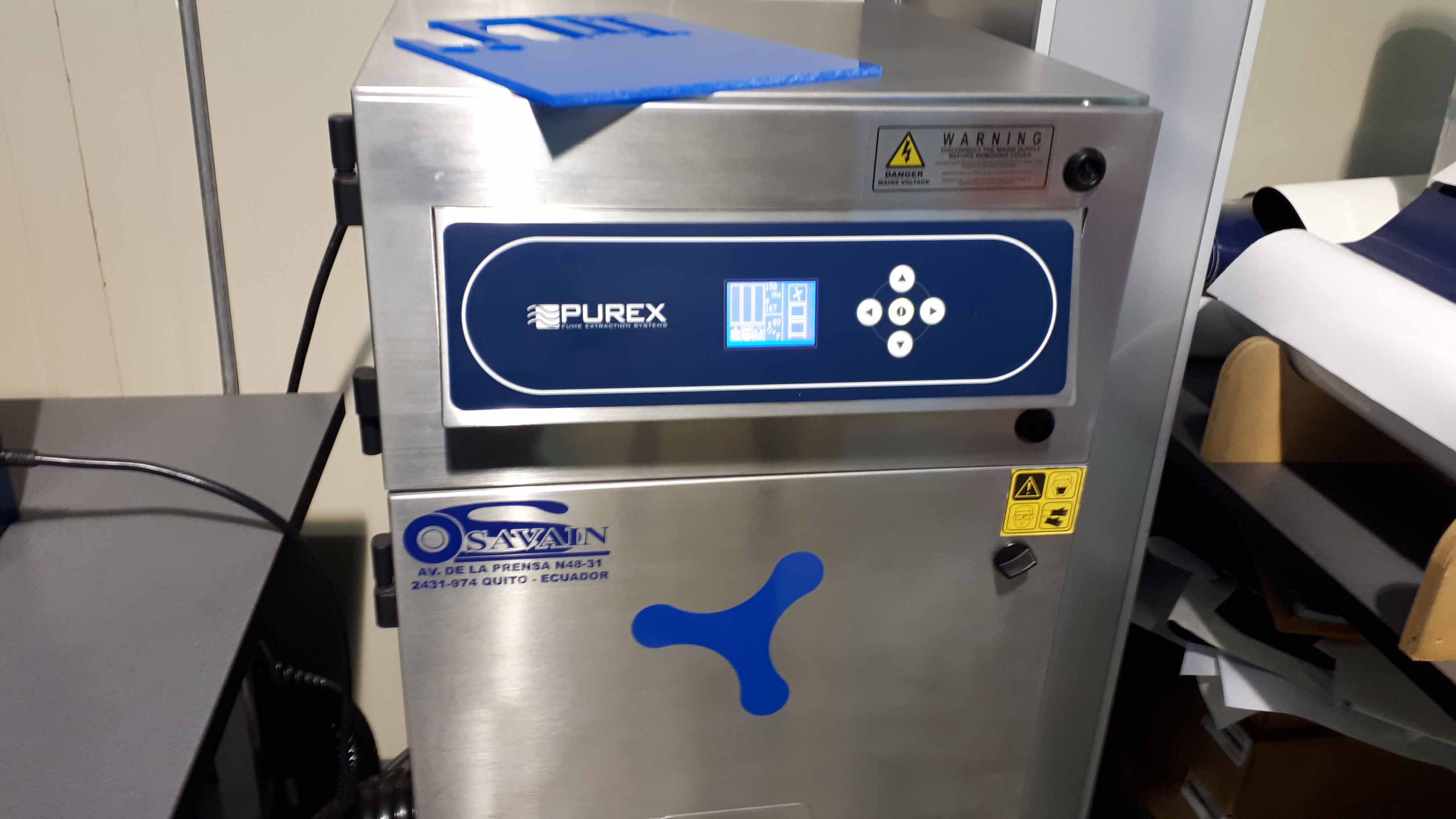
Then, we can confirm the job with the "GO" button in the console. But before confirming, we need to be sure the fumes extractor is in operation. Turn it on if it is not.
After the security check is done (extiguisher close and identifiable, extarctor and pumps on), we confirm every thing is allright, and press "GO".
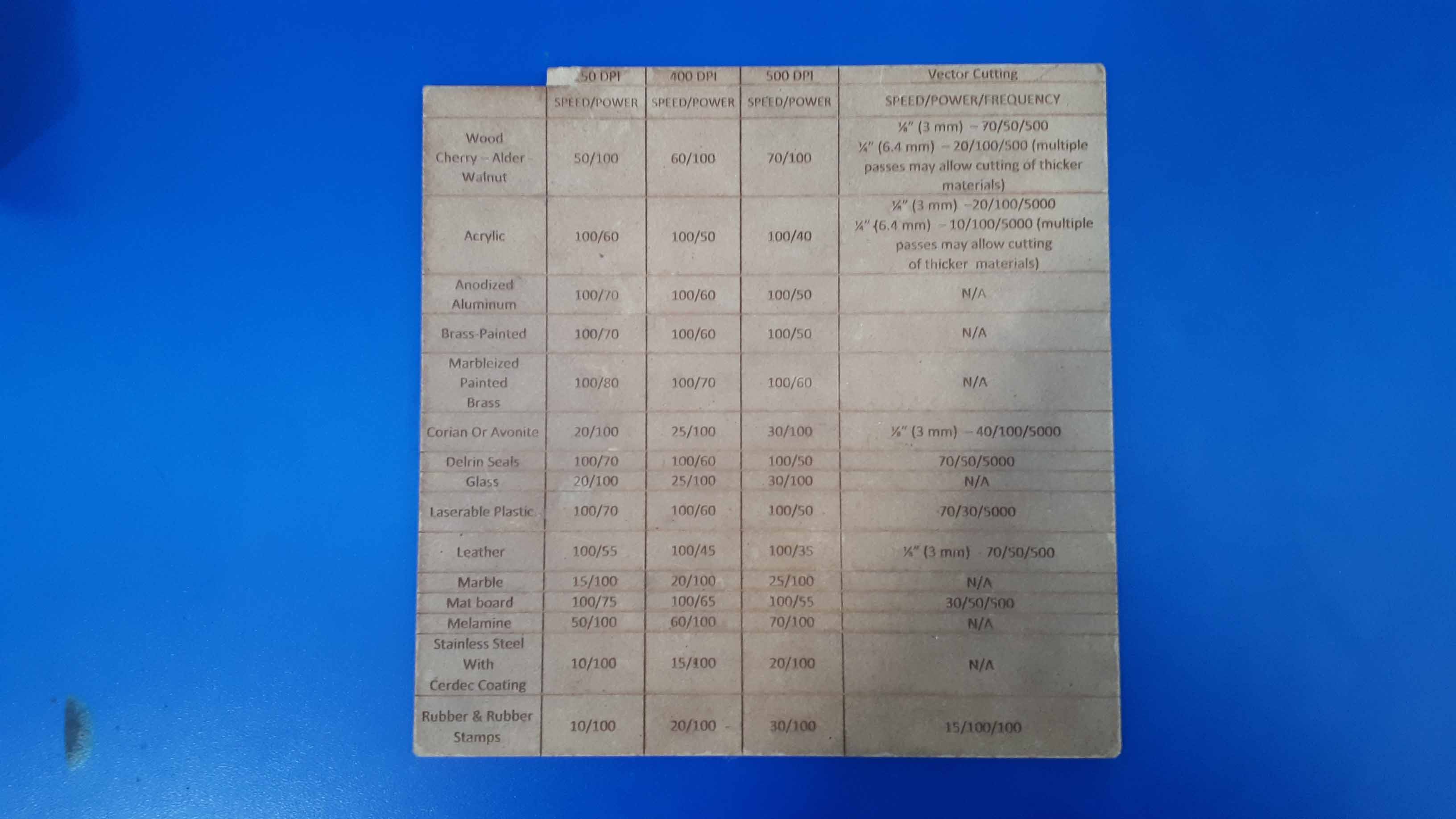
Different materials require different settings. In this case, for acrylic of 6mmm we use a speed of 10%, a power of 100% and a frequency of 5000Hz.
For defining the kerf of the machine/settings/material, it is convenient to perform a test to see how well the pieces work together. I made a wheel with increments of 100 microns between sloths. We have a table that has come from previous experience with the machine.
Once everything is ready, we proceed with the cutting.
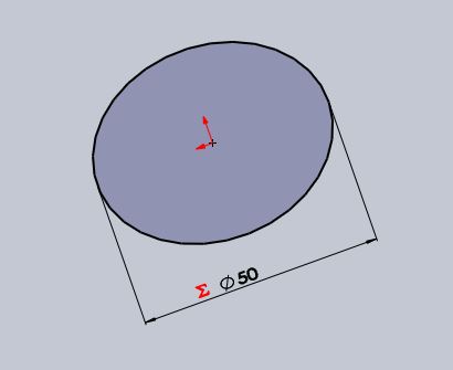
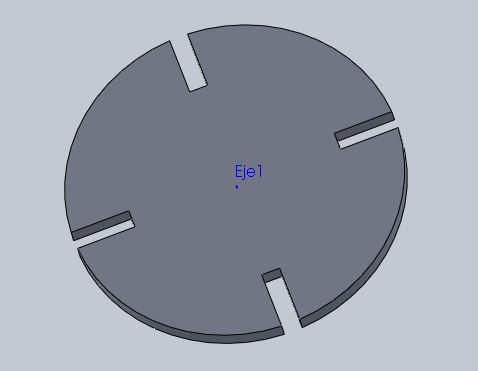
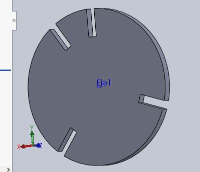
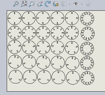
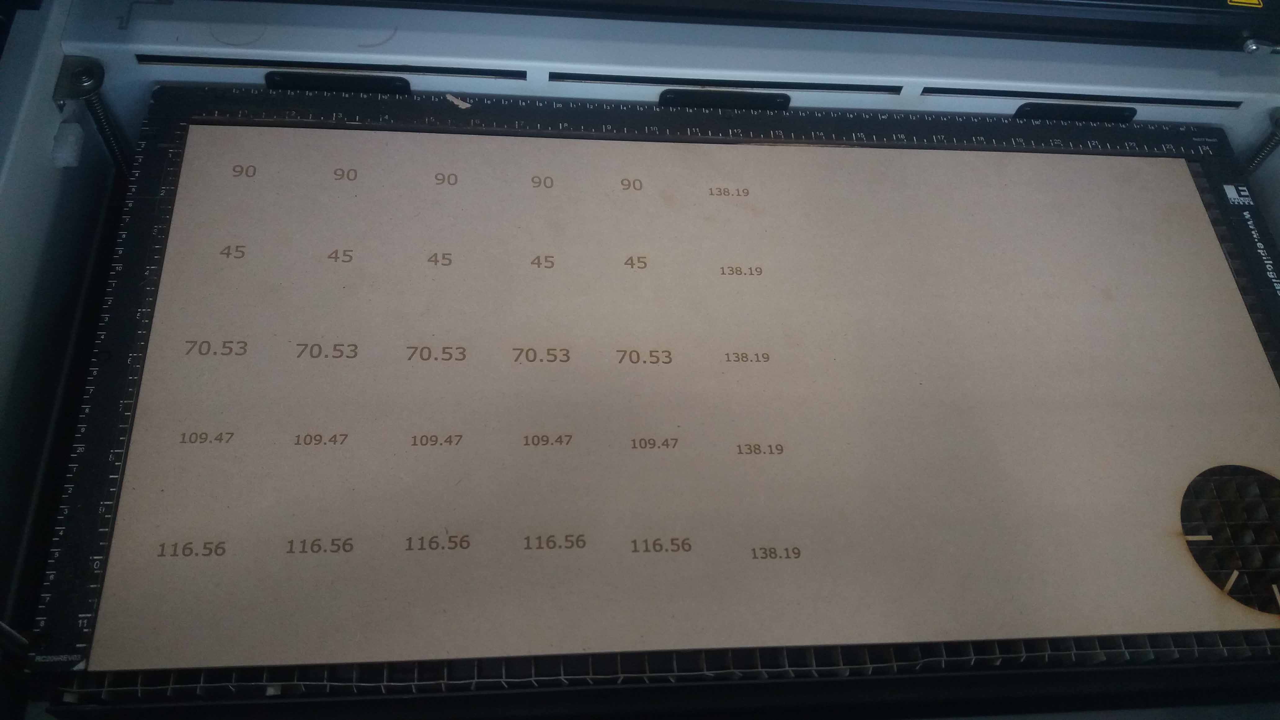
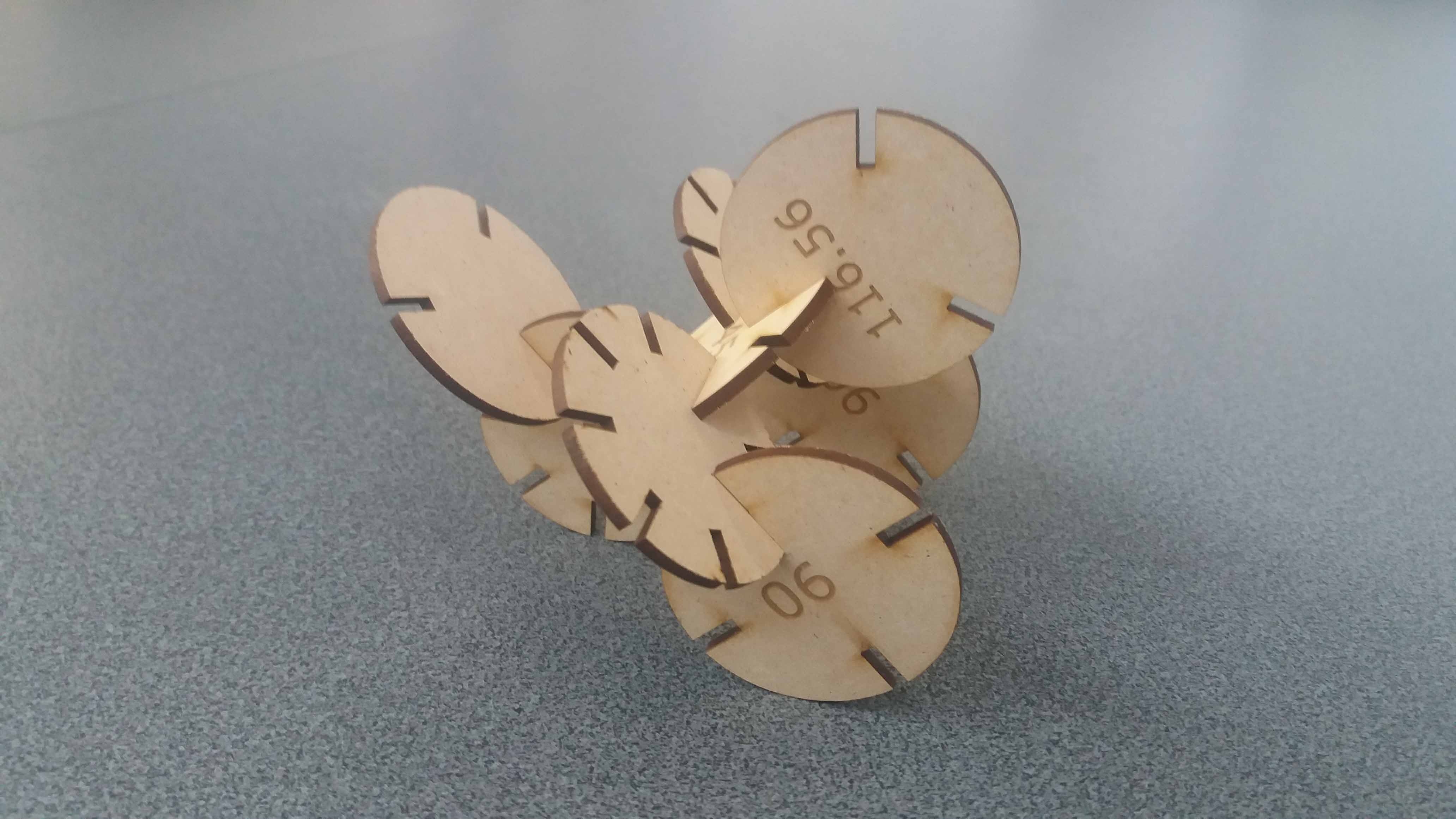
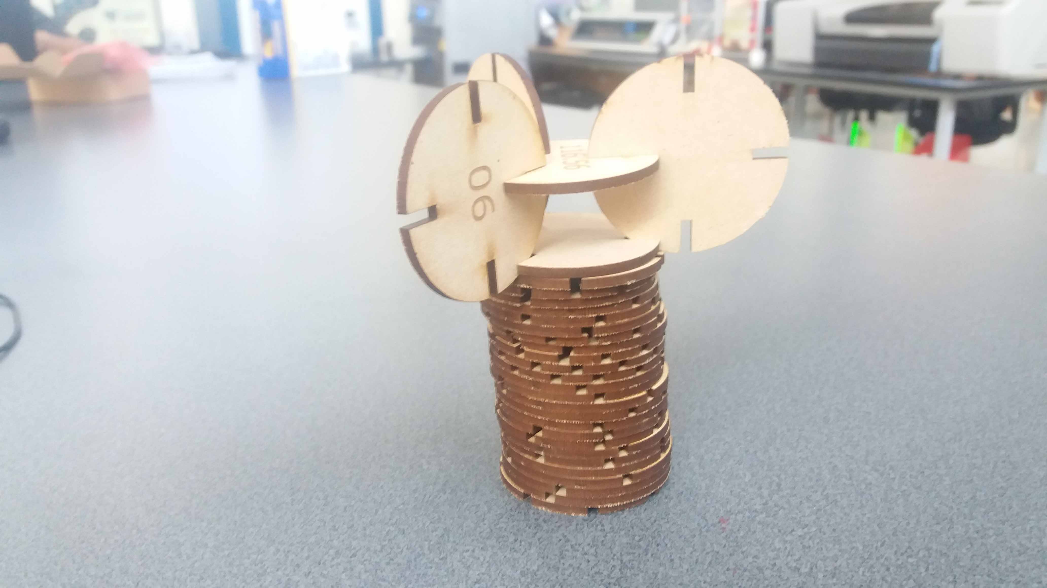
For the pieces, we cut angles based on the Pythagorean/Platonic Solids, to explore the geometry. We make a circle, and extruded it to a parametric thickness. Then, we set the angles according to the table of Pythagorean/Platonic Solids, and create a circular patter with the instances we need. We repeat this for each variation, and then we make five copies of each in a solidworks drawing (set to the size of the cutting bed). We export it in SVG format (we actually could start designing in inkscape for this type of file, but Solidworks is usefull and easier for the task of generating patterns). Then we exported the file in various formats (files available latter in this document. Some machines read PDF files). We also engrave numbers with the angles, accordingly.
Parametric design for multiple assemby kit:
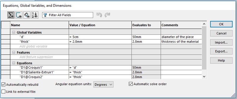
This is a basic, demnonstrative design. Eventhough, we still can (and should) make it parametric. This can be useful if the future user (me or someone else), wants to alter parameters like here, the diameter of the pieces and the thickness of the material. The first might change depending on the goal of the user, the second always change, as even the same providers have different thickness depending on the batch.
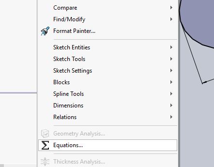
First, we have to define our parameter(s). We find the Equations tool under the Tools tab, in Solidworks menu top list.
There, we can set the parameters we want. If we need to change them, we can come back when we need it and the changes are going to be reflected (re calculated) in the main design (providing there are not geometry conflicts).
In the part itself, we can set then our diameter using the equation/variable we set before. Notice the sum symblol in red fefore the diameter dimension.
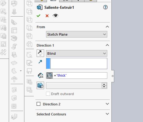
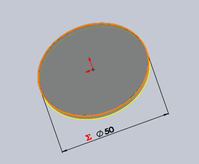
Then, we extrude the part using the thickness ("thick") parameter defined in the equation table.
Then we proceed with the extrusion. Here is not shown, but the thickness will be the value of the variable "thick", and it will change, if we make changes there.
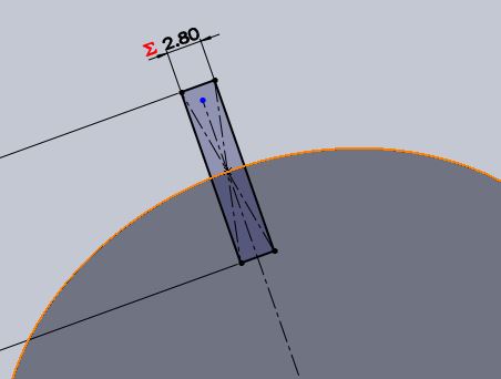
For cutting the sloths, we are going to need the "thick" parameter. This is important because the sloth must correspond with the thickness of the material, and if it changes, the widht of the sloth also have to change, so it will fit with this variable parameter.
Finally we made the cut and the circular pattern. All the sloths have now the necessary width. The number of the sloths can be also parametrically set, but we are going to use angles in this project, so we left it as a by case setting.
We do the same for all the part variants.
And the pattern reflected in the 2D file. Note that, even if we generate a 2D file, the 3D settings help us with variable thickness material issue, at least.
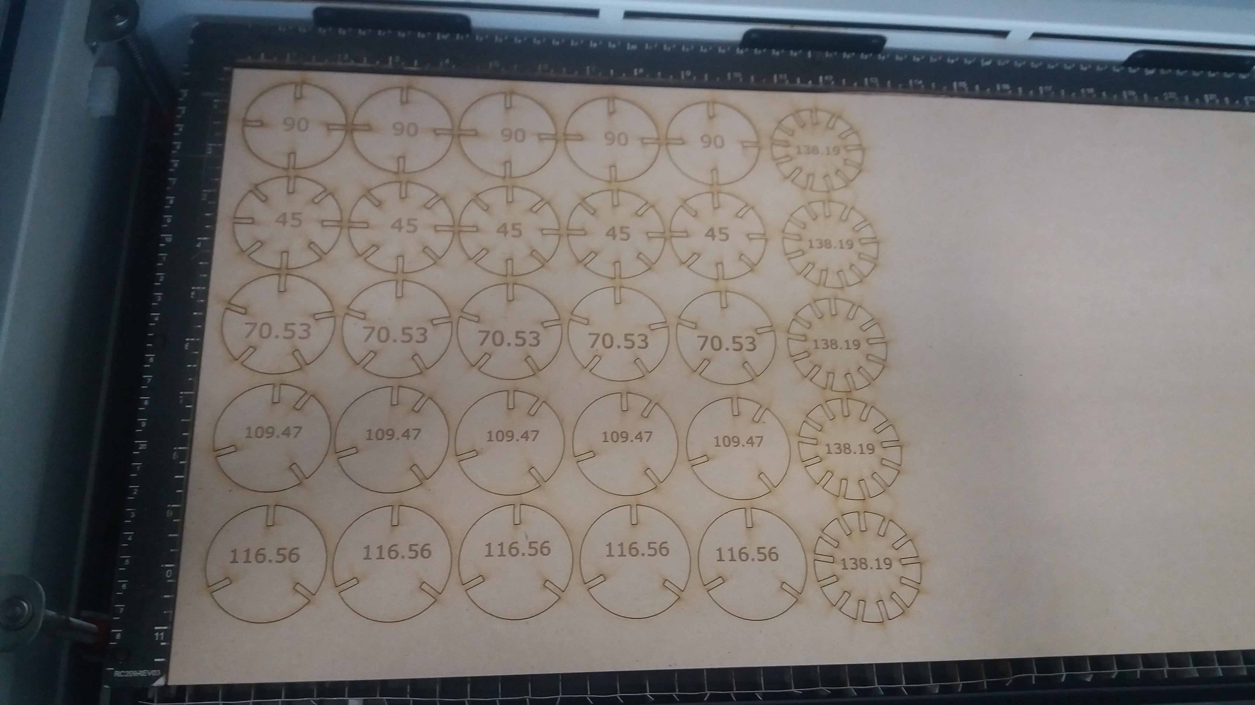
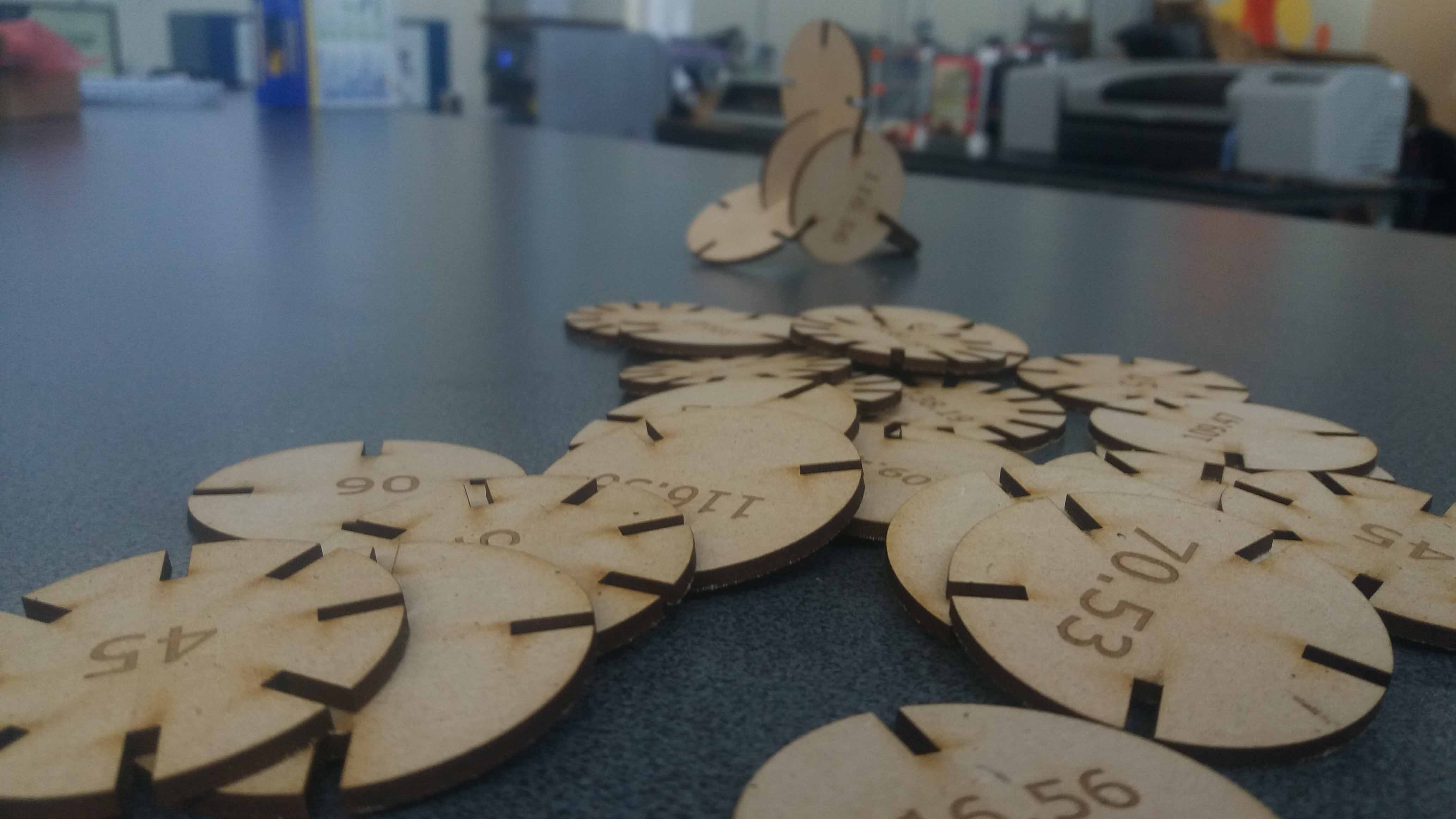
For construction, first, we use the text layer to engrave the angles of the pieces we are going to cut.
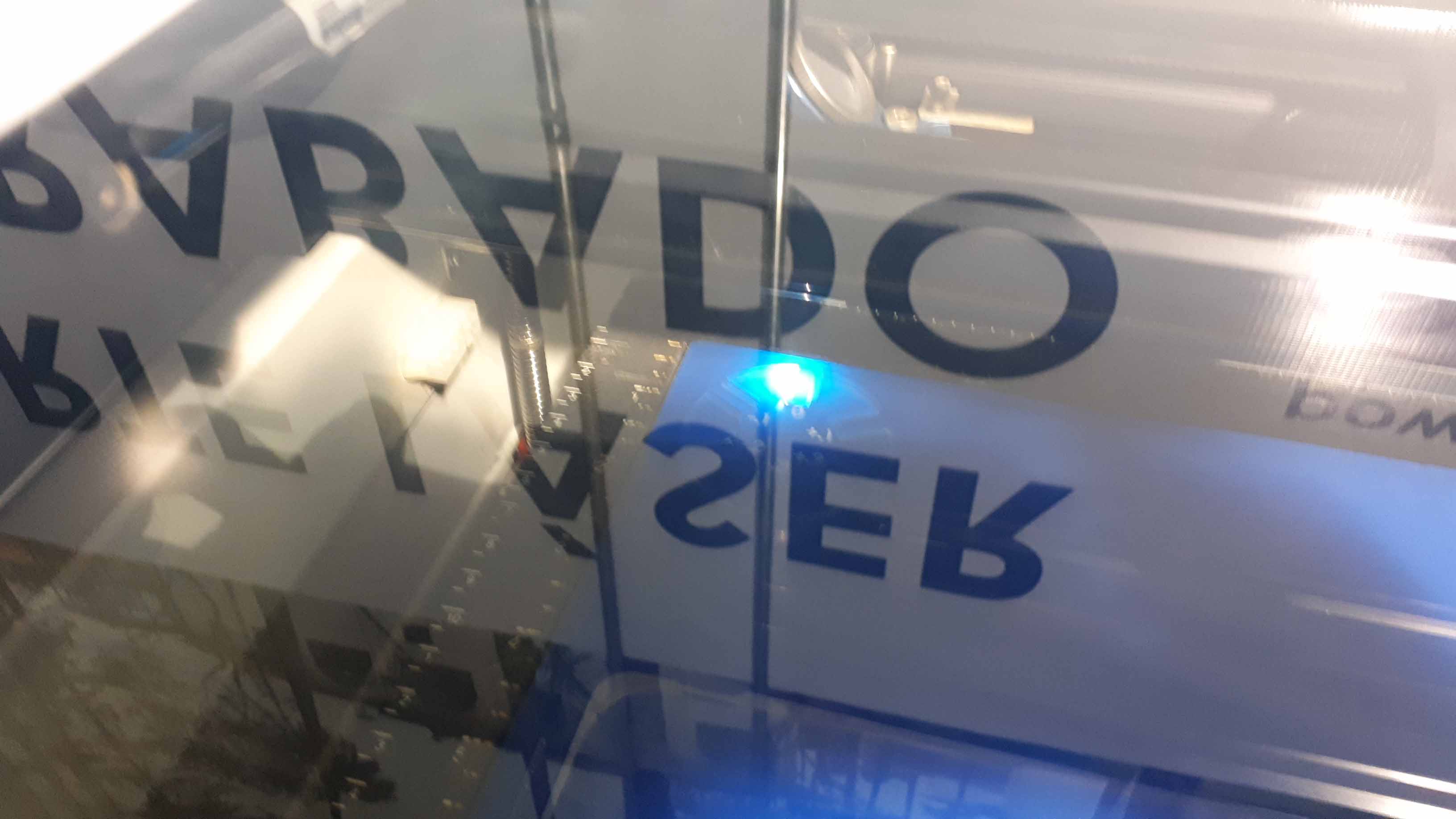
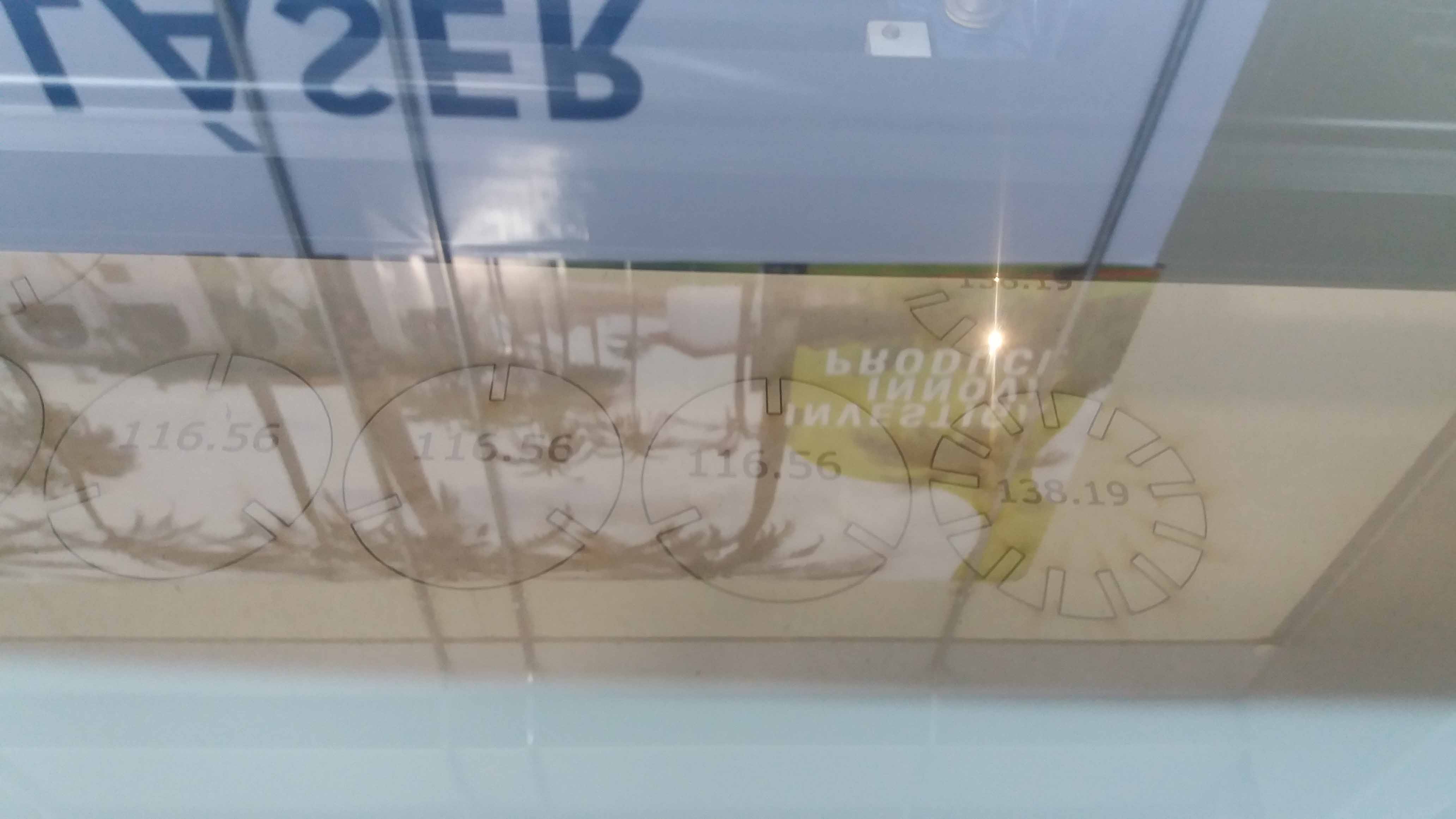
Then we proceed with the cutting layer. Here we can see it through the glass.
This is the fimal cut, from the laser inicidence side.
And here we can see it from the other side. Notice that the laser barelly comes out from the other side. This "kiss cut" is the ideal result.
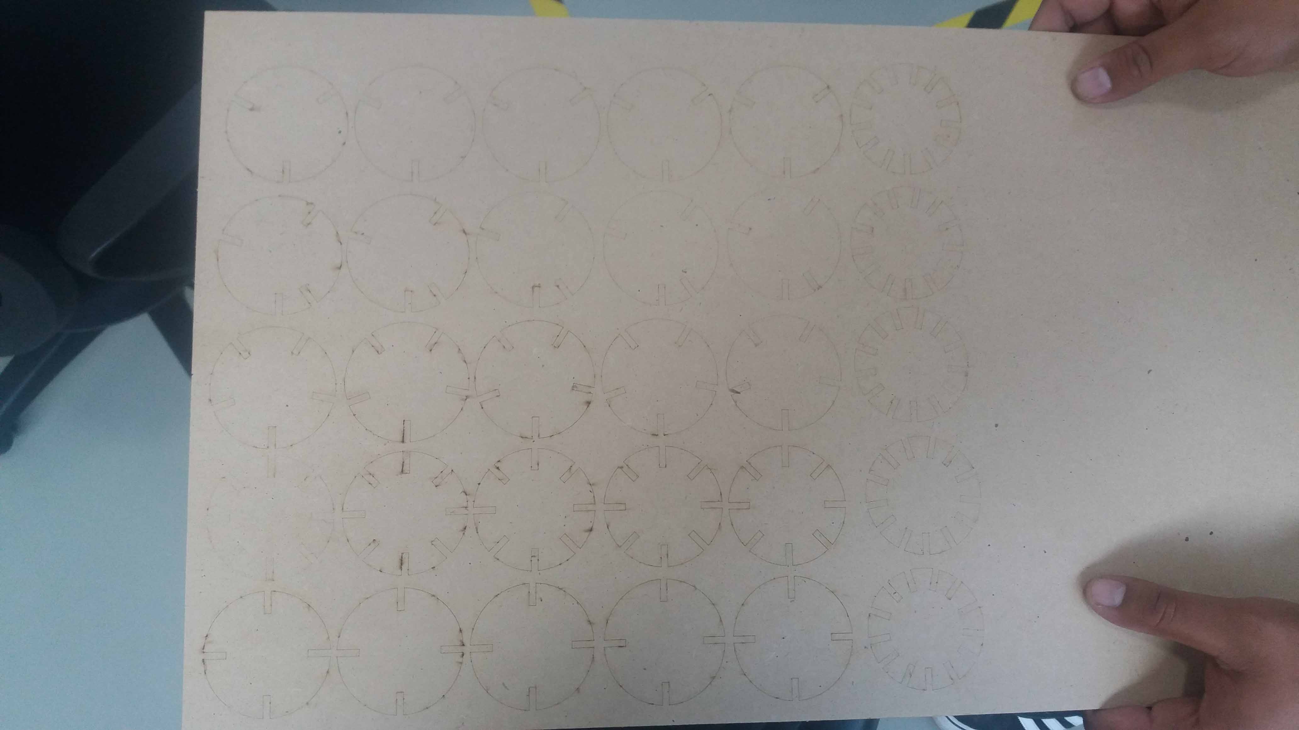
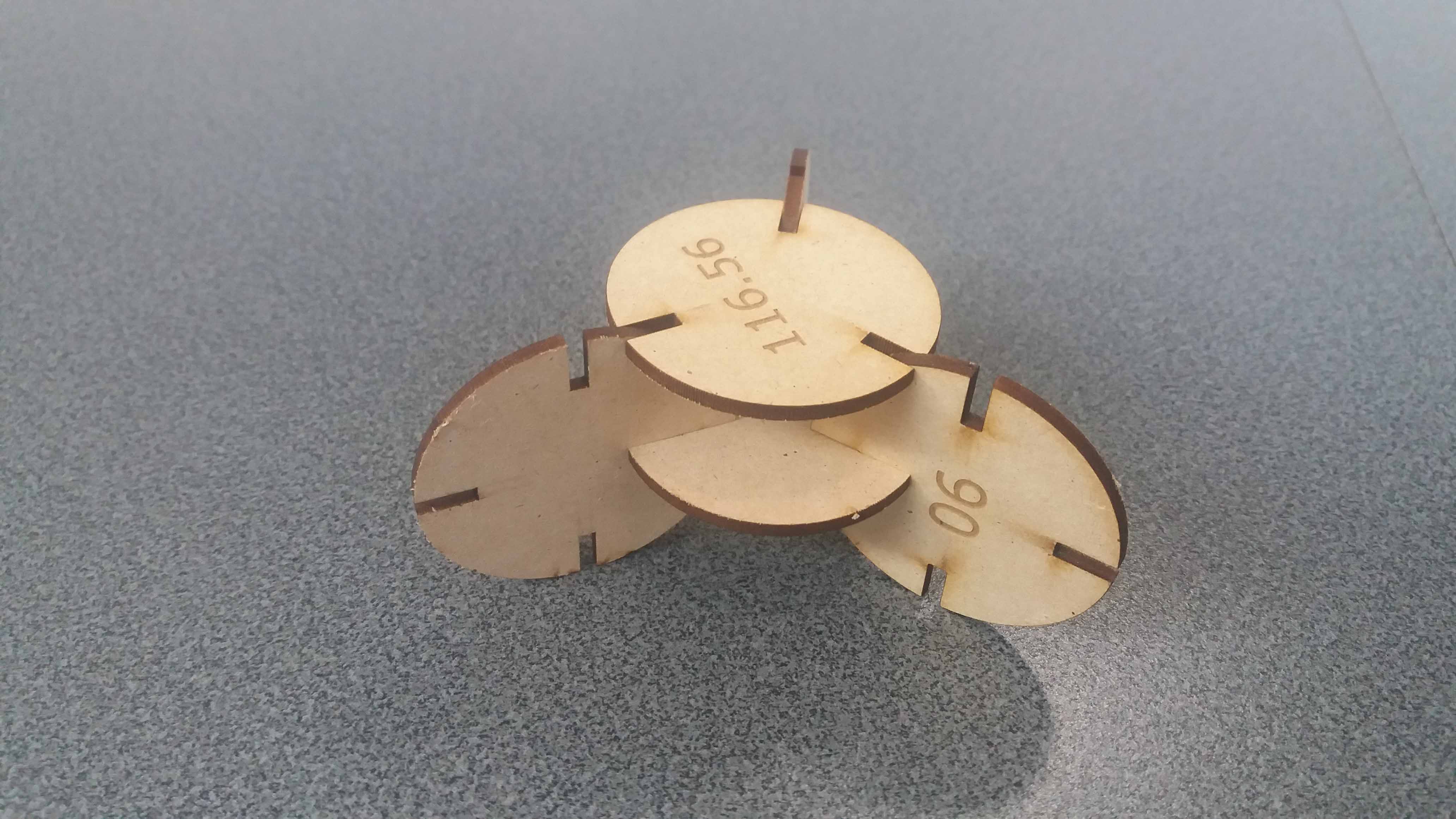
We obtain sets of pieces with different angles (taken from the pitagoric solids).
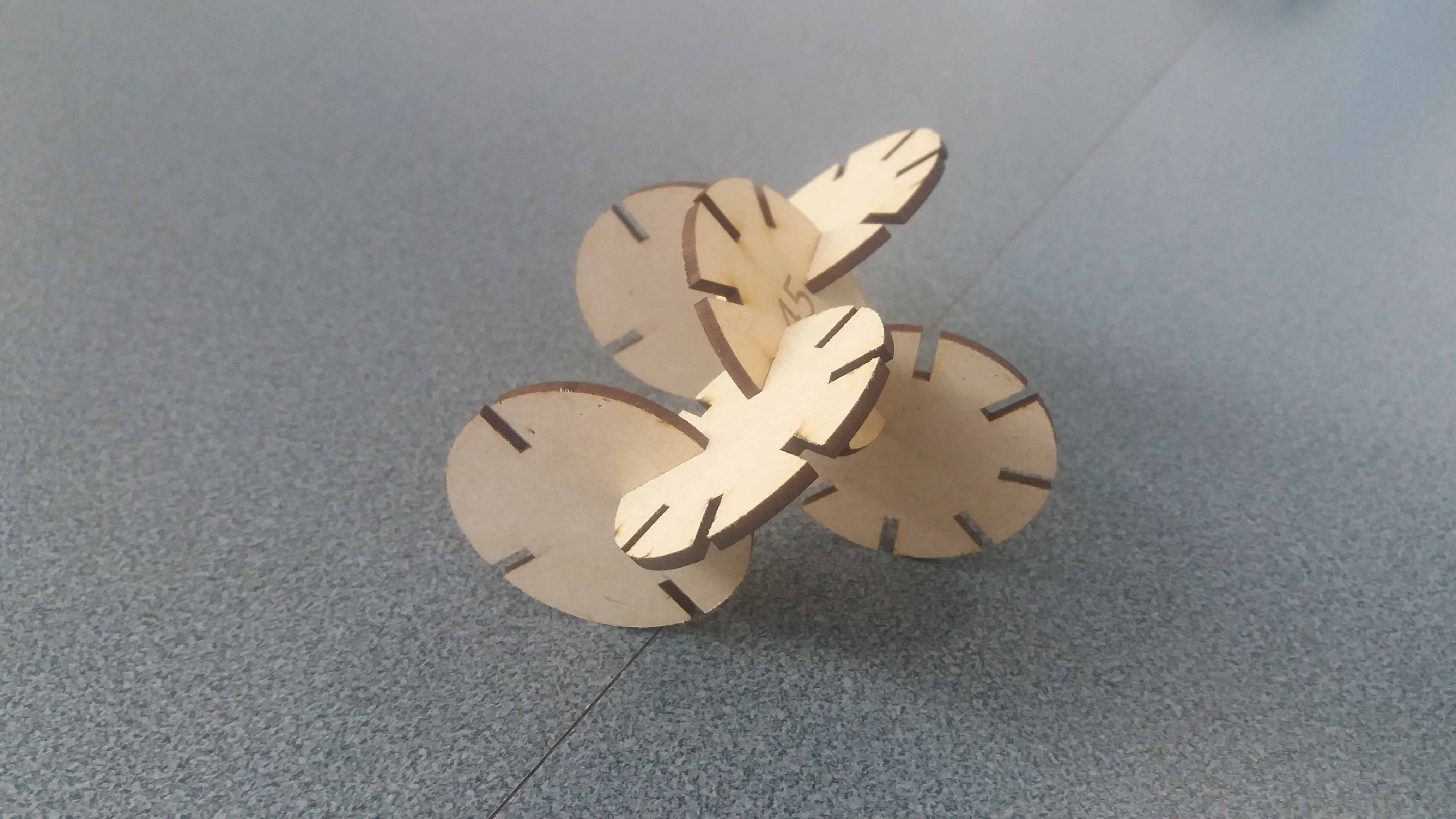
This allow us to choose between different angles of costructuction.
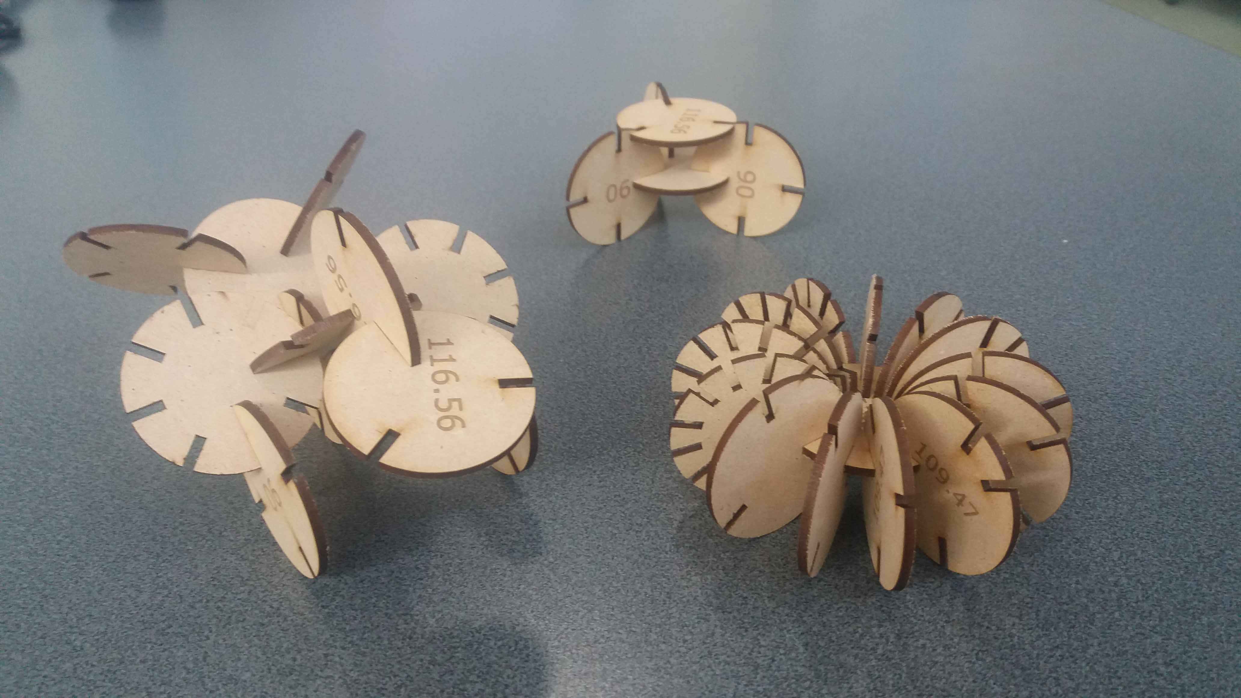
Some configurations are really structurally strong.
Here we can see some of the objects we can build.
These are the set of pieces cut in this project.
All the kit, when not assembled, occupies not much space.
There is no specific project that is focussed on this very useful tool. There are a range of ways you might utilise it throughout the programme, or your local instructor may set a specific project.
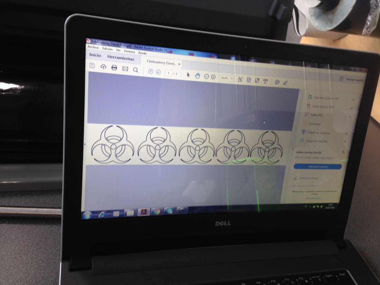
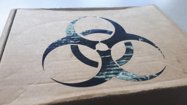
This is the first time I use vinyl cutting technology. In order to get familiar with the process, I decided to make a simple sticker, and I found something simple to transform in vector graphics. The image should have high contrast, so I searched the web for a bio-hazzard symbol. The raw file is found here.
Learning outcomes:
Identify and explain processes involved in using this machine.
Design and create the final object.
Have you:
Explained how you drew your files:
For this project I used Inkscape. This is not a parametric design program, but is very versatile for graphics editing and to transform Bitmap graphics in its vector representation. Beside that, its open source.
Bitmaps are files that represent a picture with dots (pixels). For each pixel, there is information related to its position, color and transparency. They tend to be big for high resolution, and they become pixelated if scaled to biger sizes. They are the norm in photo sharing on the net.
On the other hand, Vector graphics represent the image using vectors. The information needed for this vector is minimal, and the mathematical nature of this figures makes it possible to scale it without loosing quality.
Vectors are great for computer contolled machines. They “guide” the tool (láser, CNC, vinyl knife) in staight or curved lines without the need of new calculations to generate the paths. Usually, the time needed for this cutting reduces considerably, compared to Bitmap graphics.
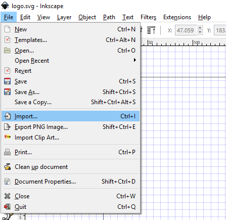
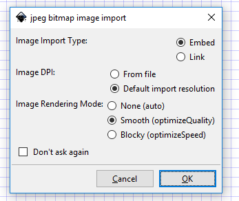
First, open Inkscape and choose import. Choose the file location, then fill the properties of import. We choose Embed (So the file is independent from the original Bitmap), default import resolution, and smooth as a rendering mode. Choose the one that fit your needs, but keep always the Embed choice.
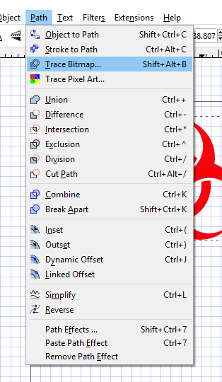
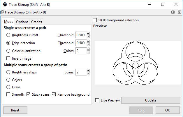
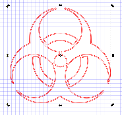
We choose Path--> Trace Bitmap. Play with the setting according to the quality of the bitmap tracing. Don't use mutliple scans. It will create undesirable paths.
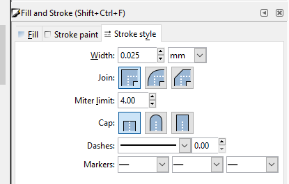
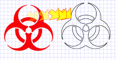
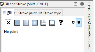
Clicing OK will create a vector version of our desing. Clic and drag to separate the two objects. Separate the parts clicking and dragging, as shown in the yellow arrows. The original Bitmap could be deleted by now. Choose the vector lines, then modify them using Fill and Stroke.
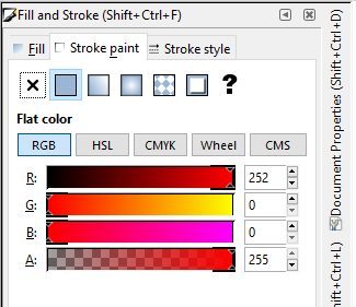
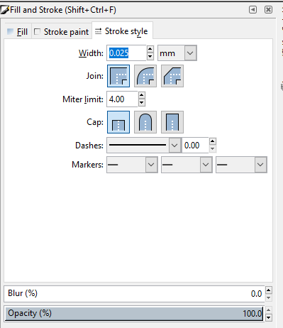
We need to set the line in solid red (RGBA, 255, 0, 0, 255), and hairline width (0.025 mm). This will tell the machine to cut the lines with this properties.
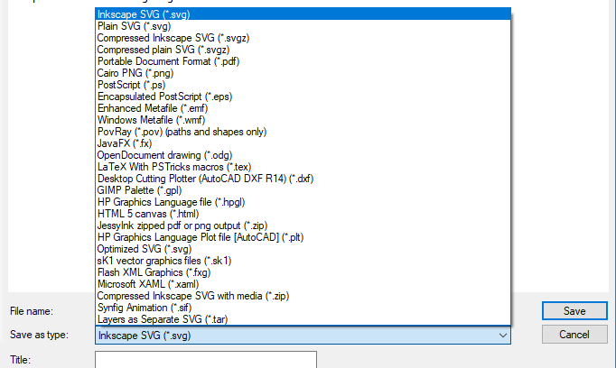
After choosing the line properties, choose save as, and save the documents in the formats suitable for cutting. In this case, they will be SVG and PDF.
Shown how you made your vinyl project
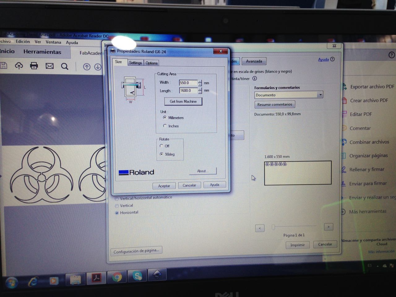
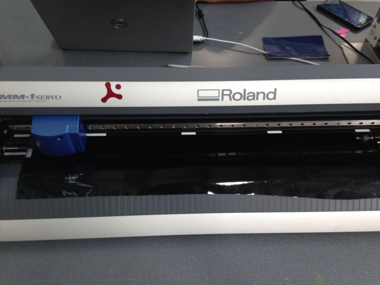
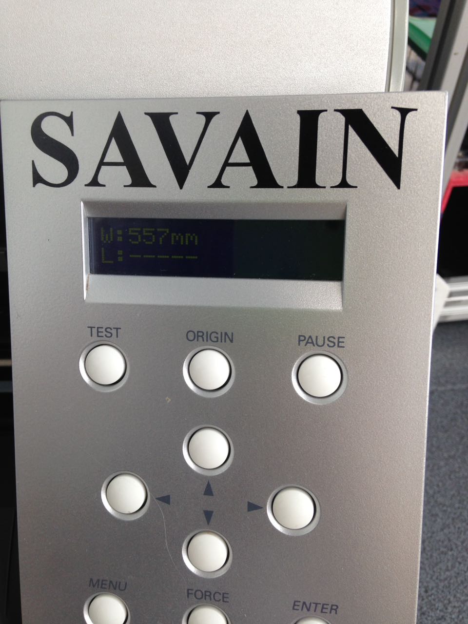
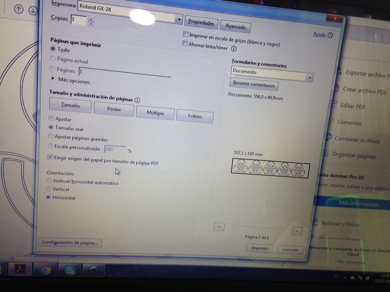
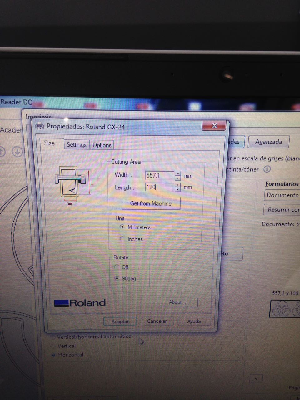
We send the job to the machine as if we were going to print a text document with a paper printer. We set the with and length.
We set the width and length in the machine console.
Check more settings. Blade rotate 90°.
Check more settings. Blade rotate 90°. Clic in the video to see the machine in action.
And here is the Heroshot. I made some of them. Personally, I don't recommend using this symbol in a trivial manner, because it represents a potencial Biohazzard, and should be only in the places that require it. It could be usefull in a DIY lab, though, where special care about the Bio samples manipulation is needed.
Included your design files and photos of your finished project in process


