Final Project
Autonomous Resource Device
Dispositivo Autónomo de Recursos (DAR)
Cubo 1_ Maceta / Cube 1_ Plant pot
Resumen / Abstract
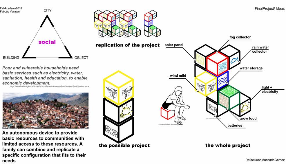
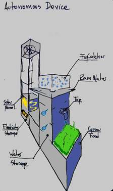
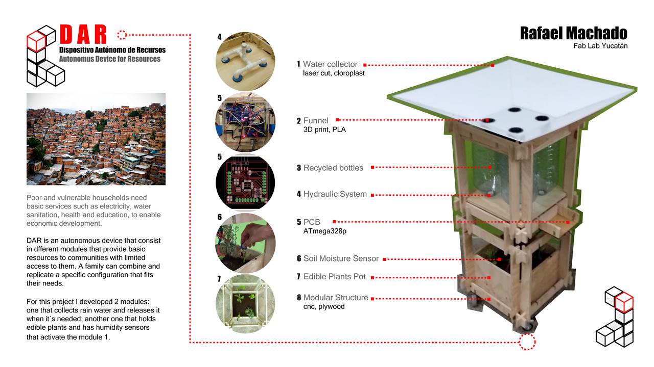
Dispositivo Autónomo de Recursos (DAR) es un aparato modular que recolecta recursos tales como energía de la luz del sol, del viento, agua de lluvia, de la neblina, almacene energía y hasta produzca alimentos a través de la siembra. La propuesta surge de la realidad de más de la mitad de la población del mundo, la cual no tiene acceso constante a recursos básicos como agua y energía. Bajo ningún motivo pretendemos que con este proyecto resuelva un gran problema tan complejo, pero al menos si contribuir a la búsqueda de alternativas desde nuestros frentes de trabajo. El dispositivo es de fácil transporte, armado y replicado, para así generar nuevas relaciones y redes de intercambio no solo energéticas. Por ahora es solo una propuesta simple, que pretendo siga evolucionando en el tiempo más allá de los compromisos académicos. La intención es que casi cualquier persona pueda armarlo, mejorarlo y replicarlo.
Autonomous Resource Device (DAR) is a modular apparatus that collects resources such as sunlight, wind, rainwater, energy, and even produces food through planting. The proposal arises from the reality of more than half of the world's population, which does not have constant access to basic resources such as water and energy. Under no circumstances do we intend to solve such a complex problem with this project, but at least contribute to the research for alternatives from our work fronts. The device is easy to transport, assembled and replicable, to generate new relationships and networks of exchange not only of energy. For now it is just a simple proposal, which I intend to continue to evolve over time beyond academic commitments. The intention is that almost anyone can put it together, improve it and replicate it.
Palabras claves / Key Words
Recolección de recursos, dispositivo, acceso a Recursos, energías renovables, sustentabilidad
Collection of resources, device, access to resources, renewable energies, sustainability
Previo / Previous
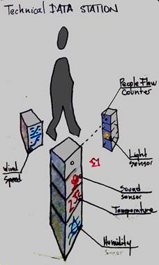
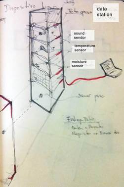
Además de esta idea de DAR, paralelamente al inicio se manejaron otras dos ideas. Una, otro dispositivo que mediría condiciones atmosféricas, geográficas y situacionales de un lugar en un momento determinado; la Estación de Datos Técnicos.
In addition to this idea of DAR, at the same time in the beginning, two other ideas were handled. The first one was another device that was going to measure atmospheric, geographic and situational conditions of any place at a given time; that was the Technical Data Station.
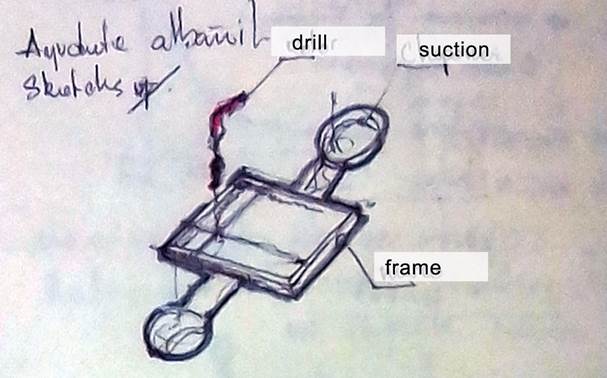
La otra idea fue el Ayudante de Albañil, el cual era una especie de CNC portátil que tallaba siguiendo la marca hecha previamente por un lápiz
The other idea was the Mason's Assistant, which was a kind of portable CNC that is supposed to carved following the mark previously made by a pencil
Introducción / Introduction
|
1. image created in the first week assigment
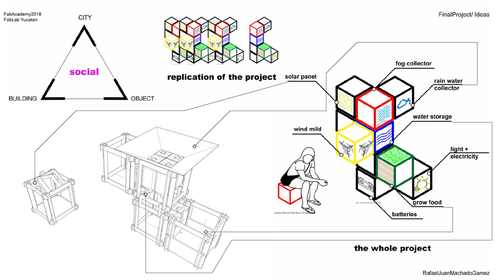
El proyecto es un objeto independiente que se añade a las viviendas construidas en los barrios y que al replicarse masivamente puede tener una repercusión en la ciudad; transversalmente a su escala está dentro de la dimensión social. En la medida en que los barrios tengan mejor acceso a recursos, se podrán atender otras necesidades por ahora secundarias pero igual de importantes. Por ahora solo se desarrollaran pocas partes del proyecto, que ha ido avanzando ya que he ido complementando las tareas a él. El dispositivo debe ser ligero, armable y modular, para así poder llegar a las áreas de difícil acceso de trasporte público.
Ahora comparando lo que voy a hacer como proyecto final con la primera idea que tuve, ambas son bastante similares y el dispositivo cumplirá varias de las funciones que propuse desde el inicio. Otras serán cubiertas en el futuro en la continuación del proyecto.
The project is an independent object that is added to the houses built in the slums and that by them replicating massively can have an impact on the city; transversally to its scale is within the social dimension. When the slums have better access to resources, other needs that are currently secondary but equally important may be addressed. For now only few parts of the project will be developed, which I have been developing integrating the assignments to it. The device must be light, assemblable and modular, in order to reach the areas of difficult access for public transport.
Now comparing what I'm going to do as a final project with the first idea I had, both are quite similar and the device will fulfill several of the functions that I proposed from the beginning. Other functions will be covered in the future in the continuation of the project.
El Proceso / the Process
La mayoría de las asignaciones del Fab Academy fueron enfocadas desde el inicio en el proyecto final.
Most of the Fab Academy assignments were focused from the beginning on the final project.
En una de las primeras asignaciones aproveché la oportunidad para profundizar mis conocimientos en Photoshop y lograr un estilo de comic, mezclando un dibujo a mano con técnicas de edición de imágenes. Pero además del aprendizaje técnico, fue también una oportunidad para definir mejor el proyecto. Y es así como el sistema empieza a tomar forma entendiendo qué funciones puede tener y cómo. Identifiqué que podría tener: Molino de viento para energía eólica, paneles solares, baterías para el almacenaje de la energía, recolección de agua de lluvia, almacenaje para agua, atrapa niebla y espacio para siembra de alimentos.
In one of the first assignments I took the opportunity to deepen my knowledge in Photoshop and achieve a comic style, mixing a hand drawing with image editing techniques. But in addition to technical learning, it was also an opportunity to better define the project. And this is how the system begins to take shape by understanding what functions it can have and how. I identified what it could have: Windmill for wind energy, solar panels, batteries for energy storage, rainwater collection, water storage, mist trap and space for planting food.
Estructura / Structure
Las primeras opciones no eran tan eficientes porque no eran estables y representaban mucho gasto de material ya que toda la superficie de sus caras tenía que ser de madera.
The first options were not so efficient because they were not stable and they represented a lot of material expenditure since all the surface of their faces had to be made of wood.
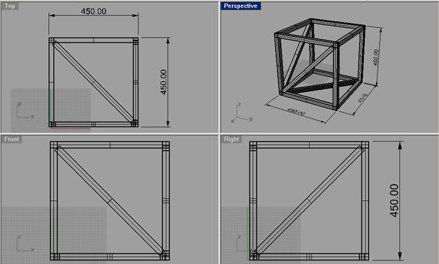
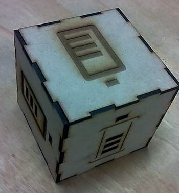
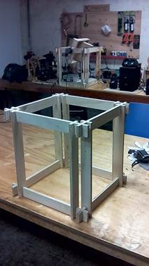
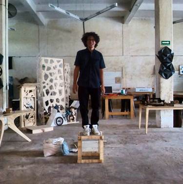
Diseñé un módulo en forma de cubo que se puede apilar, y que tiene la medida ideal para poder levantarlo o que pueda hasta server de mobiliario. Además sus partes son pequeñas para cortarse en el router. Lo más importante es que sea estructuralmente estable, de allí las diagonales que evitan desplazamientos laterales.
I designed a module in the form of a cube that can be stacked, and that has the ideal size to be able to be lifted or that can even serve as furniture. In addition, its parts are small to be cut in the router in small spare wood that remains in the lab. The most important thing is that it is structurally stable, hence the diagonals that prevent lateral displacements.
CNC
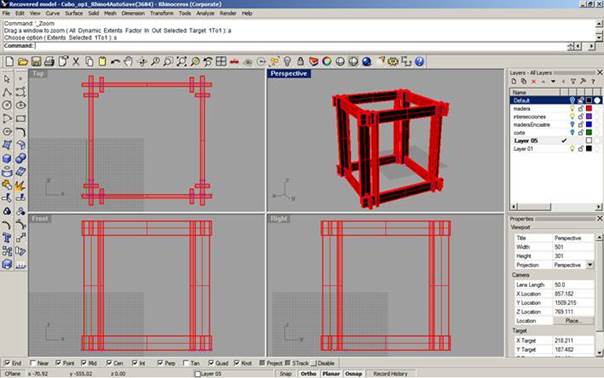
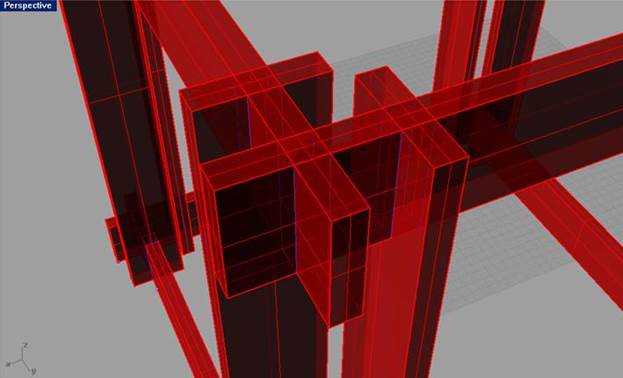
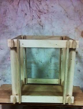
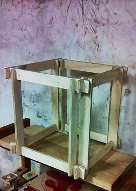
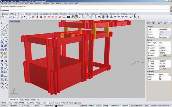
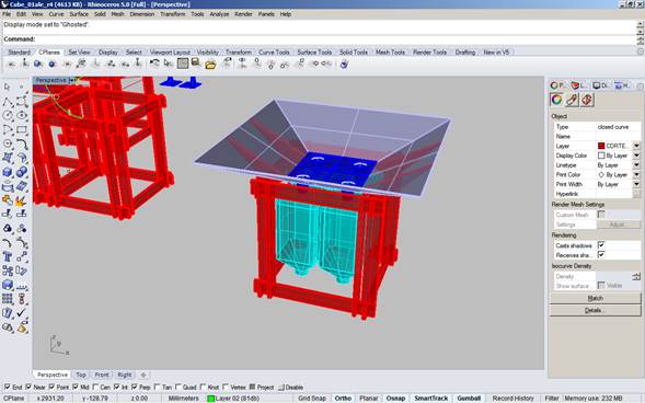
A partir del cubo empecé a profundizar en su diseño y se me ocurrió ensamblarlo en partes que se cortaban de manera separada para que el dispositivo se pudiera transportar desarmado hasta el lugar donde luego se armaría para su funcionamiento. Es así como lo diseñé en Rhinoceros desde su forma hasta los cortes que necesitaba para hacerlo.
From the cube I began to deepen its design and it occurred to me to assemble it in parts that were cut separately so that the device could be transported unarmed to the place where it would later be assembled for its operation. This is how I designed it in Rhinoceros from its form to the cuts I needed to do it.
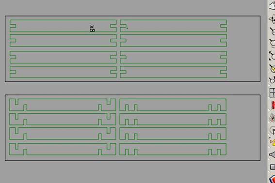
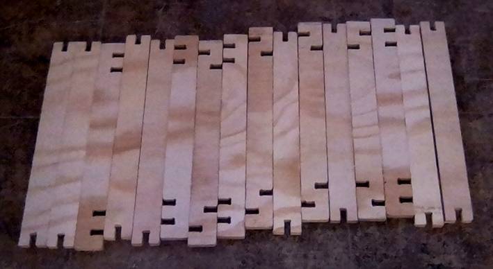
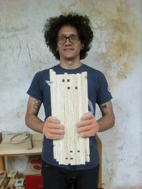
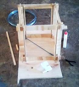
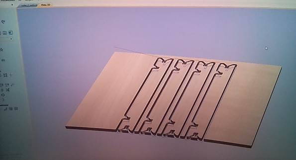
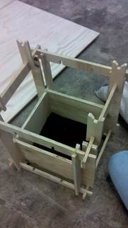
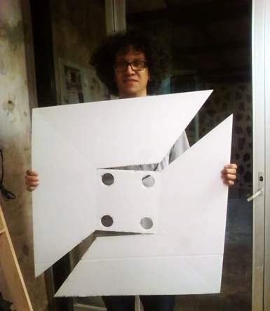
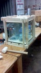
Estas son las piezas necesarias para armar un cubo. Desarmadas pueden ser transportadas con mayor facilidad para el lugar donde se vaya instalar el dispositivo. Luego se arma el cubo y pesa unos 2,5 kg.
These are the pieces needed to build a cube. Disarmed can be transported more easily to the place where the device is installed. Then, after the cube is assembled its weigh is less than 2,5 Kg.
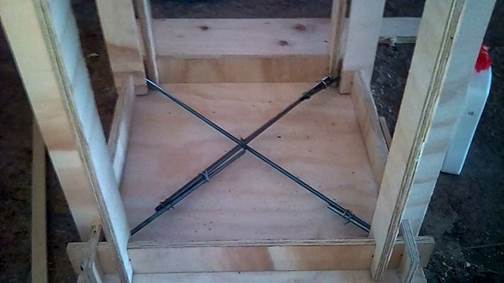
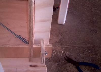
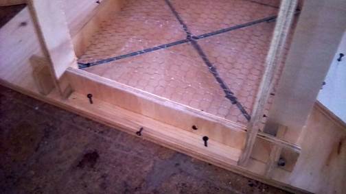
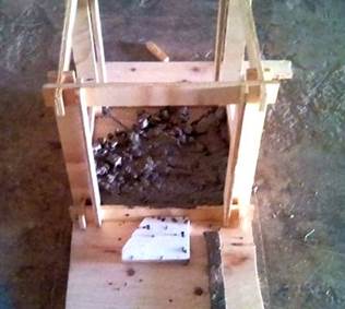
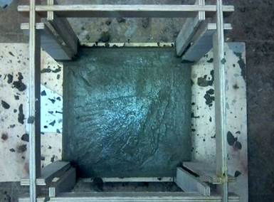
Una de las opciones que probé en el proceso, ya que si esta pieza está a la interperie, es que tenga el suficiente peso para que no salga volando en una ventisca. Para la asignación de Molding and Casting probé vaciar la cara inferior en concreto para darle rigidez y peso suficiente. Para que el concreto no se partiera por las fuerzas de tracción y corte, coloque barras roscadas diagonalmente que junto a una malla de gallinero y tornillos que atravesaban la madera le darían la fuerza y cohesión suficiente. Reciclé pedazos de barras que encontré en el Fab Lab. Estas eran solapadas y unidas con alambre para generar una sola pieza que trabaje a tracción. Luego se mezcló, vació, emparejó y dejo secar el concreto hasta su endurecimiento 24 horas luego
One of the options that I tried in the process, because this piece was going to be outside, it should have enough weight so it does not fly out in a blizzard. For the assignment of Molding and Casting I tried to fill the lower face in concrete to give it rigidity and sufficient weight. I placed diagonal rods that together with chicken net and screws trough the wood, would give the strength and sufficient cohesion. I recycled pieces of rod from the Fab Lab, and joint the pieces with wire. In the future the reinforcement of the concrete could be made in the same way, recycling iron, but being careful that the pieces are joined together correctly. Afterwards the concrete was mixed, poured, leveled and let dry till the concrete was hard enough.
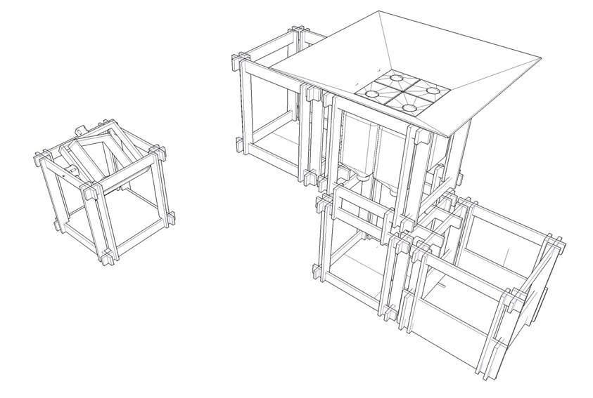
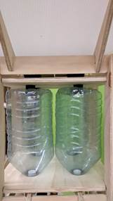
Diseñe casi todo en Rhinoceros replicando el primer cubo y adaptándolo a nuevas necesidades como el contenedor de agua, el contenedor de plantas y el recolector de agua. Estas piezas serán cortadas en el router en madera triplay de 12mm. Para almacenar el agua reciclaré recipientes para agua de 5 litros cada uno. Logrando captar 20 litros por cubo contendor. Los cubos estarán encajados entre si formando un sola pieza todos juntos
Designed almost everything in Rhinoceros by replicating the first cube and adapting it to new needs like the water container, the plant container and the water collector. These pieces will be cut in the router in 12mm plywood. To store the water I will recycle water containers of 5 liters each. Achieving 20 liters per container cube. The modules will designed in press fit and they all together will be one piece.
Cubo 1_ Maceta / Cube 1_ Plant pot
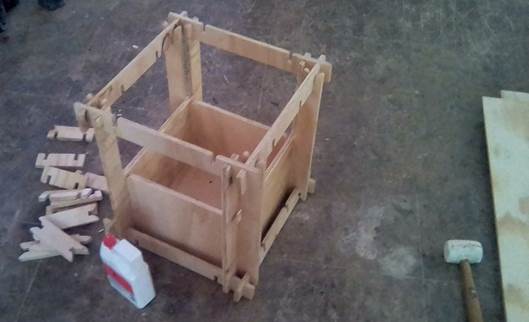
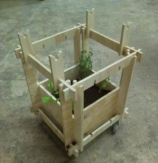
El primer módulo que desarrollaré es el que llevará las plantas. Tendrá tierra en su interior de aproximadamente unos 20 cm de profundidad, según me recomendó un colectivo que se dedica a la siembra y difusión de técnicas para huertos urbanos llamado Milpa.
Rediseñe las piezas para que se adaptara al nueva necesidad de un matero. Y con ángulos en las uniones para que las piezas se armen más fácilmente. Lo ensamblé y coloqué ruedas para que fuera fácil de transportar, ya que posiblemente con la tierra y el agua se haría pesado. Luego lo rellené de tierra y planté 4 plantas de espinaca y una de lavanda para que sirviera de repelente natural.

Corte Láser / Laser Cutting
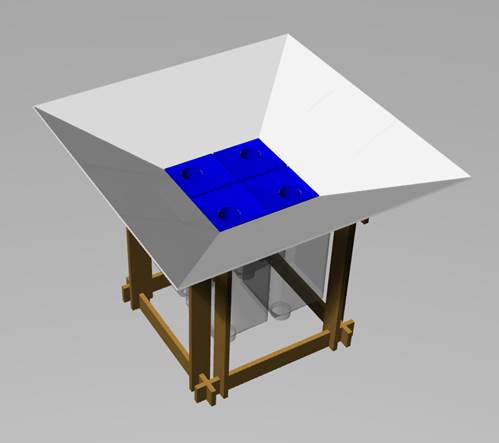
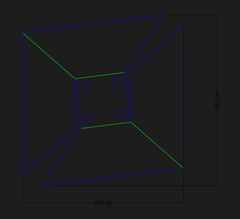
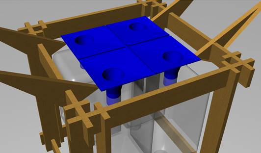
El segundo cubo lleva un colector de agua que se trata de una pirámide invertida truncada. El material es cloroplast de 4mm. Lleva 4 perforaciones por donde el agua recolectada baja a los recipientes plásticos. En la tarea de “3D modeling” se puede observar el proceso de modelado y creación del archivo de corte (.dxf).
Impresión 3D / 3D printing
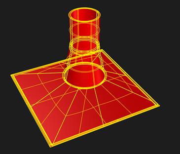
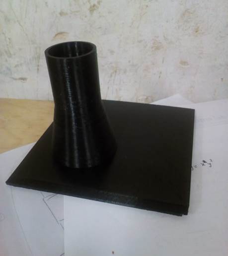
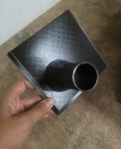
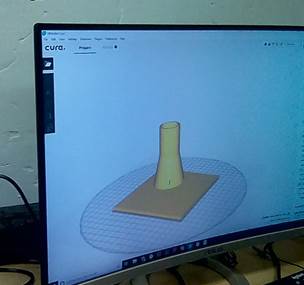
El colector de agua necesitaba embudos que llevaran el agua a los recipientes. Estos embudos fueron modelados en Rhinoceros y exportados en formato .STL
Después arrastramos el modelo en STL a Cura, para generar el Codigo G. Elegi el perfil Low Quality para que no tardara tanto y aun así cada pieza tarde 8 horas. Estos son las configuraciones que use: Grosor de capa 0.15mm, Espesor de pared 1.0mm, 30% de relleno. Para el PLA la temperatura del extrusor es de 200 grados y la de la cama 60 grados.
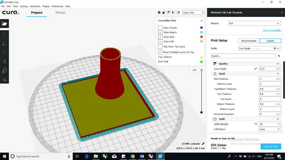
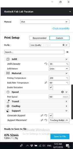
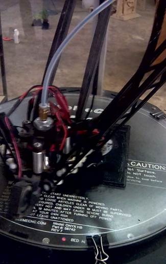
Los 4 embudos se imprimieron en 3D en la impresora Rostock Max Delta, y utilizamos PLA color negro.
Electrónica / Electronics
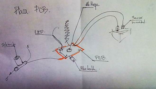
El boceto de lo que deseo hacer
The sketch of what I want to do
RafDuino
Decidí para la placa hacer un FabDuino o Rafduino para poder practicar y testear toda la programación y electrónica. La prioridad es hacer que los sensores de humedad abran o cierren la válvula solenoide. Si me da tiempo, haré que el bombillo Led encienda en caso de hacer falta agua y colocaré una tarjeta de bluetooh para mandar un mensaje a una aplicación donde aparezca los datos de humedad y si la válvula está cerrada o abierta. Por eso seleccioné una AtMega en vez de una AtTiny. 1. Por el número de pines que me dejarán conectar otras cosas en el futuro. 2, por la capacidad del microprocesador en memoria y manejo de varios componentes al mismo tiempo. 3. Facilidad de encontrar librerías
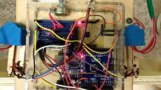
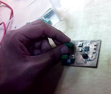
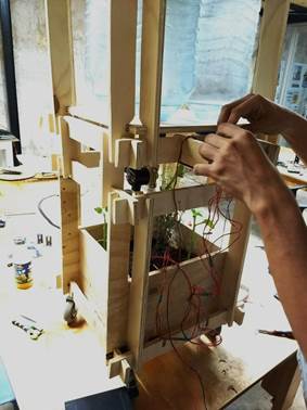
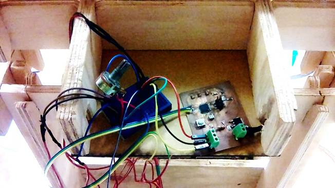
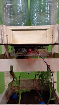
Puse pines para poder conectar y desconectar fácilmente con jumpers. Conecté los sensores a los pines analógicos. Extra, tuve que hacer un protoboard con un mosfet para poder controlar la válvula solenoide. Al momento de alimentar con corriente el circuito me vi en ciertas dificultades. El solenoide lo alimenté con una fuente de poder que diera 12v. Y para la placa, utilicé un Arduino, pero solo como transformador de corriente, ya que conecté una pila de 9voltios al arduino que a solo alimentaba a fabduino con el voltaje de 5v que requería. Todo lo metí en una caja de acrílico para proteger los circuitos y que fueran visibles ya que la placa prendía y apagaba su Led también dependiendo de las condiciones de humedad de la tierra. Esta caja la coloque bajo una pieza para protegerla aún más, ya que estaría expuesta a la intemperie.
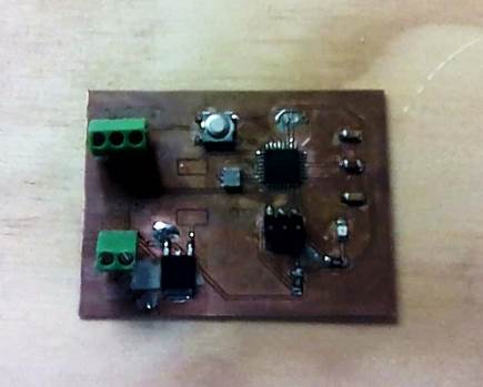
Luego de hacer y probar la electrónica, el sistema, y el montaje de todos los componentes con un RafDuino con el que venía trabajando para pasadas asignaciones, decidí hacer mi propia placa basada en todo ese conocimiento previo y específico para la tarea que realizará en mi proyecto final. Por ejemplo centralizar las resistencias y componentes extras en la misma placa, así como alimentar los componentes externos a través de la placa.
I decided for the PCB to do a FabDuino or RafDuino to be able to practice and test the programming and electronics. The priority is to have the humidity sensors open or close the solenoid valve. If I have time, I will make the Led turn on if water is needed and I will place a Bluetooth card to send a message to an application where the humidity data appears, also if the valve is closed or open. If I have time or in the future, the same board should control del Solar tracker developed previously, a led lamp, control water level, etc. That’s why I selected the AtMega instead of Attiny. 1. The numbers of pins will allow me to connect more devices to the same board in the future. 2. The capacity of the microprocessor in memory and handling other components at the same time. 3. Easier to find libraries to program
I put pins all around the board to make it easy to connect and disconnect with jumpers. I connected the sensors to the analog pins. Extra, I had to make a breadboard with a mosfet to be able to control the solenoid valve. At the moment of powering the circuit I saw myself in certain difficulties. The solenoid I fed it with a power source that would give 12v. And for the board, I used an Arduino, but only as a current transformer, I connected a 9 volt battery to the Arduino that only fed fabduino with the 5v voltage that it required. I put everything in an acrylic box to protect the circuits and to be visible since the plate turned on and off its LED also depending on the humidity conditions of the soil. This box is placed under a piece to protect it even more, since it would be exposed to the elements.
After doing and testing the electronics, the system, and the assembly of all the components with a RafDuino with which I had been working for the past assignments, I decided to make my own PCB based on all that prior knowledge and specific to the task that will be done in my final project. For example, centralize the resistances and extra components in the same board, as well as to feed the external components through the plate.
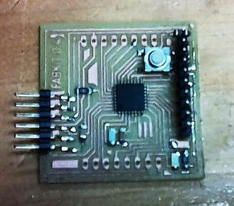
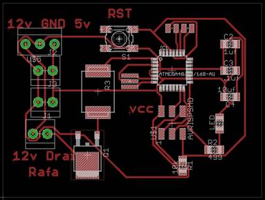
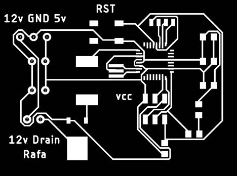
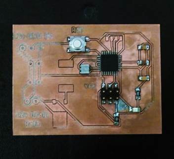
PCB Final
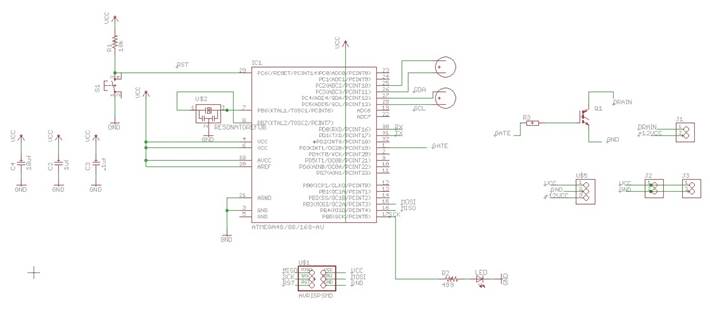
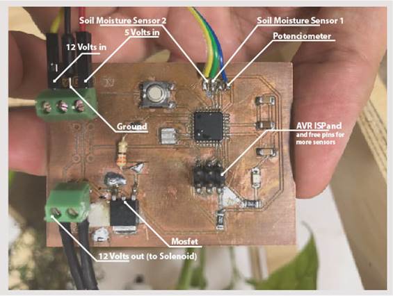
Luego de la experiencia adquirida con el FabDuino, procedí a diseñar la nueva placa. Otra vez usaría el Microprocesador AtMega por las mismas razones expuestas anteriormente. Aunque para este prototipo no requiera una placa de ese calibre, mi intención de continuar el proyecto es real. Y necesitaré una placa con mayor capacidad de procesamiento, memoria y pines para conectar más sensores de diferente tipo en el futuro. Por ahora solo necesitaré algunos que dejé libres, pero en caso de necesitar más podré usar los pines del AVRISP que es por donde programo la placa.
Los componentes pasivos:
· 2 capacitores no polarizados de 1uf
· 1 capacitor no polarizado de 10uf
· 1 resistencia de 10k
· 1 resonador de 20mhz
Los components activos:
· Botón de reset
· Mosfet
· 1 resistencia de 499 Ohms
· Resistencia
· Led
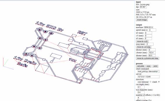
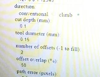
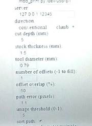
Mi amigo Jesús me recomendó cambiar algunos parámetros para cortar mejor. Ya que en la primer intento no se cortaron algunos trazos y quedaban unidos. Así que redujimos la cantidad de offsets y modificamos la profundidad de corte. Luego cuando corté la placa también modificamos algunos parámetros porque estas placas son más delgadas que lo común y para no cortar tanto la cama redujimos la profundidad de corte.
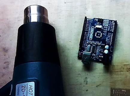
Una vez cortada la placa, procedí a soldar sus componentes. En el Lab no había AtMega, así que reciclé una de un Arduino dañado. Aprendí la técnica de desoldar y soldar con la pistola de calor. Hay que colocarla a 500°C y dejarla muy cerca del arduino para que el estaño se afloje y se libere la placa, tomándola con una pinza. Luego se coloca el micro procesador sobre la PCB que corté y como trae estaño aun adherido a sus patas al colocarle nuevamente la pistola muy cerca, el estaño se adhiere a los traces. (Previamente hay que colocar pasta de soldar sobre la placa para que ayude a la adherencia del estaño a los traces)
Esta placa la rediseñe y redibujé en Eagle. Luego produje los códigos G desde Fabmodules para cortarlos luego con la Rolland SMR-20
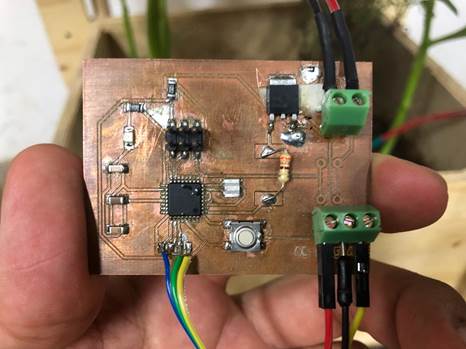
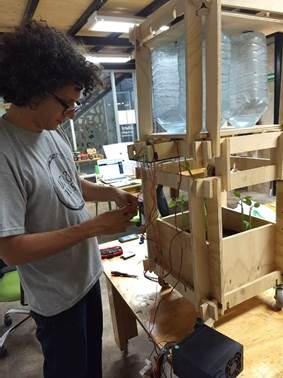
Una vez ya lista la placa, la instalé en mi protoripo. Primero conectando todo para verificar que el sistema funcionaba bien. Luego introduje la electrónica dentro de su caja de acrílico diseñada para protegerla con aberturas especiales para el potenciómetro y salidas y entradas de cables de VCC, GND, y señales.
After the experience gained with the FabDuino, I proceeded to design the new PCB. Again, I would use the AtMega Microprocessor for the same reasons discussed above. Although for this prototype could use a smaller microprocessor like the Attiny, my intention to continue the project is real. And I'll need a board with more processing power, memory and pins to connect more sensors of different types in the future. For now I will only need some pins that I left free, but in case I need more I can use the AVRISP pins that is where I program the board.
The passive components:
• 2 non-polar capacitors of 1uf
• 1 10uf unpolarized capacitor
• 1 resistance of 10k
• 1 resonator of 20mhz
The active components:
• Reset button
• Mosfet
• 1 resistance of 499 Ohms
• Resistance
• Led
My friend Jesus recommended me to change some parameters to cut better. In the first attempt some traces were not cut and they were united. So we reduced the amount of offsets and modified the depth of cut. Then when I cut the PCB we also modified some parameters because these PCB´s are thinner than usual and we reduced the depth, so we don’t cut the bed
Once the PCB was cut, I proceeded to weld its components. In the Lab there was no AtMega, so I recycled one from a damaged Arduino. I learned the technique of unsoldering and welding with a heat gun. It should be placed at 500 ° C and left very close to the arduino so that the tin loosens and the plate is released, taking it with a clamp. Then the microprocessor is placed on the PCB that I cut and as it brings tin still attached to its legs, when placing the gun again very close, the tin adheres to the traces. (Previously it is necessary to place solder paste on the plate to help the adherence of the tin to the traces)
This Fabduino was redesigned and redraw in Eagle. I produced with the Fabmodules the G codes to cut the plate with the Rolland SMR-20
Once the plate is ready, I installed it on my prototype. First connecting everything to verify that the system worked well. Then introduced the electronics inside its acrylic case designed to protect it with special openings for the potentiometer and outputs, inputs of cables (VCC, GND, and signals).
La lista de componentes / List of components
|
Part |
Value |
Device |
Package |
Description |
DIGIKEY |
QUANTITY |
|
C1 |
.1uf |
C-EUC1206 |
C1206 |
CAPACITOR, European symbol |
399-4674-1-ND |
1 |
|
C2 |
1uf |
UNPOLARIZED_CAPACITOR1206 |
1206 |
unpolarized_capacitor |
445-1423-1-ND |
1 |
|
C3 |
.1uf |
UNPOLARIZED_CAPACITOR1206 |
1206 |
unpolarized_capacitor |
399-4674-1-ND |
1 |
|
C4 |
10uf |
UNPOLARIZED_CAPACITOR1206 |
1206 |
unpolarized_capacitor |
587-1352-1-ND |
1 |
|
IC1 |
ATMEGA48/88/168-AU |
ATMEGA48/88/168-AU |
TQFP32-08 |
ATMEGA328P-AU-ND |
1 |
|
|
JP1 |
M06SMD |
1X06-SMD |
Header 6 |
SAM1043-06-ND |
1 |
|
|
LED |
LED1206 |
1206 |
LED YELLOW ORANGE CLEAR 1206 SMD |
160-1403-1-ND |
1 |
|
|
R1 |
10k |
RESISTOR1206 |
1206 |
311-10.0KFRCT-ND |
1 |
|
|
R2 |
499 |
RESISTOR1206 |
1206 |
311-499FRCT-ND |
1 |
|
|
S1 |
6MM_SWITCH6MM_SWITCH |
6MM_SWITCH |
OMRON SWITCH |
SW262CT-ND |
1 |
|
|
SV1 |
MA08-1 |
MA08-1 |
PIN HEADER |
S9016E-10-ND |
1 |
|
|
SV2 |
MA08-1 |
MA08-1 |
PIN HEADER |
ED6508-ND |
1 |
|
|
SV4 |
MA08-1 |
MA08-1 |
PIN HEADER |
ED6508-ND |
1 |
|
|
U$2 |
RESONATOREFOB |
RESONATOREFOB |
EFOBM |
535-10004-1-ND |
1 |
Programación / Programming
Decidí usar el lenguaje de Arduino porque me parecía el más fácil para mí y ya estoy familiarizado con él. Además que de manera intuitiva puedo ir complejizando el código añadiendo más elemento y sensores. La diferencia es que no usé una placa de Arduino sino un FabDuino hecho por mí al cual le cargué el mismo código que diseñe y probé
I decided to use Arduino's language because it seemed the easiest for me and I'm already familiar with it. In addition, I can intuitively make the code more complex by adding more elements and sensors. The difference is that I did not use an Arduino board but a FabDuino made by me where I loaded code that I designed and tested
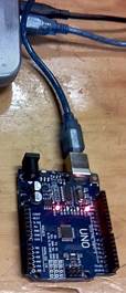
Conectar el Arduino al computador.
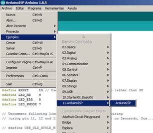
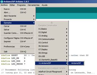
Abrir la interfaz de Arduino IDE en: Archivos/ Ejemplos/ 11.ArduinoISP/ ArduinoISP
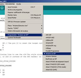
Seleccionar el Programador: Arduino as ISP, sino dará error al subir el código
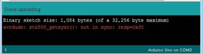
Subir al Arduino ese código (chequear que estás en el puerto correcto)
Connect the Arduino to the computer
Open the Arduino IDE interface in: Files / Examples / 11.ArduinoISP / ArduinoISP
Select the Programmer: Arduino as ISP, otherwise it will fail uploading the code
Upload that code to the Arduino (check that you are in the correct port)
Me daba el mismo error. Nuevamente Jesús me
dijo que como el Arduino que estaba usando es chino, necesitaba descargar un
driver para él.
Driver CH340 para arduino chinos o
genéricos. Al
descargarlo e instalarlo el código subió sin problema al Arduino conectado.
It gave the same error again and again. One more time Jesus helped me. He told me that since the Arduino I was using is Chinese, I needed to download a driver for it.
CH340 driver for Chinese or generic arduino. When downloading and installing it the code was uploaded without any problem to the connected Arduino.
Conectar el arduino a la placa para programarla. Hay que revisar que pines del Arduino programador hay que conectar, los cuales son:
RESET 10
PIN_MOSI 11
PIN_MISO 12
PIN_SCK 13
VCC
GND
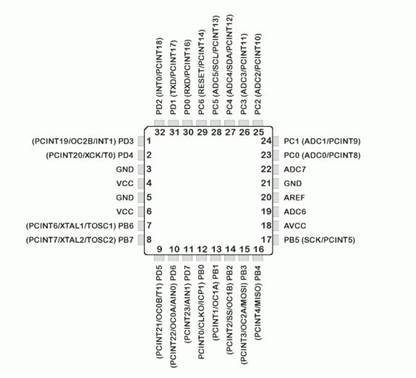
Estos tendrán que conectarse a los mismos pines en la PCB que se desea programar. Para lo cual hay que revisar el datasheet y ver cuales pines corresponden para conectarlos entre sí. Revisar Arduino as ISP and Arduino Bootloaders
DTR=Reset
AtMega voltaje, entre 3 y 5.5
Connect the arduino to the board to program it. You have to check which pins of the Arduino programmer you have to connect, which are:
RESET 10
PIN_MOSI 11
PIN_MISO 12
PIN_SCK 13
VCC
GND
These will have to connect to the same pins on the PCB that you want to program. For which it is necessary to review the datasheet and see which pins correspond to connect them to each other. Review Arduino as ISP and Arduino Bootloaders
DTR = Reset
AtMega voltage, between 3 and 5.5
El siguiente paso una vez todo conectado entre el Arduino y el Fabduino es hacer un bootloader del mismo código que se subió al Arduino. Al hacer esto, me daba error. Revisé la placa y encontré que había unas partes mal soldadas y las arreglé. Pero otro error persistió y no he podido resolverlo.
The next step once everything is connected between the Arduino and the Fabduino is to make a bootloader of the same code that was uploaded to the Arduino. When I did this, I got an error. I checked the PCB and found that there were some poorly welded parts and I fixed them. But another error persisted and I have not been able to solve it.
avrdude: Expected signature for ATmega328P is 1E 95 0F
Double check chip, or use -F to override this check.
Error quemando bootloader
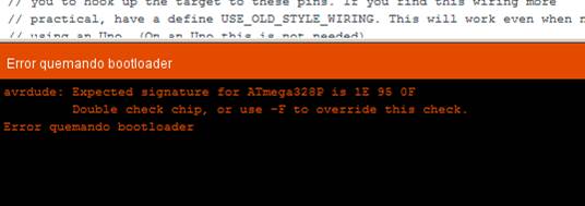
La solución fue que cada vez que aparecía ese mensaje es que la computadora había dejado de detectar el Arduino chino, así que debía instalar de nuevo el driver cada vez.
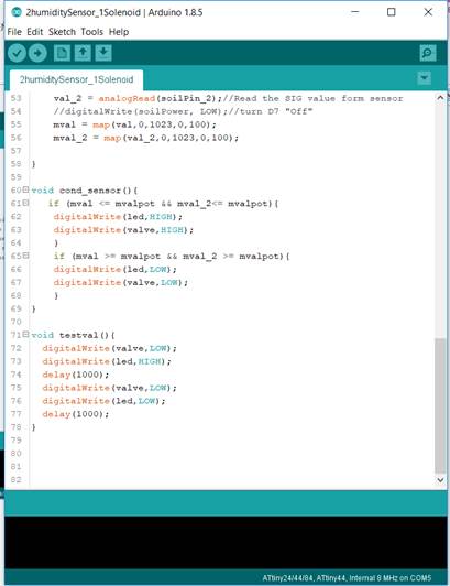
Ya superado este problema, escribí mi código de Arduino basándome en los códigos que había escrito en tareas anteriores. Por ahora solo logré leer los dos sensores de humedad, sacar un medio ente ellos con un rango de 0 a 100% de humedad. Estos, dependiendo del tope que colocará como el margen para abrir el solenoide el cual se controlaba con un potenciómetro el cual hacía variar ese tope y así poder calibrar el sistema. Por ejemplo, si veía que la tierra estaba muy seca, con el potenciómetro podía bajar el mínimo de humedad para que se accionara el sistema y mojará la tierra para las plantas. También dependiendo de ese rango se prende un led ubicado en la placa como aviso complementario.
The solution was that every time that message appeared, the computer had stopped detecting the Chinese Arduino, so I had to install the driver again every time.
Having overcome this problem, I wrote my Arduino code based on the codes I had written in previous tasks. For now I only managed to read the two humidity sensors, take out a medium between them with a range of 0 to 100% humidity. Depending on the top porcentage that will be placed as margin to open or close the solenoid. This margin is set with a potentiometer which varied the parameter calibrate the system almost manually. For example, if you saw that the earth was very dry, with the potentiometer you could lower the minimum humidity to trigger the system and wet the soil for the plants. Also depending on this range, a led on the board is lit as a complementary warning.
Este es el código / This is the code
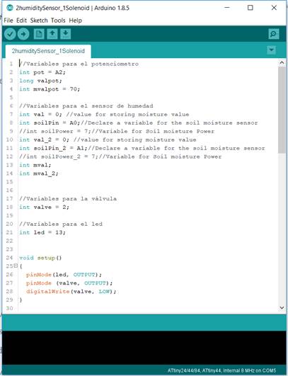
//Variables para el potenciometro
int pot = A2;
long valpot;
int mvalpot = 70;
//Variables para el sensor de humedad
int val = 0; //value for storing moisture value
int soilPin = A0;//Declare a variable for the soil moisture sensor
//int soilPower = 7;//Variable for Soil moisture Power
int val_2 = 0; //value for storing moisture value
int soilPin_2 = A1;//Declare a variable for the soil moisture sensor
//int soilPower_2 = 7;//Variable for Soil moisture Power
int mval;
int mval_2;
//Variables para la válvula
int valve = 2;
//Variables para el led
int led = 13;
void setup()
{
pinMode(led, OUTPUT);
pinMode (valve, OUTPUT);
digitalWrite(valve, LOW);
}
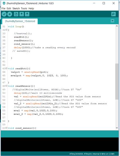
void loop()
{
//testval();
readPot();
readSensor();
cond_sensor();
delay(1000);//take a reading every second
// saveSD();
}
void readPot(){
valpot = analogRead(pot);
mvalpot = map(valpot,0, 1023, 0, 100);
}
void readSensor(){
//digitalWrite(soilPower, HIGH);//turn D7 "On"
delay(10);//wait 10 milliseconds
val = analogRead(soilPin);//Read the SIG value form sensor
//digitalWrite(soilPower, LOW);//turn D7 "Off"
val_2 = analogRead(soilPin_2);//Read the SIG value form sensor
//digitalWrite(soilPower, LOW);//turn D7 "Off"
mval = map(val,0,1023,0,100);
mval_2 = map(val_2,0,1023,0,100);
}
void cond_sensor(){
if (mval <= mvalpot && mval_2<= mvalpot){
digitalWrite(led,HIGH);
digitalWrite(valve,HIGH);
}
if (mval >= mvalpot && mval_2 >= mvalpot){
digitalWrite(led,LOW);
digitalWrite(valve,LOW);
}
}
void testval(){
digitalWrite(valve,LOW);
digitalWrite(led,HIGH);
delay(1000);
digitalWrite(valve,LOW);
digitalWrite(led,LOW);
delay(1000);
}
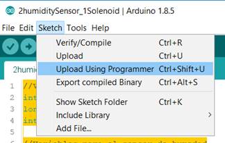
El programa se subía al FabDuino a través del Arduino Uno, para eso había que usar la función en Programa / Subir usando programador. Si se hacía de la manera tradicional presionando solo subir, el código se grabaría en el Arduino uno que funge como programador y no en el Fabduino que es controlador que usaremos.
The program was uploaded to the FabDuino through the Arduino Uno, for that it was necessary to use the function in Program / Upload using programmer. If it was done in the traditional way by pressing only upload, the code would be recorded on the Arduino UNO that works as programmer and not on the Fabduino that is the controller that we will use.
Hidráulica / Hydraulics
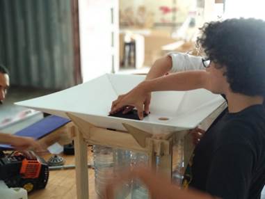
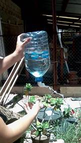
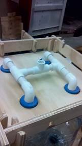
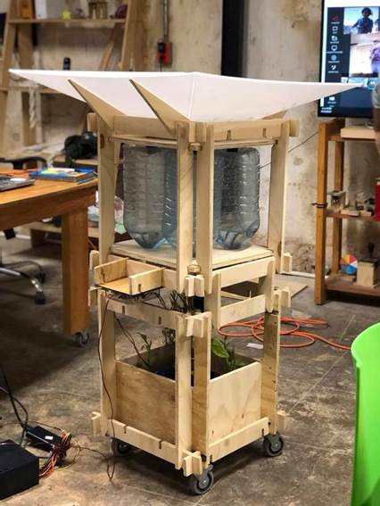
El sistema consiste en un cono de recolección de agua que la deposita en 4 botellas de agua recicladas de 5lts cada una. Estas botellas se interconectan para que el solenoide deje salir el agua, pero a la vez para que el agua se nivele (vasos comunicantes) entre ellas si alguna se llena más que la otra. El agua liberada riega las plantas a través de un aspersor
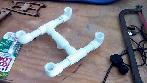
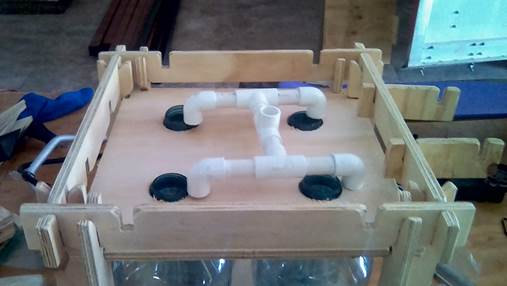
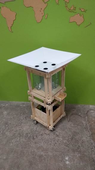
Desde arriba hacia abajo. Se diseñó y cortó en laser una pirámide invertida y truncada en plástico la cual recolectaba el agua de lluvia. Su base tiene 4 aberturas donde se colocaron 4 embudos impresos en 3d que direccionan el agua a las aberturas dentro de los recipientes. Los recipientes se les adaptó tubería de pvc de ½” y a través de codos y t´s se logró comunicarlos entre si y con la válvula. Por último se conectó la válvula y el aspersor
El válvula Solenoide es de sparkfun, de 12 Vy su función es abrir y cerrar la válvula interna que tiene. Se conecta a tierra y corriente. El controlador lo que hace es a través de la corriente que pasa, abrir o cerrar, cuando deja de recibir corriente se cierra automáticamente
The system consists of a water collection cone that deposits it in 4 recycled water bottles of 5 liters each. These bottles are interconnected so that the solenoid lets the water out, but at the same time so that the water levels up (communicating vessels) between them if one is filled more than the other. The released water irrigates the plants through a sprinkler.
From top to bottom. An inverted and truncated plastic pyramid was designed and cut in laser, which collected the rainwater. Its base has 4 openings where 4 funnels printed in 3D were placed that direct the water to the openings inside the containers. The containers were adapted with ½ "pvc pipe and through elbows and t's they were able to communicate with each other and with the valve. Finally the valve and the sprinkler were connected
The solenoid valve is sparkfun, 12 V and its function is to open and close the internal valve that it has. It is connected to ground and current. The controller what it does is through the current that passes, open or close, when it stops receiving current it closes automatically
The Result
Final Video
Presentation slide / Dispositiva de presentación
Link to poster 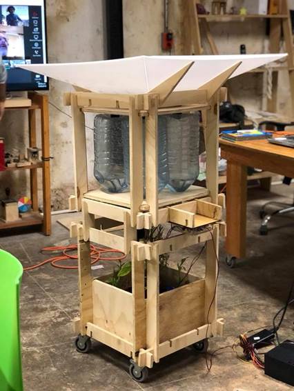
Download files / Descargar archivos