Week 5 / semana
5
Electronics Production
characterize the specifications of your PCB production process
make an in-circuit programmer by milling the PCB
Introduction
We will learn the how make a PCB. But not any PCB, a very important one, that will be usefull in the future. We will cut the copper board with the miling machine, then solder all the components to finally program the board.
group assignment:
characterize the specifications of your PCB production process
I missundestood this part of the assignment. I though that the first part of the production of the pcb was in a group to undestand the process and then the soldering and programming individually.
Now I undestand we need to test the machine and the possibilities and limitations of it. Like we did with the laser cutter machine.
1. On the fab academy page
http://academy.cba.mit.edu/classes/electronics_production/index.html
Open this links in blue on another window.
2. Traces is the png file for to trace the board
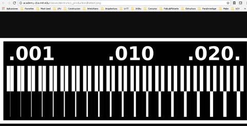
http://academy.cba.mit.edu/classes/electronics_production/linetest.png
Download the file
3. Interior is for the outline of the PCB, is the one that cuts the shape
http://academy.cba.mit.edu/classes/electronics_production/linetest.interior.png
Download the file
4. 1/64” is the aproximation of the result I am going to get with that diameter of mill
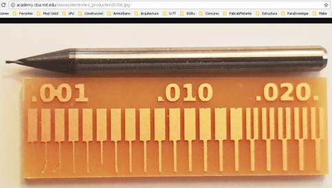
http://academy.cba.mit.edu/classes/electronics_production/0156.jpg
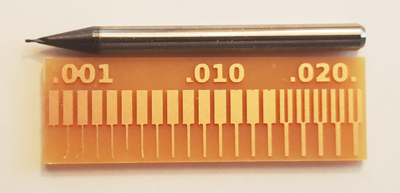
5. 0.0010” is the aproximation of the result I am going to get with that diameter of mill
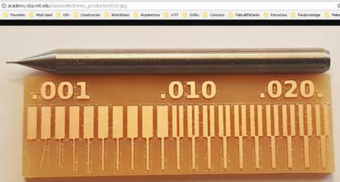
http://academy.cba.mit.edu/classes/electronics_production/010.jpg
6.
With
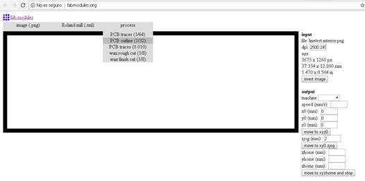
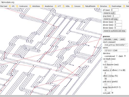
modules we will generate the G code wich is a .rml
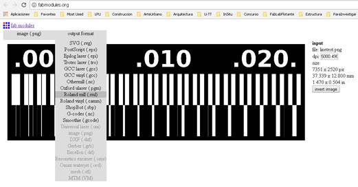
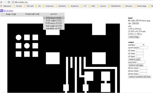
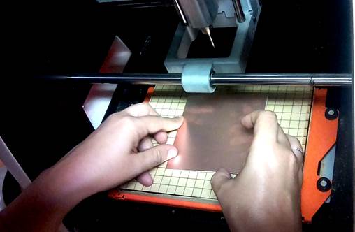
open Fab Modules
http://fabmodules.org/
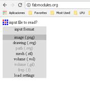
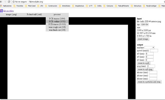
7.
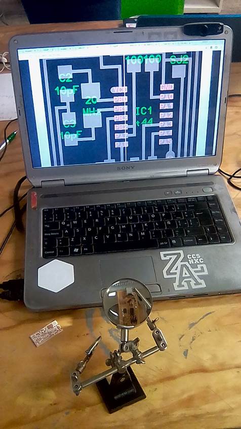
In
Input format select image PNG
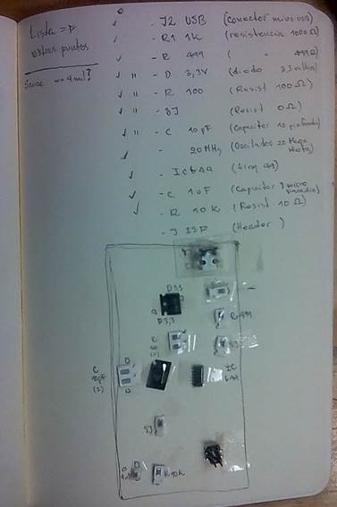
In the browser I selected the png I downloaded before, named linetest.png
8. On output I selected Roland Milling (.rml)
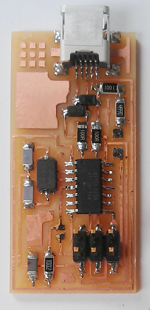
9. On Process / for the traces png file / 1/64
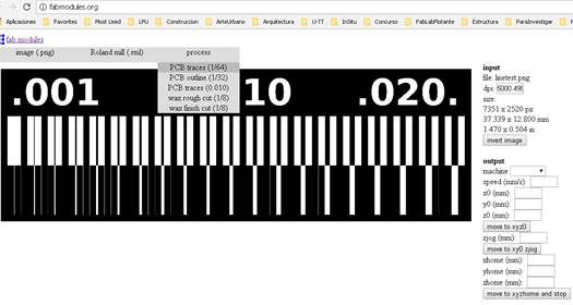
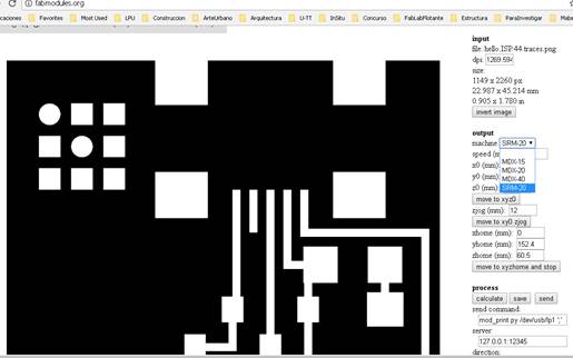
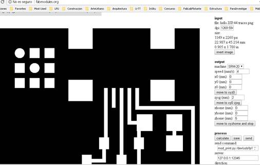
10. Output selected srm-20
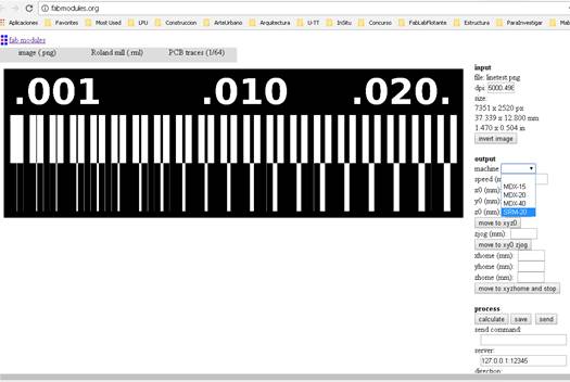
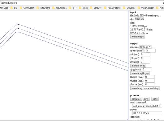
11.
The
values x, y, z on 0
xhome
(mm):
yhome (mm):
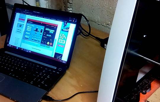
zhome (mm):
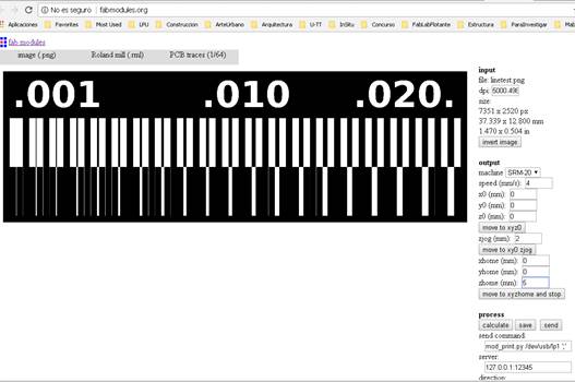
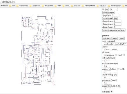
12. Press calculate and wait
13. I saved the file
14. I did the whole process again with the linetest.interior.png file, but with a little different configuration in the millin. It is 1/32
15. Orbit and I checked the drawing has 3 layers or lines

16. I Saved the files on a USB. And open them with the program in the computer with the specific software to control the machine
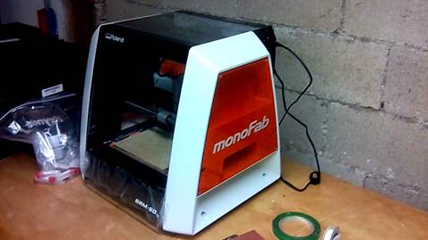
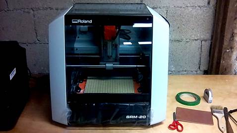
17. The machine we have in the Fab Lab is a Roland Monofab SRM-20
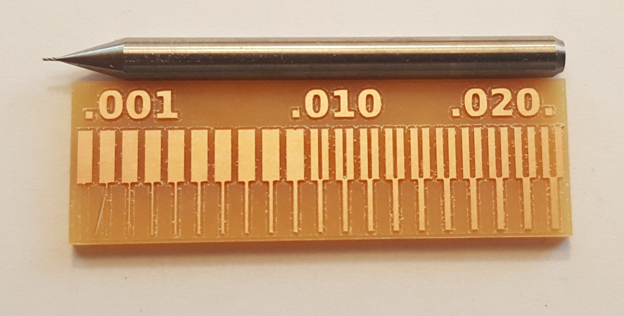
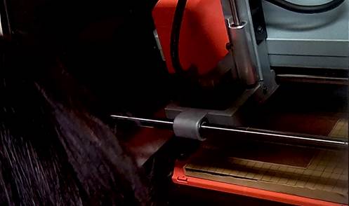
18. We cut the tests with two different mills
19.
1/32”
above
1/64” below
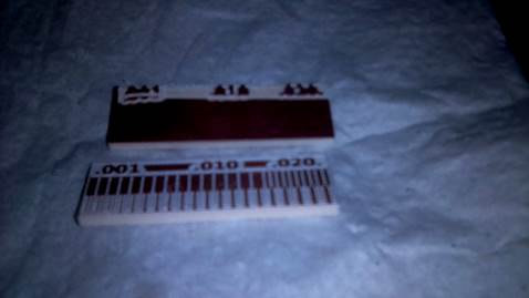
20. The thicker mill has much less resolution but it is stronger when cutting the PCB
individual assignment:
make an in-circuit programmer by milling the PCB
1. the goal is to make a PCB by ourselves
2.
Download
the two png´s. Traces and Interior
http://academy.cba.mit.edu/classes/embedded_programming/hello.ISP.44.traces.png
http://academy.cba.mit.edu/classes/embedded_programming/hello.ISP.44.interior.png
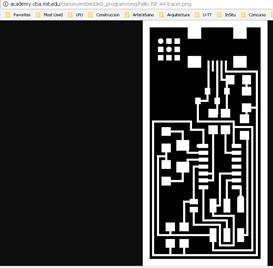
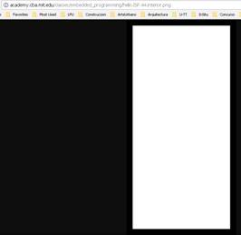
Trace / Interior
3.
With
modules we will generate the G code wich is a .rml
open Fab Modules
http://fabmodules.org/
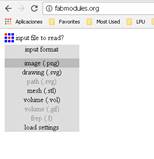
4.
In
Input format select image PNG
In the browser I selected the png I downloaded before, named traces
5. On output I selected Roland Milling (.rml)
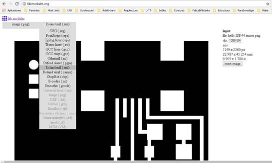
6. On Process / for the traces png file / 1/64
7. Output selected srm-20
8.
The
values x, y, z on 0
xhome
(mm):
yhome (mm):
zhome (mm):
9. Press calculate and wait
10.
Right
click for orbit
Wheel click for pan
11.
I
saved the file
I was in the dowload folder. There is no message that it is saving, so just go
straight to the folder and it will be there
12. I did the whole process again with the Interior pgn file, but with a little different configuration in the millin. It is 1/32
13. Orbit and I checked the drawing has 3 layers or lines
14.
I
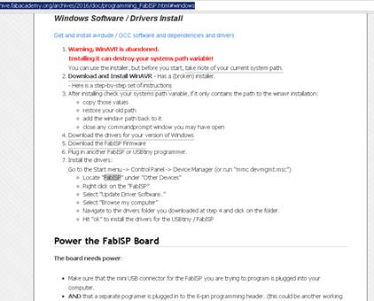
downloaded the drivers
first I clicked on programming on the fab academy class
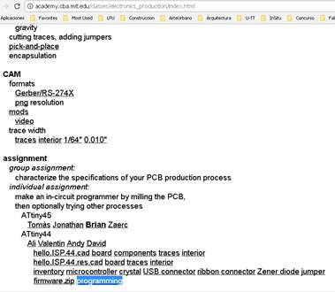
15. This window opened
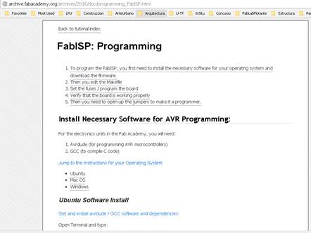
16. For windows
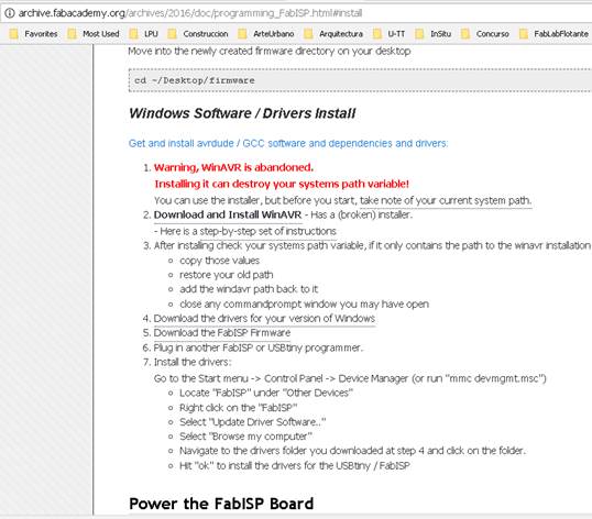
17. I didn´t care about the warning and continued with the next step
18.
I
looked a couple of tutorials recommended
http://fab.cba.mit.edu/classes/863.16/doc/projects/ftsmin/windows_avr.html
http://fab.cba.mit.edu/classes/863.16/doc/projects/ftsmin/index.html#toolchain
19.
Donwloaded
the WINAVR
https://sourceforge.net/projects/winavr/files/
20.
download
the drivers for your version of Windows (Ada fruit)
https://learn.adafruit.com/usbtinyisp/drivers
21. download the FabISP Firmware
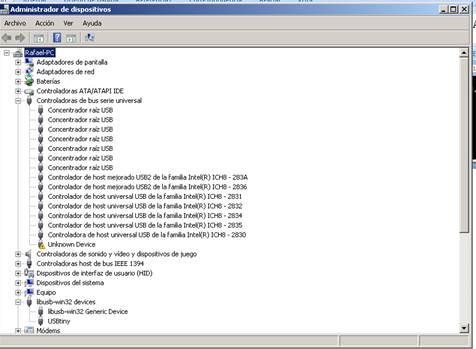
22. after installing ada fruit, I went to Control Panel/ device Manager
23. Locate "FabISP"
24. Right click on the "FabISP"
25. Select "Update Driver Software.." This can take a couple of minutes till the option to update is available
26. Select "Browse my computer"
27. Navigate to the drivers folder you downloaded the firmware. I put it it in the Desktop
28. Hit "ok" to install the drivers for the USBtiny / FabISP
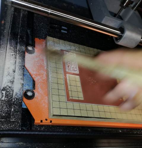
29. The bed on the monofab must be flat, so Jesus, one of the worers of the FabLab was carving the pdf bed with the machine
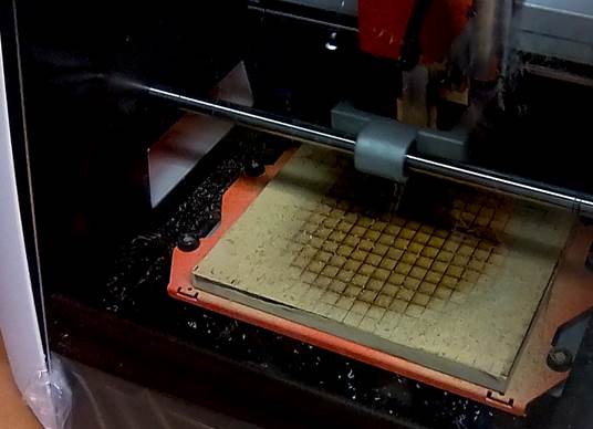
30. I took the two .rml files in an usb and loaded them to the machine that controls the Monofab
31. We put double side tape on the back on the virgin PCB and place it inside the machine
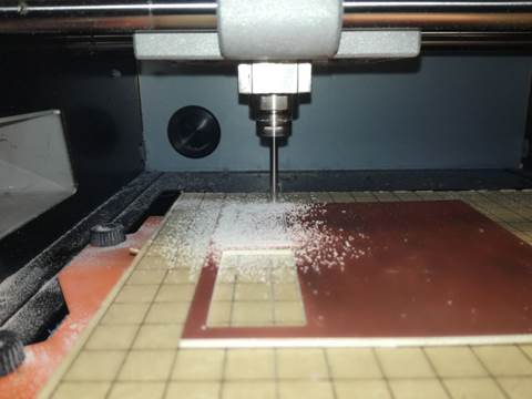
32. Set the o,o,o point in the machine and start milling
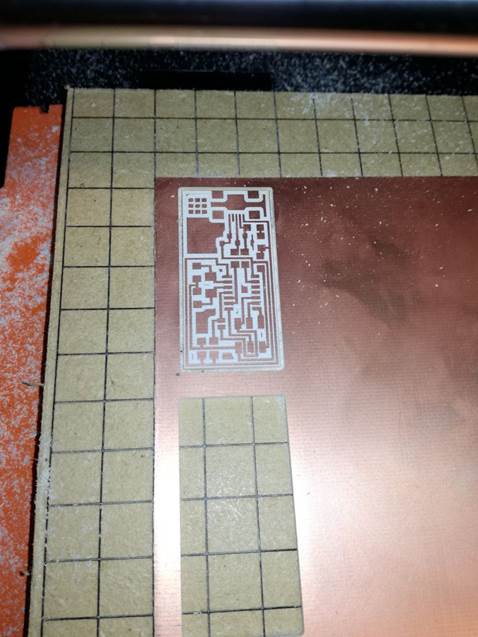
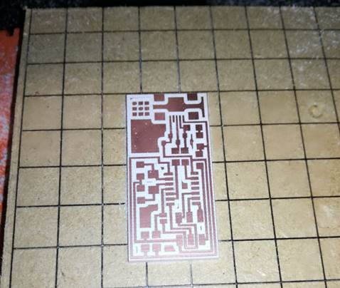
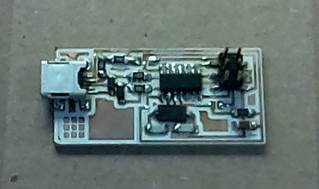
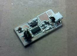
33. The result
34. I identify the components if the PCB in other to search them in the lab
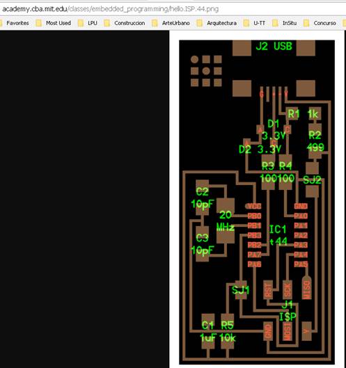
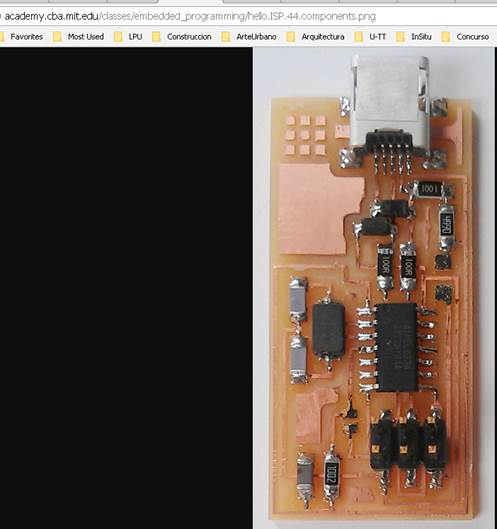
http://academy.cba.mit.edu/classes/embedded_programming/hello.ISP.44.png
http://academy.cba.mit.edu/classes/embedded_programming/hello.ISP.44.components.png
35. I compare the image with an exisitin pcb
36. I collected all the components and fix them to my note book with tape aproximately where they should be on a scaled board I drawed. Also made a list of the components with the meaning of the shortcuts
37. I cleaned my board with soap and a sponge
38. Then started soldering the components to the board. First the small one, then the big ones. Having the two images of the board always near to check the location of each component I was soldering
39. I saw some tutorials about soldering
https://www.youtube.com/watch?v=Qps9woUGkvI
but Jesus from the Fab Lab, showed me to solder putting a a little of soldering
paste on the board, the place the component, put a drop of tin in the countin
and put it into the joint you want to solder
40.
The
next step is to programm the board
I am following this tutorial
http://archive.fabacademy.org/archives/2016/doc/programming_FabISP.html#windows
41.
I did
till step 7 yesterday
but now…
42. I can not make fuse, because the USBtiny is been recognized
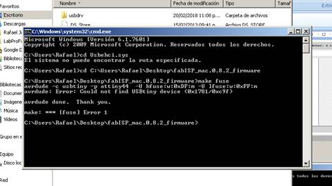
43. I tried several tutorials ans options and any worked
44. I can´t programm the board L
45. I think my board has an error in the conections. I have to check it with the multimeter
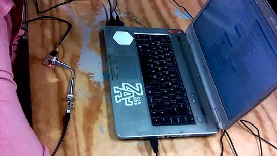
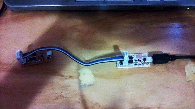
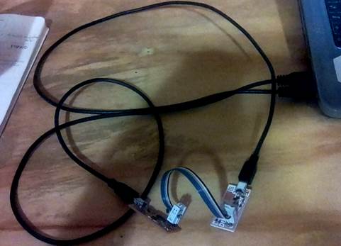
46. After talking with my tutor. The problem was that I wasn´t giving power to the programmer ISP, as you can see in the picture. Both FabISP´s need to be connected trough USB cable to the computer to also give power to both, and the ribbon cable is just for communication between them
47.
I
am trying again. Back to the tutorial
http://archive.fabacademy.org/archives/2016/doc/programming_FabISP.html#install
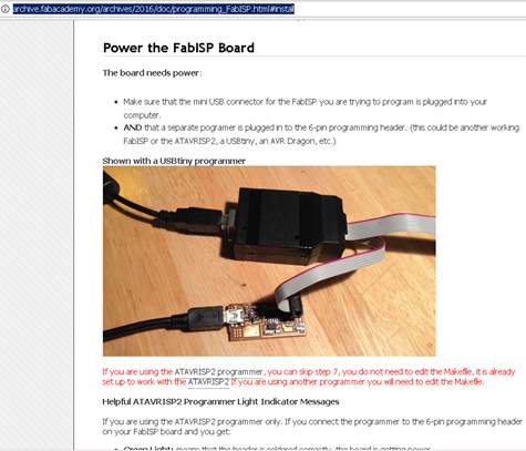
48. Make sure that the mini USB connector for the FabISP you are trying to program is plugged into your computer
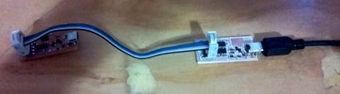
49. I connected the programmer with the one that is going to be programmed by a cluster of jumpers, beeing carefull that ground is connected with ground with the same cable. Normally the black
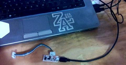
50. Make sure as well that the FabISP programmer, (the programmer has the o k resistance removed) is also connected by USB cable to the computer
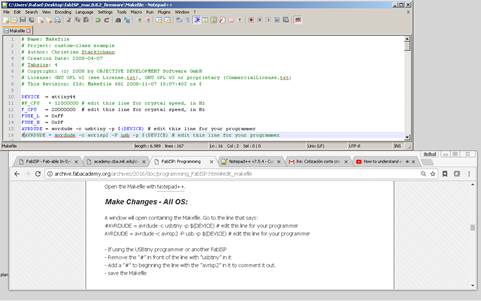
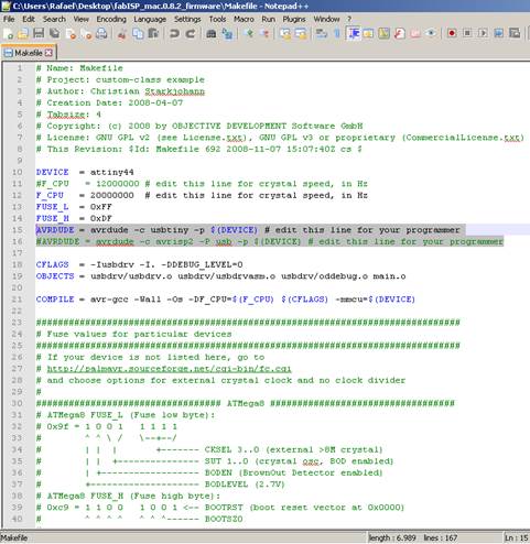
51. Edit the Makefile. It is in the firmware folder that I downloaded in the desktop. Open it with Notepad++ that I downloaded previosly
52. A window will open containing the Makefile. Go to the line that says:
#AVRDUDE = avrdude -c usbtiny -p $(DEVICE) # edit this line for your programmer
AVRDUDE = avrdude -c avrisp2 -P usb -p $(DEVICE) # edit this line for your programmer
If using the USBtiny programmer or another FabISP
Remove the "#" in front of the line with "usbtiny" in it
Add a "#" to beginning the line with the "avrisp2" in it to comment it out.
save the Makefile
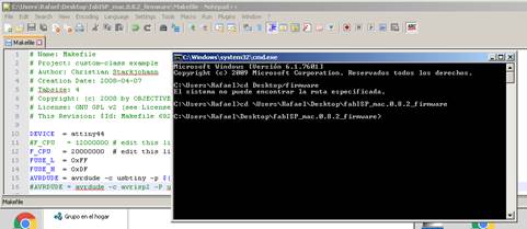
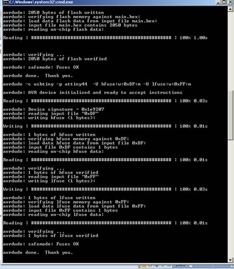
53. Open your terminal / command line interface and move to the firmware directory.
54.
The
secuence of commands
make clean
make hex
make fuse
make program
55. Wooo! Success!
56. Both devices appear in the list
Hero Shots
Conclusions
· We built a Fab ISP, “is an in-system programmer for AVR microcontrollers, designed for production within a FabLab. That is, it allows you to program the microcontrollers on other boards you make, using nothing but a USB cable and 6-pin IDC to 6-pin IDC cable. It's based on the USBtiny and V-USB firmwares, which allow the ATtiny44 to perform USB communication in software. Programming can be done through avrdude.”. This board will be useful in the future to program other boards.
· One board is the programmer (the one we took the 0k resisitance) and the other is programmed by the first one. Later, when we use our board as programmer, we will need to remove the 0k resisitance
·
The
FabISP always need to be connected to the USB cable is order to work, because
is not only about the command to burn that goes trough it, also the power that
feed the microcontroller.
Download file