Week 8 / Semana 8
Index
test runout, alignment, speeds, feeds, and toolpaths for your machine
Introduction
I will design and fabricate something big enough to be done in the CNC router and be able to check joints, tolerances, etc. As other assignments here I created the basic structure of my project that will evolve in the process.
Software
· Vcarve
· Rhinoceros
Hardware
· CNC router
· Drill
Materials
· Plywood
· Sand paper
group assignment
test runout, alignment, speeds, feeds, and toolpaths for your machine
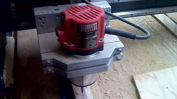
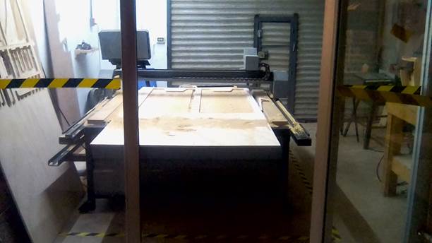
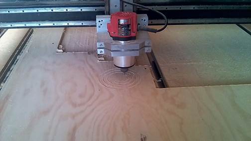
The machine

The cnc router is a Somey machine. It is a local brand from this city (Mérida, Yucatán)
Cutting surface: 1, 45 x 1, 75 m
Router: Milwaukee
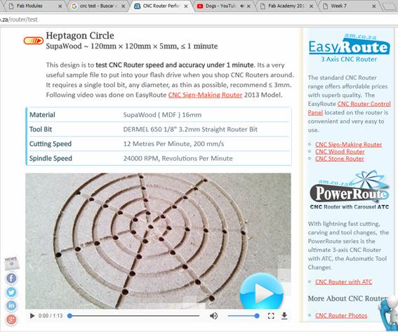
The test
1.
We
downloaded a test file we found on the internet.
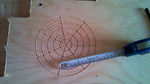
CNC Router Performance Test
2. Downloaded also de DXF file, from that web page
3. Previously we installed the vcarve software
4. Opened the dxb on the program
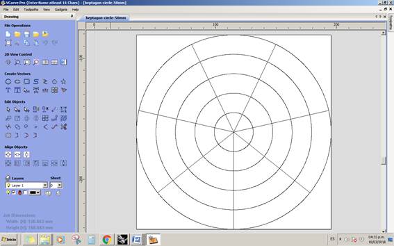
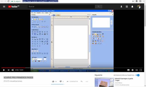
5. We watched another tutorial to use the machine. VCARVE PRO PRIMEROS PASOS
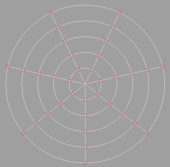
6.
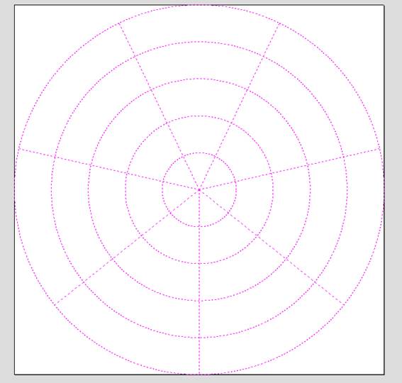
Selected
the lines of the drawing that are going to be engraved (in this case, all of
them)
the lines become dot lines
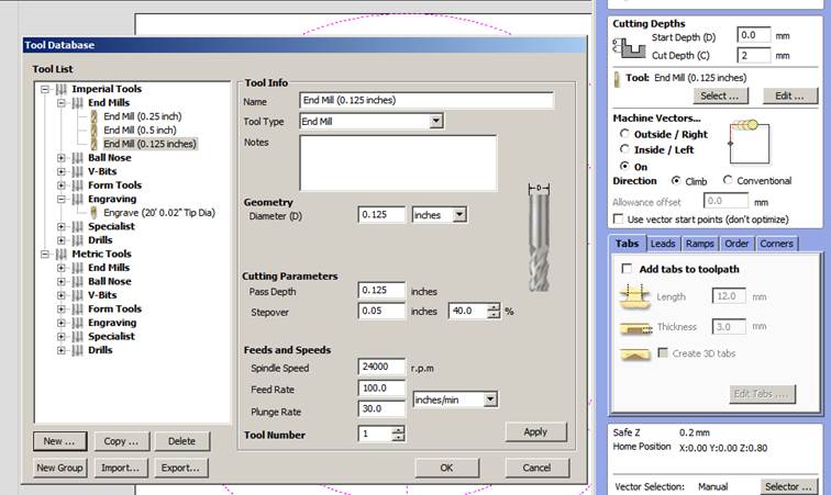
7. Select or create your router bit
8. We gave a name to the file
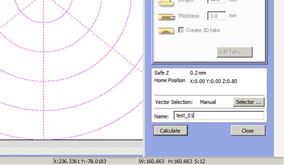
9. I realized that the drills didn´t appear. Vcarve do not recognize the dots or points. I want back to Rhino and draw circles the size of the drill I am going to use. In this case 1/8 “. I exported the file to dxf.
10. I opened the file on Ilustrator to safe it again in DXF. Normally, the files exported straight from Rhino don´t work on vcarve, so I have to process the file in Ilustrator after Rhino.
11. Did all the steps again till step 10.
12. Selected the lines that need to engrave. Chose drill, depth and pressed calculate
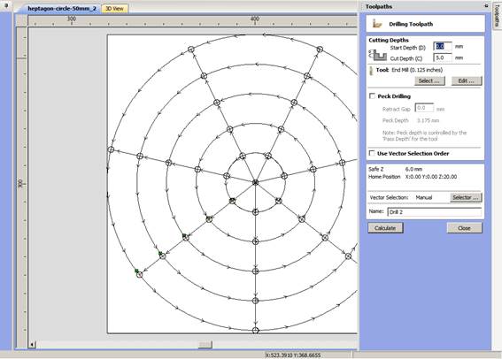
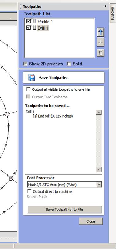
13. After calculating I saved
the gcode on my folder with “save toolpath to file”
Port Processor Mach2/3 ATC Arcs (mm) (*.txt)
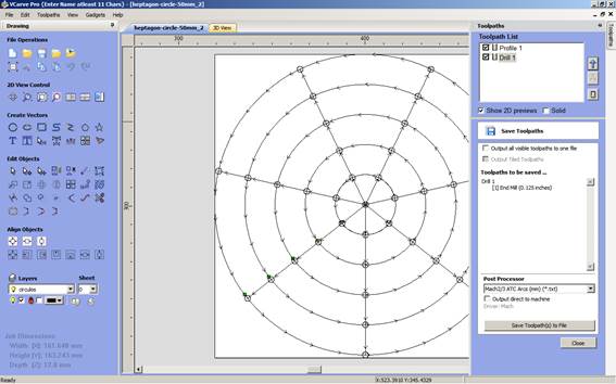
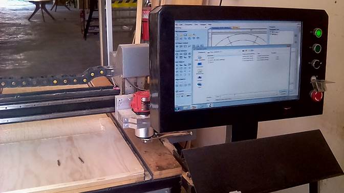
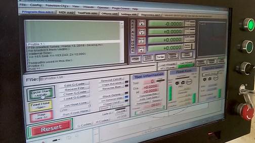
14. Bring it to the machine and import it to the CNC software
15. Changed the drill to the 1/8” bit
16. Move the spindle to my 0,0,0. That means the bottom left of the drawing where the machine is going to cut.
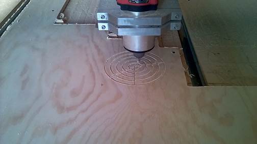
17. Pressed “start Cycle”
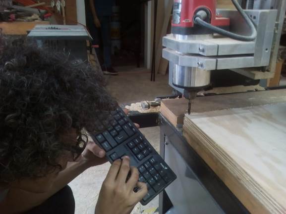
18. Be close to the controls of the machine. In case something goes wrong press the red button to stop the machine
19. If the machine is been forced while cutting, you mak it slower in the feed rate. For 12mm triplay wood we put normally 70%
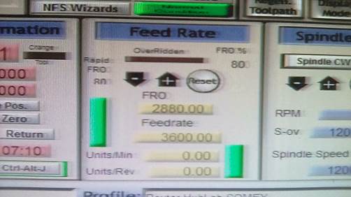
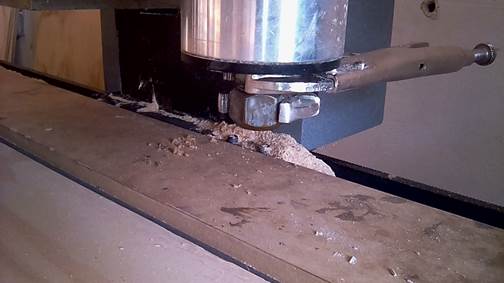
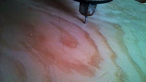
20. The test was successful. The machine cut exactly like the model
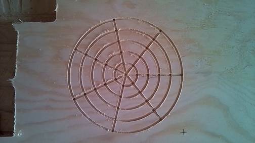
21. The video while cutting
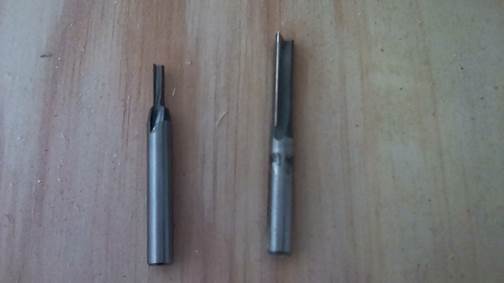
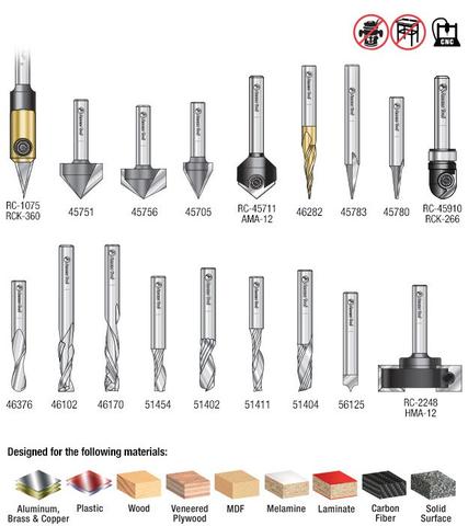
Different bits for cnc router. Each one has a type of cut or carv for specific materials
individual assignment
make something big
1.
I
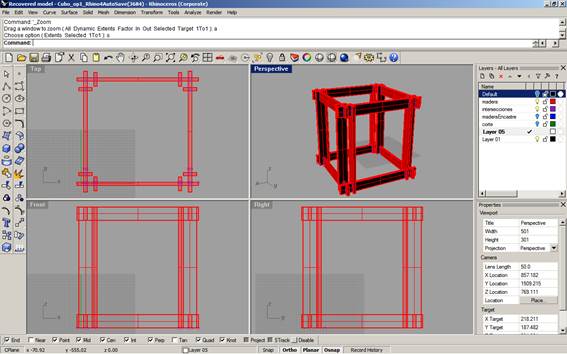
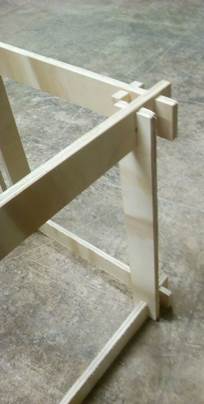
designed one piece of my final project. It consists on a box that will be
filled in the future with water containers, container to grow things or water
collectors. I love cubes, I think they are very easy forms that make modules
and you can stack or joint them creating new forms. My idea is to build
something tridimensional with 2d shapes. Small pieces that together create
something big.
I used rhinoceros
The idea is to cut small pieces of wood, that been assembled generate a
structural cube that can be stacked
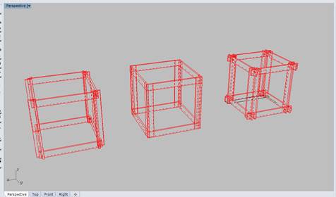
2. I started designing 3 different types with different types of joints.
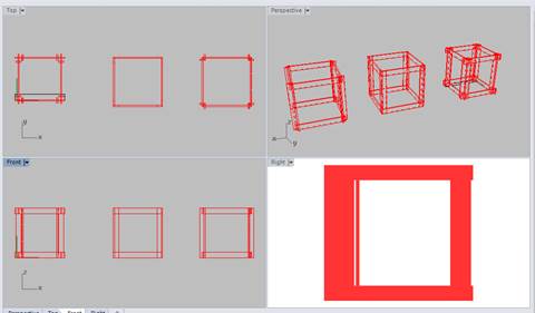
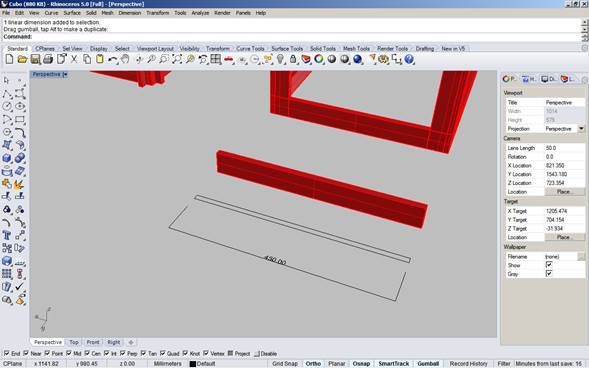
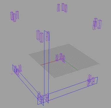
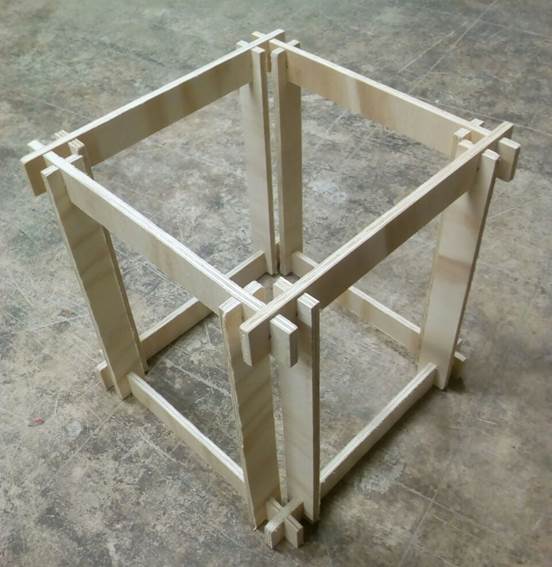
22. I draw the cube starting by one side, that’s going to be the same size for all the sides. Y already knew I was going to use 12mm wide wood. So I drew a rectangle of 450mm x 12mm. That rectangle was extrude by 50mm. And then copy and rotated to create the cube
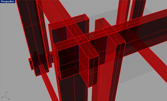
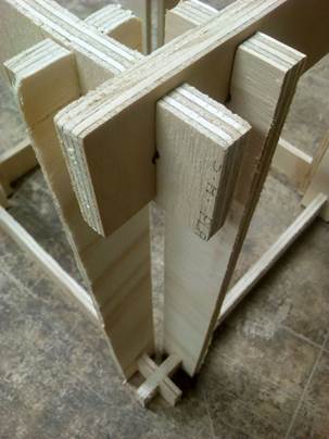
23. For the cube I selected Y just separate the different press fit joints instead of concentrating them on the same node.
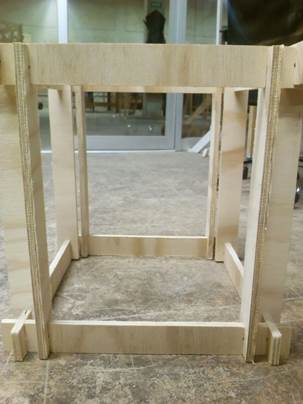
3. The joint between them are easy, just single press fit. I think in the process this piece can become cleaner with the joints. But so far I like it, because the box can be carried by parts and assembled Insitu
4.
With
the intersect command I identified where the pieces intersect
I draw by connecting lines the shape of the wood with the press-fit
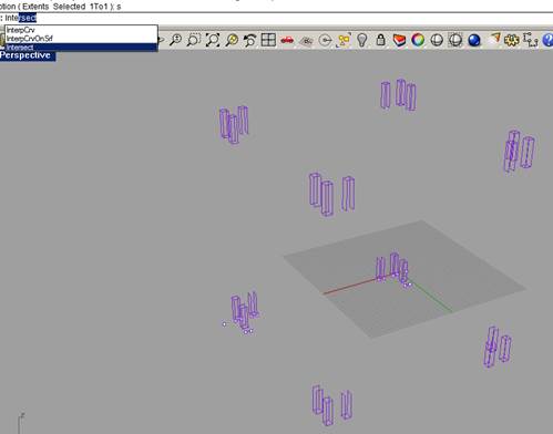
converted them into surfaces
Unrolled the pieces to have them flat on cplane
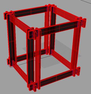
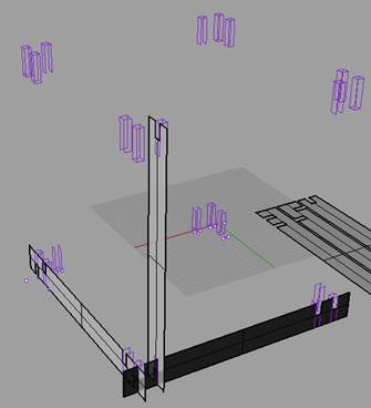
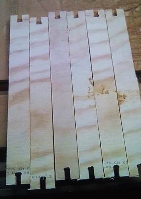
5. I know that each of the two types of the horizontal stripes was going to be repeated 4 times in the box. For the vertical stripes I needed 4 pieces per box, and they are all the same
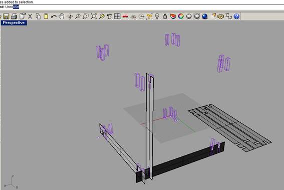
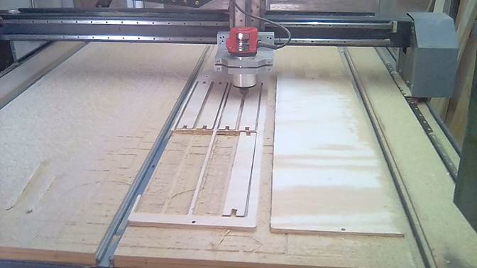
6. I used 12mm thick plywood. I measured the pieces of wood where I was going to cut the stripes. I draw the pieces on rhino and place the stripes in it
7. Export it into .dxf. (cad 2000)
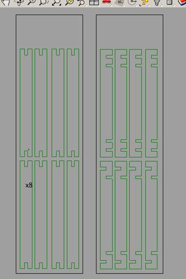
8. Open vcarve
9. Drag the file into the program
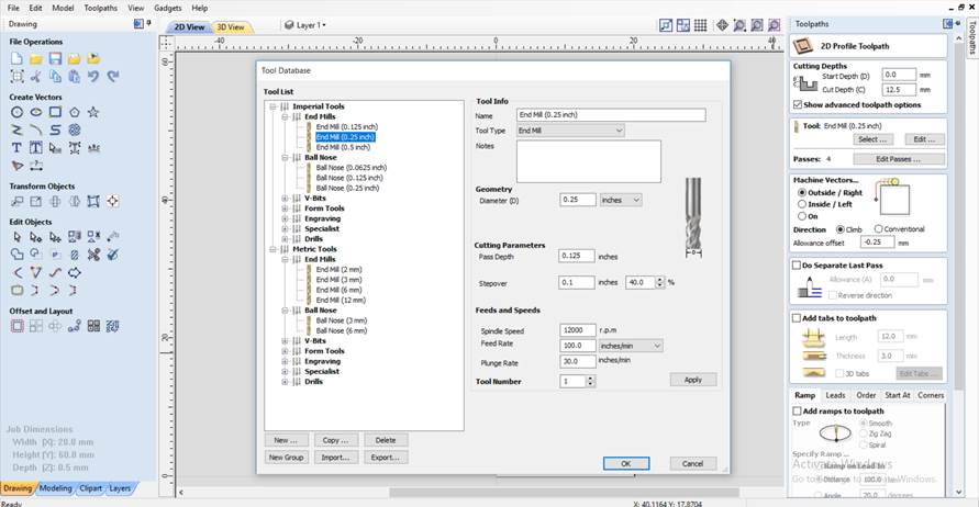
10. Set the parameters to cut the file.
a. I set cut depth to 12.5mm. The plywood is 12mm but it´s not perfectly flat, so I added 0.5mm.
b. For tool I used a Ø 0.635mm (Ø 0.25”) End Mill.
c. I set the pass Depth to 0.125” (3mm), which means the CNC is going to do 4 passes to cut through the plywood.
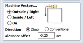
d. I set the Vectors to be cut by the machines from the Outside and the direction to the Right.
11. Every machine has its tolerances. For this machine is recommended to have an allowance offset of -0,05. But mostly always have to check the real width of the material that is very usual that is not uniform. In this case I used a -0.25mm allowance offset.
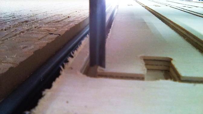
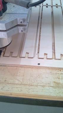
12. I made the tbones for the corner, that way the pieces can fit together, because otherwise the drill will not mill a 90° corner.
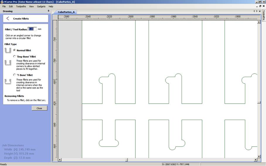
13. The button to make the tbones
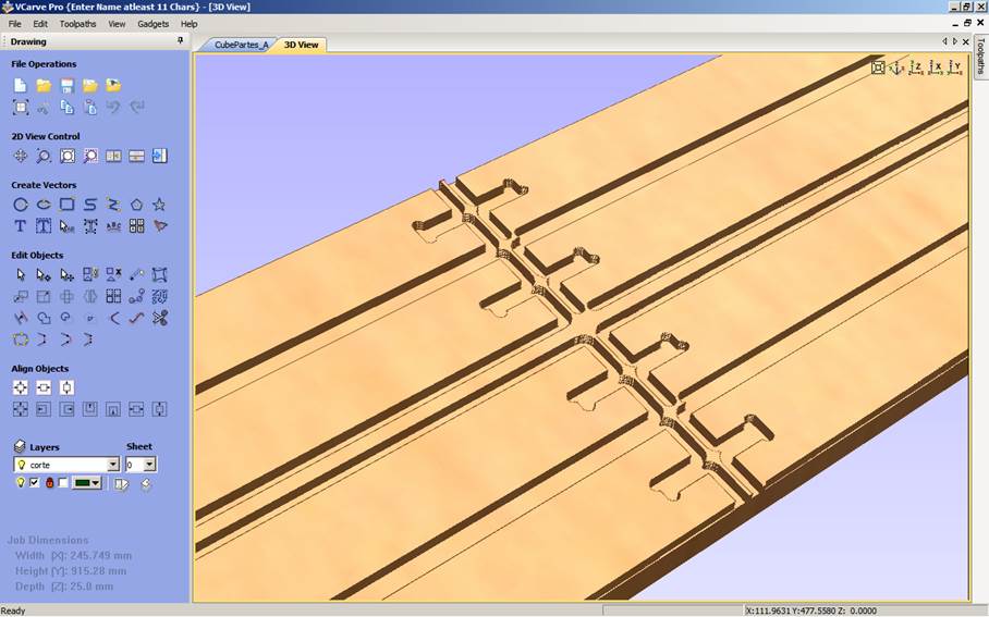
14. Simulate the cut
15. Export the file into a gcode
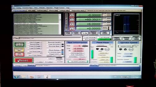
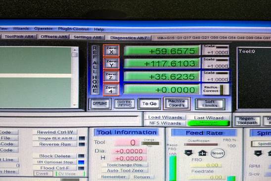
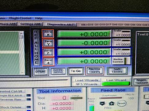
16. I had to set the machine to Zero (0,0,0).
a. First, I moved the tool to the position in x,y,z where it start (or where its zero should be)
b. Then I set x,y,z to 0 in the control interface of the machines.
17. Now I can send the gcode following the steps I put down in the previous task
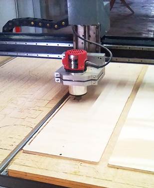
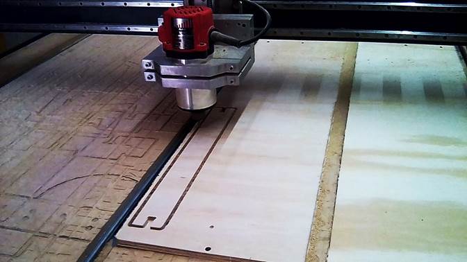
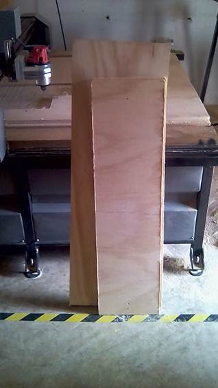
18. The result
Conclusions
1. It is recommended for the press fit, to put angles where the other piece is going to fit, that makes the assembly easier. I didn´t do it in this assignment, but I will do it in the future.
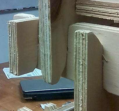
2. I recommend cutting two pieces first and check how they fit together. If they are not fitting well, then make adjustments, instead of cutting everything and finding out at the end that the tolerances are wrong.
3. Make bridges, which mean that the pieces will not be cut completed; a little bridge is going to be left to keep the piece in its place as possible while cutting.